Simulink Model for Doorbell and Heater.
Aim: To make a Simulink model of doorbell using Solenoid.
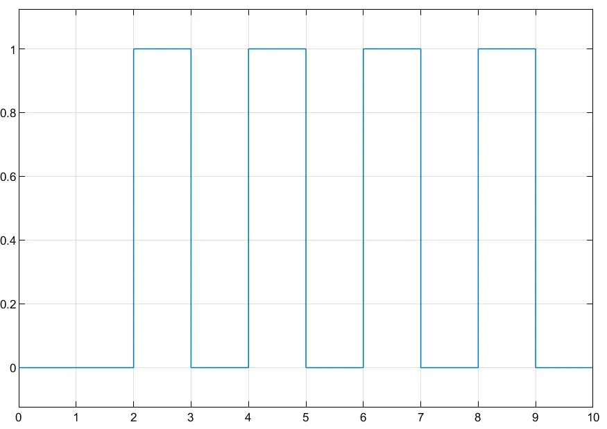
Objective: To Create a situation where the switch is closed for 2 seconds and then released and to observe the physical movement of the plunger.
Introduction:
A doorbell uses the magnetic field created by the electromagnet to move a metal arm to strike the bell and this produces sound.
In a doorbell, the electromagnet operates a self-interrupting circuit. When the switch is closed, the circuit closes and the electromagnet moves the metal arm. When the metal arm moves, it interrupts the circuit and the electromagnet stops. When it stops, the metal arm falls back into position, completing the circuit and starting the process over again.
This cycle repeats quickly over and over again as long as the switch is closed.
Model:
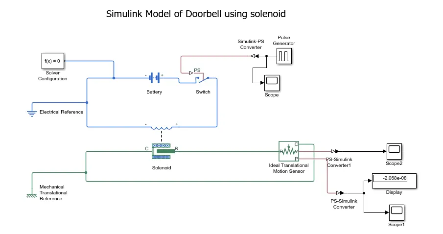
Link to the model: https://drive.google.com/file/d/1AGiO65TvojqP3rn-oPNqdDk9rQO-K9f_/view?usp=sharing
Explanation:
A pulse generator is used to provide the required input to the circuit. A Pulse Generator block generates square wave pulses at regular intervals.
A Simulink-PS converter is used to convert the Simulink signal from the pulse generator to Physical signals. A scope is used to display the signals generated.
A 12V battery is connected to the solenoid through a switch. The Solver Configuration block specifies the solver parameters that your model needs before you can begin simulation. The circuit is grounded using an electrical reference.
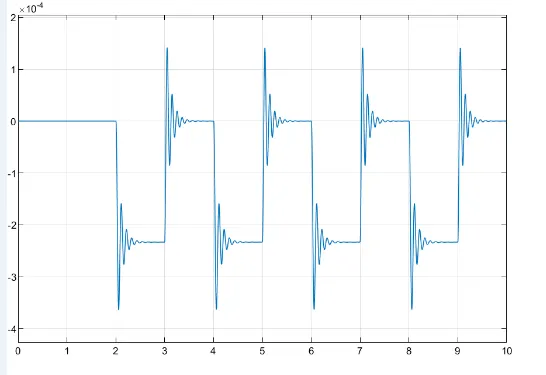
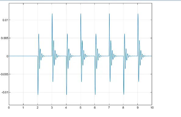
The plunger of the solenoid activates the translator motion sensor. Connections R and C are mechanical translational conserving ports that connect the block to the nodes whose motion is being monitored. Connections V and P are physical signal output ports for velocity and position, respectively. The solenoid and the Ideal sensor are given a reference point. The controlled signal(output) is converted into an simulink signal using PS-Simulink Convereter displayed using the display block.
Results:
Pulse Generated
Scope1
Scope2
Conclusion:
When the switch is closed for 2 seconds using a pulse generator, solenoid receives power and the plunger moves from a position R to position C against the spring and the metal arm hits the bell, producing sound.
Heater Simulation:
Aim: To use a thermistor to sense the temperature of a heater & turn on or turn off the fan as per the conditions.
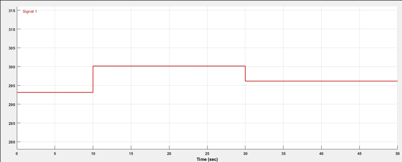
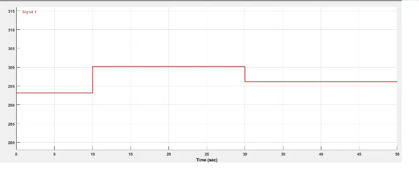
Objective: To maintain a temperature of 20 °C from 0 to 10 seconds, 27 °C from 10 to 30 seconds, 23 °C from 30 to 50 seconds.
Introduction:
A heat source is used in the system in order to increase the temperature. If the temperature is above 25 °C, the fan is turned ON to reduce temperature.
A thermistor is a resistance thermometer, or a resistor whose resistance is dependent on temperature. The term is a combination of “thermal” and “resistor”. It is made of metallic oxides, pressed into a bead, disk, or cylindrical shape and then encapsulated with an impermeable material such as epoxy or glass.
MODEL:
Link to the Model: https://drive.google.com/file/d/1upuJBnP1ZaBAg5CxWDEC6uqTvd1cEaKW/view?usp=sharing
Explanation:
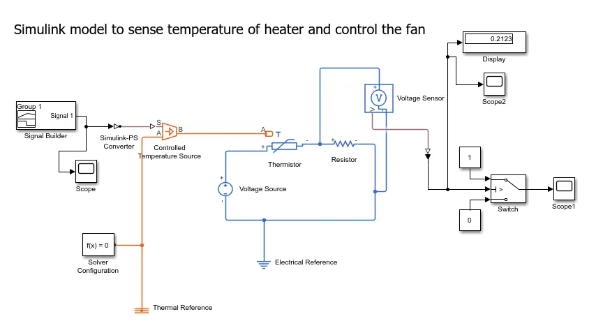
A signal builder is used to provide inputs to the heater according to the requirements. Signal builder creates and generates group of signals. The generated signals are converted into physical signal using Simulink-PS converter and inputs are filtered through it.
An ideal source of thermal energy to maintain specified temperature difference across the source is provided through the Controlled temperature source block. The solver configuration block provides the solver parameters required for simulation.
The thermistor and resistor are connected in series to a voltage source which are grounded through an electrical reference. The voltage sensor is connected in parallel to the resistor.
The output signal from the voltage sensor is converted into a simulink signal through a PS-Simulink converter. The output signal is used by the switch(1-0) to display the result using Display block.
Results:
Inputs to the Temperature Source
Scope1: After adding the switch
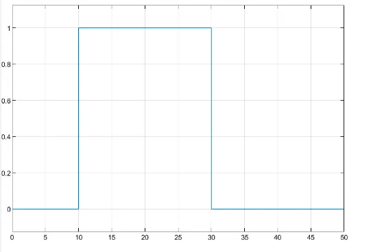
Scope2: Before adding the switch
Conclusion:
The model is simulated successfully and the temperature is varied according to the requirements.
The thermistor senses the temperature and accordingly if the temperature is above 25°C then the fan is turned-ON otherwise it is OFF.