Final Project: Electric Rickshaw modelling
Aim: To create a detailed MATLAB model of an electric rickshaw (three wheel passenger vehicle).
Introduction:
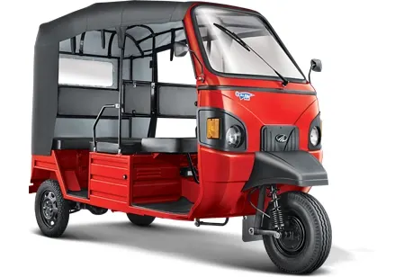
Electric rickshaws are small vehicles, with three wheels and use electric power from batteries to tun. They use an electric motor as engine which draws electric power from the rechargeable batteries installed in the rickshaw body.
They are like normal rickshaws but powered by electric motor instead of petrol or diesel motor.
Model:
Link to the Model: https://drive.google.com/file/d/1EAO0C-E4ne9tTfceeJ8cofvEUE0YwkV6/view?usp=sharing
Explanation:
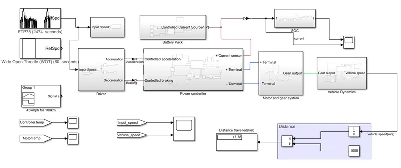
We have 6 different sub-systems in the Model,
- Driver
- Power Controller
- Battery pack
- SOC(State of Charge)
- Motor and Gear System
- Vehicle Dynamics
Driver:
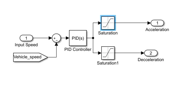
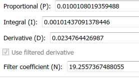
The input for the speed is taken from the drive cycle and is controlled by a PID Controller. The acceleration and deceleration of the vehicle with a saturation of 0.5 depends on the actual vehicle speed input into the system. The PID Values are set to default.
Power Controller:
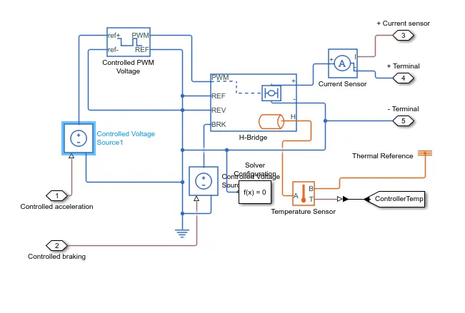
All the systems of the model are dependent of power and it has to be supplied in control. A power controller consists of a sine PWM voltage circuit, H-bridge circuit and a current sensor. The output voltage amplitude is set to 110V for PWM and the same is for H-Bridge.
Battery Pack:
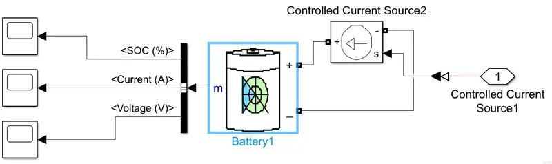
Lithium-ion battery is used for this model with a nominal voltage of 60V. The SOC of the battery reduces as the vehicle starts.
The power controller provides the input cuurent to the battery while charging. The SOC, current and Voltage are the parameters of the battery.
State of Charge(SOC):
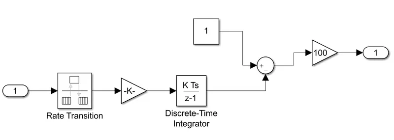
Rate transition handles data transfer between different rates and tasks. The SOC of the battery reduces as the vehicle starts and increase when the charger is connected.
Motor and Gear System:
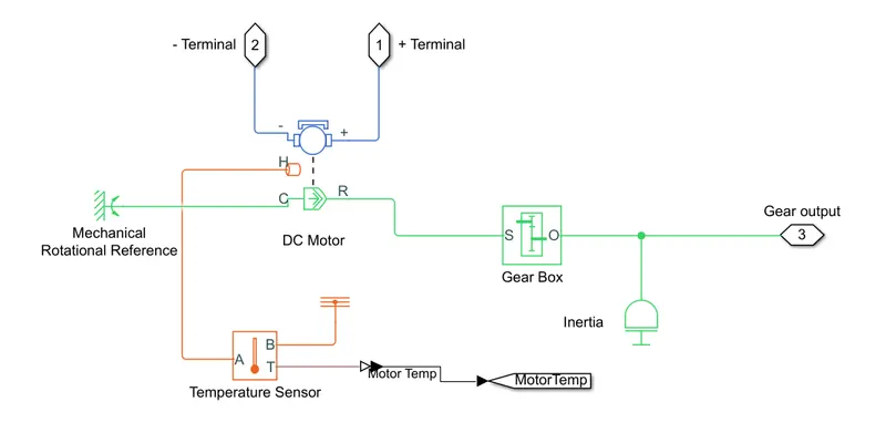
This system is a combination of Mechanical, Electrical and temperature components. In this model, we use a Permanent Magnet brushed motor to run the wheels. The gear box is connected to the transmission system and the temperature sensors checks the temperature of the motor.
Vehicle Dynamics:
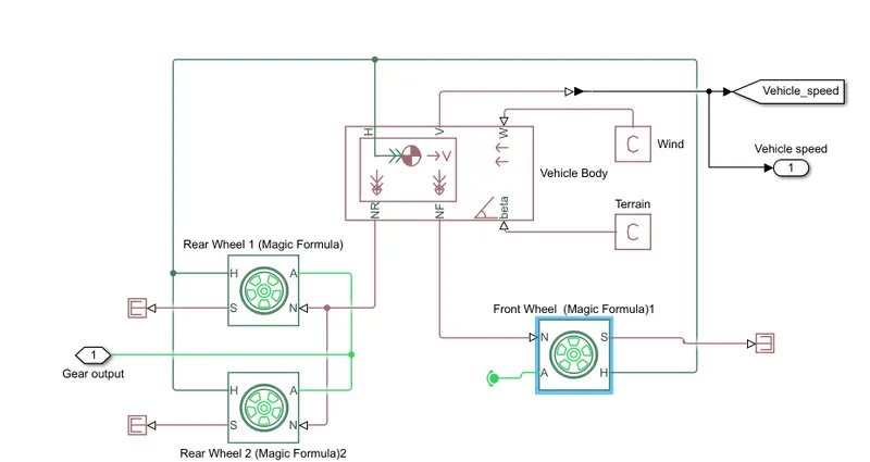
The transmission system is connected to the wheels of the rickshaw. A two axle vehicle body has the following parameters:
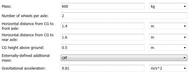

The gradeability and wind constants are set to 1.
Drive Cycles:
The model is made to run at 3 different drive cycles: FTP75, WOT and 45kmph for 100km drive cycles.
Result:
For FTP75 Drive cycle:
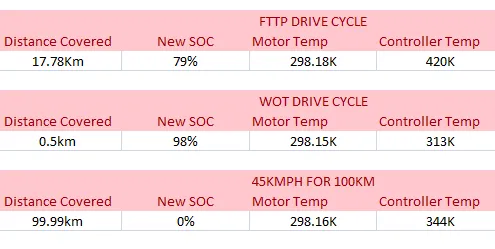
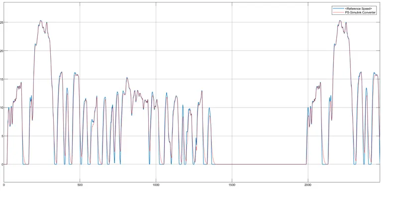
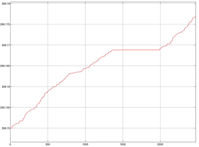
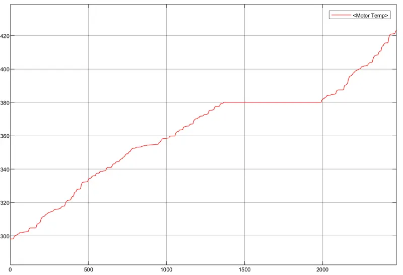
The distance travelled by the vehicle is 17.78km at the end of drive cycle. The SOC is dropped from 100% to 79%.
The plot for input speed and actual speed of vehicle:
Controller Temp:
Motor Temperature:
For WOT-drive cycle:
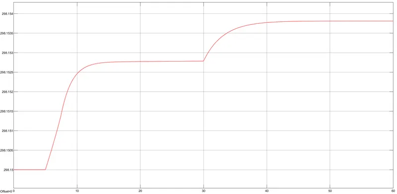
The distance travelled by the vehicle is 0.5km at the end of drive cycle. The SOC is dropped from 100% to 98% during acceleration and increases during braking.
The plot for input speed and actual speed of vehicle:
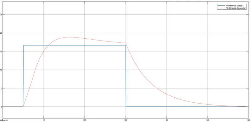
We can see that it takes some extra time to obtain the required speed.
Controller Temperature:
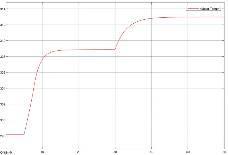
Motor Temp:
45Kmph for 100km drive cycle:
The distance travelled by the vehicle is 99.99km at the end of drive cycle. The SOC is dropped from 100% to 0%.
The plot for input speed and actual speed of vehicle:
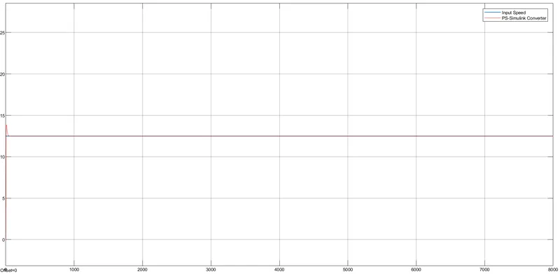
The input speed and actual speed of vehicle are same with a small lag during the start due to acceleration.
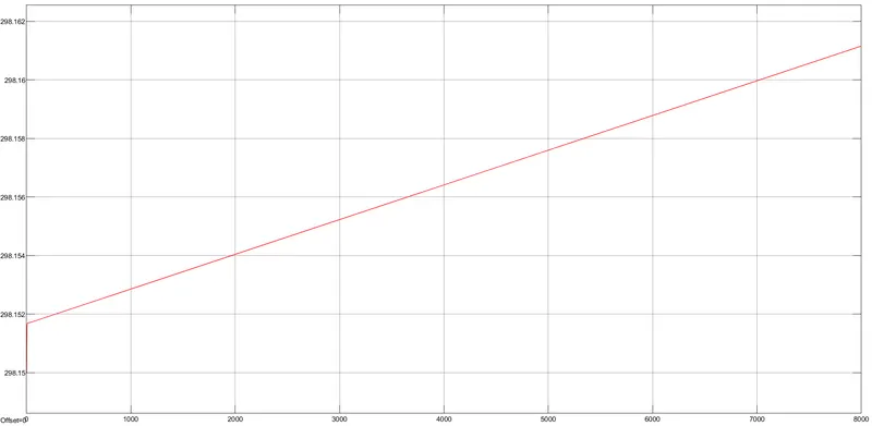
Controller Temp:
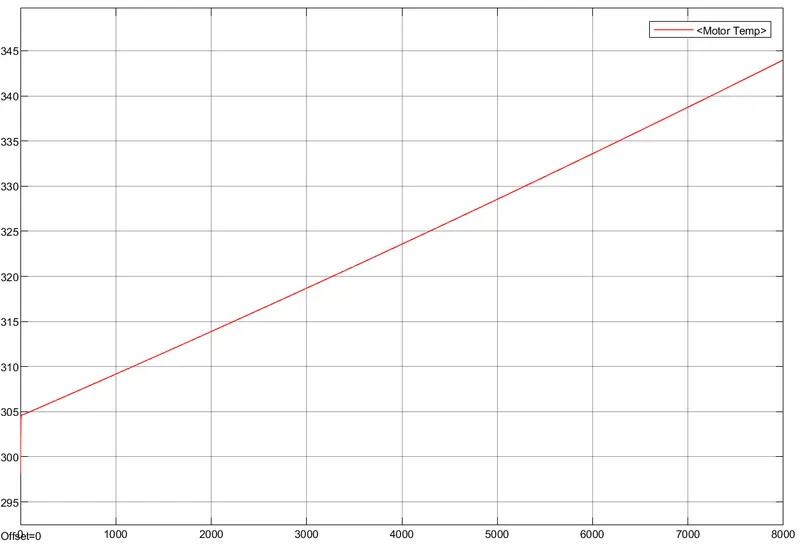
Motor Temp:
Conclusion:
The Electric rickshaw model is run for all the 3 drive cycles. The Motor temperature is always higher than the Controller temperature.
The Model runs efficiently with the FTTP drive cycle as there is not much accelaration and deceleration.