Week-11 Challenge: Braking
Aim: To calculate the energy required for braking.
Objective: To create a drive cycle and to calculate the total braking energy required.
Explanation:
Let us consider the following drive cycle,
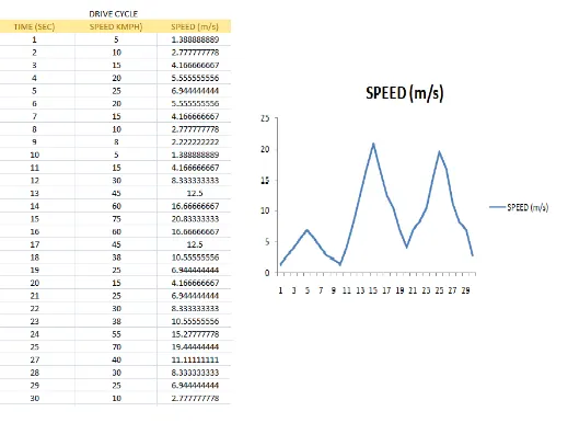
Here,
Mass of the Vehicle = 1000kg
For the first 10 seconds,
Top speed after acceleration, V2 = 25m/s
Lowest speed after deceleration, V1 = 5m/s
Braking energy required,
`BE_1 = 1/2*m*(V_2-V_1)^2`
`BE_1 = 1/2*1000*(6.94-1.38)^2`
`BE_1 = 15.5KW`
For the next 20 seconds,
`BE_2 = 1/2*m*(V_2-V_1)^2`
`BE_2 = 1/2*1000*(20.83-4.16)^2`
`BE_2 = 138.9KW`
`BE_3= 1/2*m*(V_2-V_1)^2`
`BE_3 = 1/2*1000*(19.44-2.77)^2`
`BE_3 = 138.9KW`
Total Braking Enery Required,
`BE_(Total) = BE_1 +BE_2+BE_3`
`BE_(Total) = 15.5+138.9+138.9`
`BE_(Total) = 293.3KW`
Result:
For this driving cycle, the braking energy required is 293.3KW.
Conclusion:
As the Velocity of the vehicle increases, more amount of braking energy is required.
Braking Torque of Electric Motor:
Aim: To study the behavior of braking torque at high speed of an electric motor.
Objective: To study why electric motor can’t develop braking torque at high speed similar to starting and to study how electric and mechanical brakes are coordinated in an Electric Vehicle.
Explanation:
Electric Motor can’t develop braking torque at high speed because the motor is runs at regenerative braking mode when the braking torque is small. With the increase of braking torque, motor speed keeps decreasing. If motor speed turns negative, the motor is working in the both regenerative & Mechanical braking.
Coordination of Electric and Mechanical Braking Systems:
Mechanical brakes are assemblies consisting of mechanical elements for the slowing or stopping of shafts in equipment drives. They use levers or linkages to transmit force from one point to another. Braking slows or stops the movement of the coupled shafts. There are several types of mechanical brakes: Disc brakes, Drum brakes etc.
Regenerative braking occurs when the motor run in the opposite direction to stop the vehicle and this also generates current, so it is called as Regenerative braking.
Mechanical brakes are applied when the regenerative braking is not supplying enough power to stop the vehicle. The two braking systems are controlled by an electronic system. A slight reduction in the car’s speed, determined by the driver’s force on the pedal, causes the vehicle’s electronics to activate the regenerative brakes and run the motor in reverse direction. If the vehicle needs to come to a quick stop, to avoid a collision, the mechanical brakes will be engaged. In this way, Electrical and mechanical braking systems are coordinated.
Conclusion:
At high speeds, the regenerative braking torque cannot be developed by the motor. If the regenerative braking force is not sufficient to stop the vehicle, the mechanical braking systems are activated.
Plotting Contour:
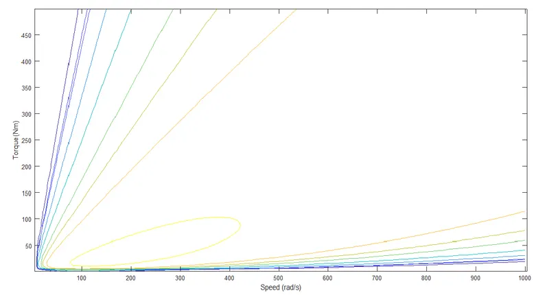
Aim: To write a MATLAB program which plots contour of given motor speed, torque and efficiency values.
Code:
% a MATLAB program to plot contour of given motor speed, torque and efficiency values.
clear all
close all
clc

%Speed and Torque inputs
speed = linspace(1,1000);
T = linspace(1,500);
%Losses:
%copper loss
kc = 0.1;
%iron loss
ki = 0.0018;
%motor constant loss
C = 20;
%windage loss
kw = 0.00001;

[x,y] = meshgrid(speed,T);

%Output power = speed*Torque
Pout = (x.*y);

Copper = (y.^2).*kc;
Iron = ki*x;
Windage = (x.^3).*kw;

%Input power
Pin = Pout + Copper + Iron + Windage + C;
%Efficiency = output/input
efficiency = Pout./Pin;

E = [0.65,0.69,0.70,0.75,0.80,0.85,0.88,0.91,0.96];
contour(x,y,efficiency,E);
xlabel('Speed (rad/s)');
ylabel('Torque (Nm)');
hold on
Result:
The plot contours for given motor speed, torque and efficiency are obtained.