Week 7 State of charge estimation
Aim: To study the Battery Management System by closed loop simulation of a MATLAB Model and understand coulomb counting.
Model:
Explanation:
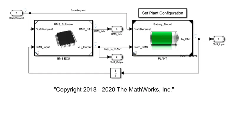
The Electronic Control unit(ECU) of a BMS consists of State Machine, SOC Estimation and cell balancing.
The State machine controls all the state variables of the pack and the SOC calculation is done in two ways: Coulomb counting and unscented Kalman filter(UKF)/Extended Kalman filter. The balancing logic of the cell is done by considering the min. and max.Voltages of the cell input and output.
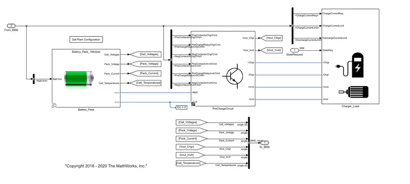
The plant consists of main subsystems i.e, Battery pack, PreCharge circuit, Motor(load) and charger.
Battery Pack:
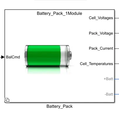
Battery pack consists of two types of modules: one module consists of six cells connected in series providing high voltage. The other module consists of 16 individual modules with 6 cells each connected in series.
The outputs of the pack include Cell Voltage, pack voltage, pack current and cell temperature.
PreCharge circuit:
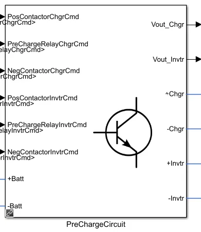
It helps in the proper operation and protection of components in high voltage applications. Also it will help for the increased life cycle of the battery.It consists of positive and negative contactors for charger and inverter. A voltage sensor is placed so that there is a controlled voltage output.
Load and charger:
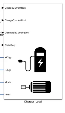
A state request sends commands to the motor and the charger to connect/disconnect. The other connections are for positive and negative terminals for charging.
Coulomb Counting:
The Coulomb counting method measures the discharging current of a battery and integrates the discharging current over time in order to estimate SOC.
To determine available capacity, coulomb counting relies on the integration of the current drawn from and supplied to a battery over time, τ∈t0t, as given by
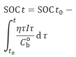
where I is the current and η is the efficiency during charge and discharge operations.
In BMS Model the coulomb counting is implemented as follows:
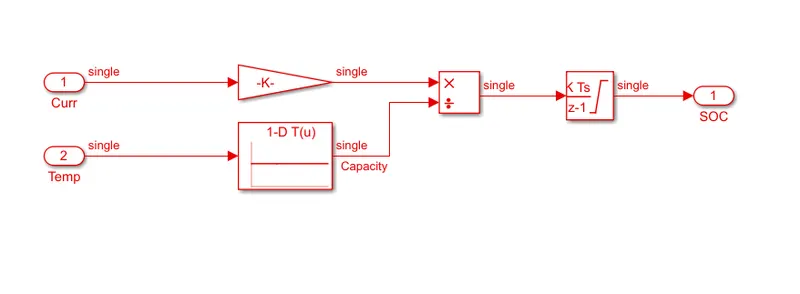
The current is taken in each time step and is divided by the capacity of the battery. A 1-D lookup table is used as input, the discrete time integrator block integrates the values and provides the State of charge output.
Advantages:
- Process is very simple
- Output is close to real value
- Cheap to implement
Disadvantages:
- Requires external values to estimate the current
- Various factors of the cell have an effect on output
- Hysteresis behaviour is not considered.
Test cases:
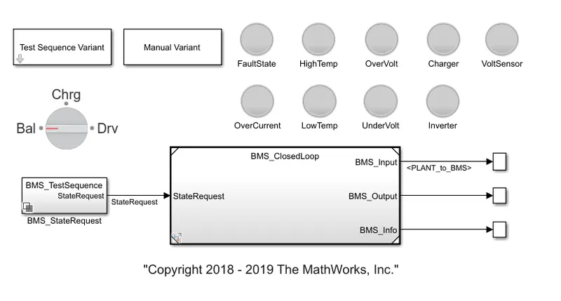
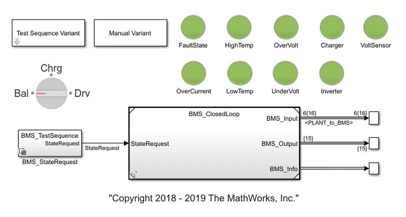
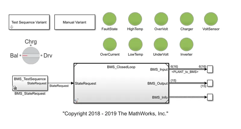
We need to simulate the model 3 times from harness dashboard and the results are observed for each case. This is done through the test sequence variant block in the harness dashboard.
Results:
Case-I:
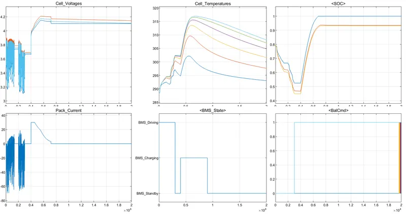
Driving : The cell voltages fluctuate between 3.1V to 3.8V when the cells are discharging, also the pack current reduces and SOC is reducing gradually as the system is extracting current from the battery. The temperature is under normal range(300K) and the cell balancing is not activated.
Charging: The cell voltage is increased from 3.7V to 4.2V and there is sudden increase in cell current as the cell is charging. The cell temperature and the SOC is increasing linearly as current is being supplied and the cell balancing gets activated.
Standby: The cell voltage, cell current and the SOC are stable. The cell temperature is reducing gradually as load/charger is disconnected and the cell balancing gets activated.
Case-II:
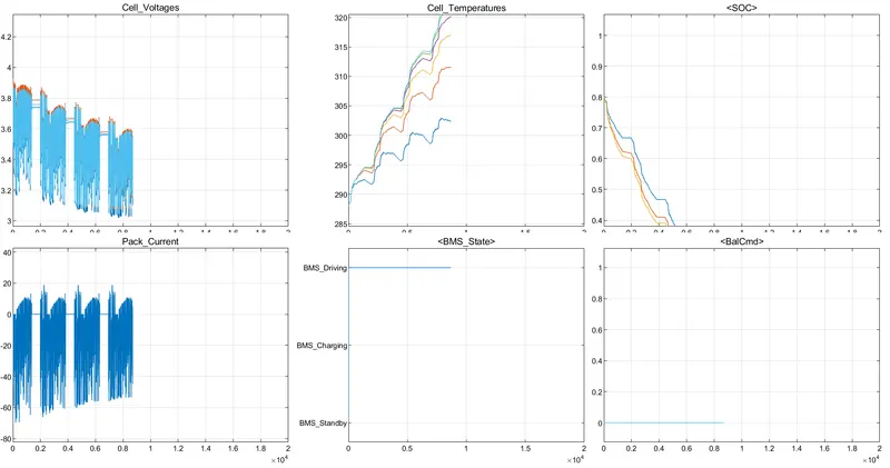
The cell voltages fluctuate between 3.0V to 3.9V when the cells are discharging, also the pack current fluctuates and SOC is reducing gradually from 80% to 0% as the system is extracting current from the battery. The cell balancing gets activated and the simulation stops as the battery has been completely discharged.
Case-III:
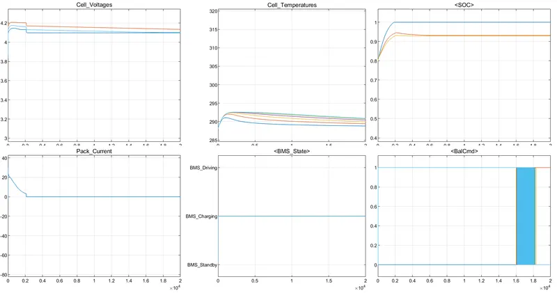
The cell voltages increases as the charger is connected and the voltage is constant and the SOC is 100% after 2000seconds. The pack current reaches its peak value at the start and later becomes stable. The cell temperature increases at the start and is under control after 5000seconds and the balancing logic varies between 0 to 1 before the end of the cycle.
Conclusion:
The cell voltages and cell current reduces while the battery is discharging. When the cell is at standyby mode, the cell voltage, cell current and the SOC are stable. The coulomb counting is the most simple method of estimating the SOC and is used in the BMS.