Thermal modeling of EV Battery Pack
Aim: To simulate the thermal effects and compare life cycle performance of a 10 cell series lithium ion battery model at various temperatures, charge & discharge rates using MATLAB.
Objective:
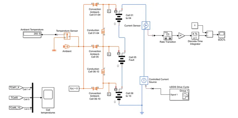
To create a model containing ten cells in series that are connected to a temperature source. This is done in order to study the behavior of State of Charge(SoC) of the battery pack at different temperature.
Model:
Explanation:
Operating voltage of a Battery pack of an EV can be varied by connecting several cells in series, with each cell adding to the total terminal voltage. Parallel connection attains higher capacity for increased current handling, as each cell adds to the total current handling. Some packs may have a combination of serial and parallel connections.
As we require a higher voltage battery pack for our model, we are connecting the cells in series. The cells are split in 3 groups: cell(01-04), cell-05 and cell(06-10) while cell-05 indicating the fault condition.
A weaker cell causes an imbalance especially in a serial configuration and a battery is only as strong as the weakest cell. In this model, cell-05 is a weak cell causing an imbalance in the pack. It can be noted that a weak cell will cause a variation in SOC and we can know it by simulating this model. A fault cell could cause excessive heat and become a fire hazard for the battery pack.
Batteries generate heat during charge and discharge due to enthalpy changes, electrochemical polarization and resistive heating inside the cell. Temperature variation inside the batteries can lead to uneven temperature distribution which creates uneven charge/discharge behaviour within the pack. Thermal runaway may occur in a cell when heats are not properly control and possible to cause fire and explosion. For these reason, the need for battery thermal management is necessary for a EV battery pack to keep the battery at its optimum performance.
We have ten Li-ion cells connected in series to a current source. The temperature of each cell is sensed by a temperature sensor also a sensor is placed to check the ambient temperature. Convective heat transfer occurs between the cells for ambient temperature reference and conductive heat transfer occurs between cells to check the actual cell temperature.
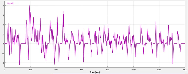
A UDDS drive cycle is implemented to know the behaviour of cell at different speeds and the SOC of the entire pack is obtained.
The cells in series are divided into 3 groups: cell(01-04), cell-05 and cell(06-10). The cell -05 is at fault condition. We are going to simulate and observe what is happening to the cell temperature for each cell group and the SOC.
The UDDS drive cycle implemented for this model is as follows:
Results:
The SOC of the cells:
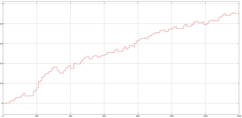
The SOC of the cells is increasing gradually from 0 to 0.9 as current is being supplied. The SOC is 90% at the end of the end of the cycle.
Cell temperatures for different cell groups:
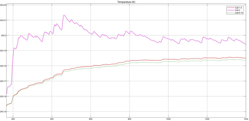
The cell temperature of cells(0-4) is increasing gradually from 0-600seconds and is stable from 600 to the end of the cycle. The cell temperature for cells(06-10) is same as cells(0-04) with a slight larger value.
Since the cell-05 is at fault, the cell temperature increases suddenly and reduces after 600 seconds. This also affects the SOC as the SOC is varying after the cell temperature is increasing.
The temperature of all cell group is always higher than the ambient temperature during the cycle.
Conclusion:
We can conclude that when the cell is at fault condition its temperature rises with time and cause an imbalance in the battery pack and affects the SOC of the pack.
If the battery pack is not managed or the fault condition is not solved then it will lead to increased heating of the cell and will lead to a fire hazard.
The battery performance is highly affected by the fault cell and continued charging and discharging will lead to degradation of the battery very soon.