Week 11 - Final project
OBJECTIVE:
Creation of CAD model considering following inputs as like in OEM and tier1 companies
- a) Class A surface
- b) Nominal thickness : Refer master sections
- c) Attachment strategy :
Find a attachment strategy for the door panel complete work.
Use Push pin with Dog house for Lower substrate – Door panel attachment
Use heat stakes for part to part attachment
Output required:
- Create thickened part using master section for reference
- Create the mounting features as per design guidelines in the industry and with master sections
- Apply material details :
- Draft analysis & Tooling analysis
- Creation of parting lines and check tooling feasibility
DOOR LOWER SUBSTRATE
CLASS A SURFACE
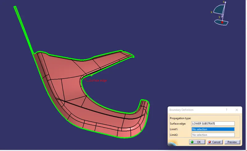
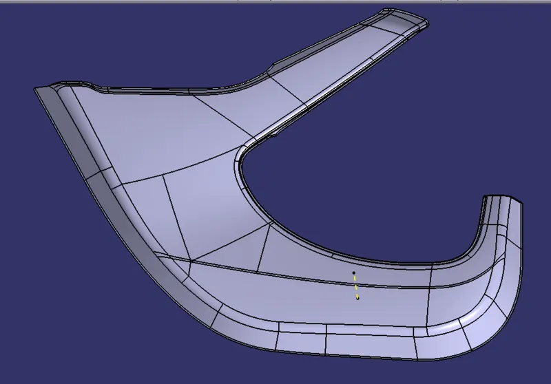
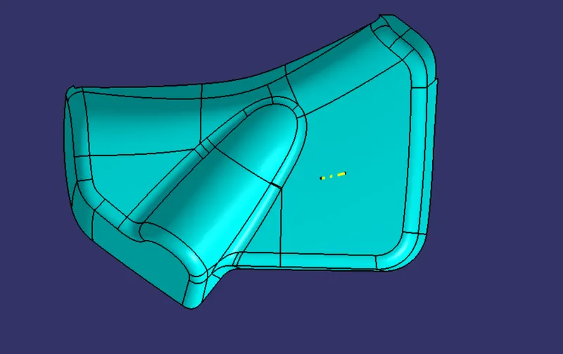
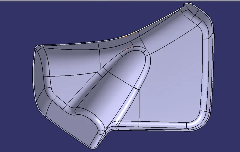
THE FIGURE BELOW IS OF GIVEN CLASS A SURFACE OF THE LOWER SUBSTRATE.
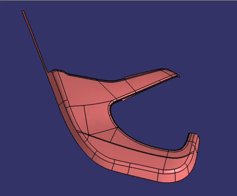
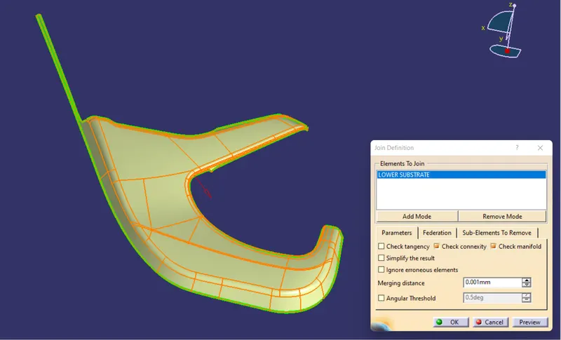
FIRST WE HAVE TO CHECK THE GIVEN CLASS A SURFACE ,HOW IT IS.
(1) WE CAN DO IT BY THE HELP OF THE JOIN COMMAND OR BOUNDARY COMMAND.AS SHOWN BELOW IN THE PHOTOS.
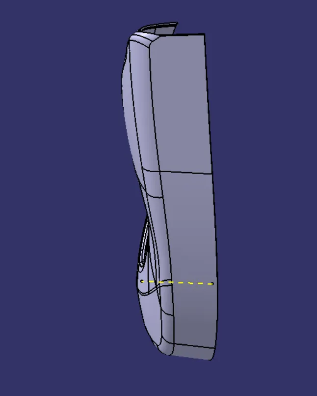
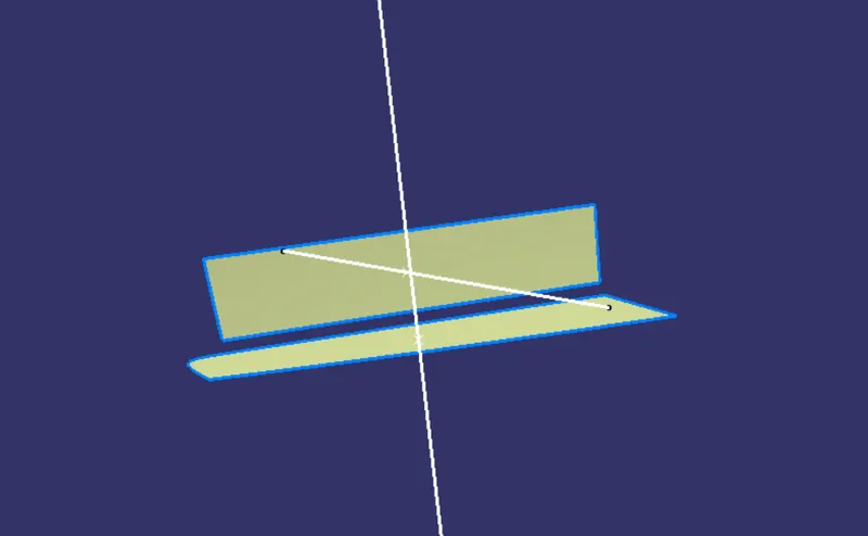
CREATION OF TOOLING AXIS
1. FIRST EXTRACT THE SURFACE WHERE WE WANT THE TOOLNG AXIS.
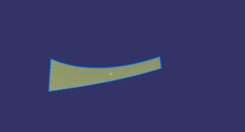
2. MAKE A POINT IN THE MIDDLE OF THE SURFACE.
3. DRAW A LINE NORMAL TO THE SURFACE.
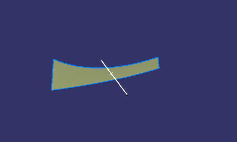
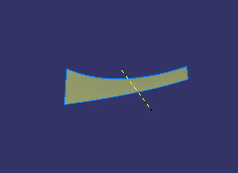
4. WE GET DESIRED TOOLING AXIS. AS SHOWN IN THE FIGURE BELOW.
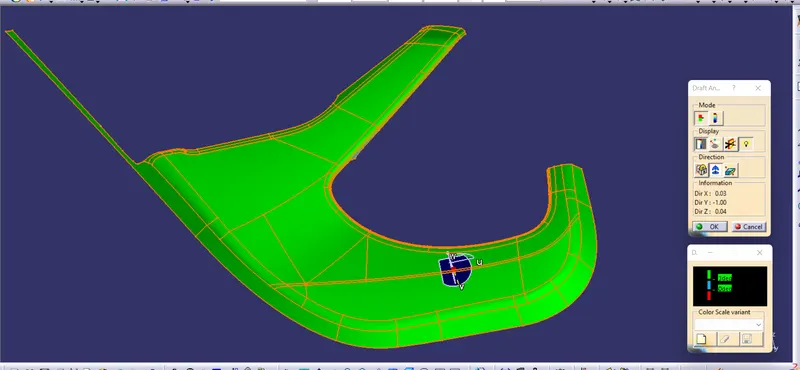
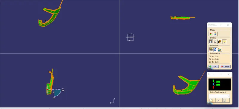
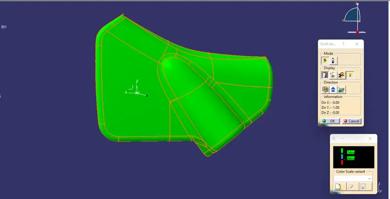
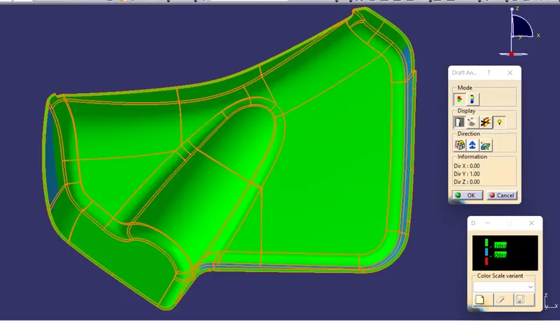
DRAFT ANALYSIS OF THE GIVEN CLASS A SURFACE WITH RESPECT TO THE TOOLING AXIS.
1. GO TO THE INSERT TAB AND THEN CLICK ON THE ANALYSIS TAB
2. AFTER THAT CHOOSE THE DRAFT ANALYSIS TAB .
3. CLICK ON THE COMPASS COMMAND IN THE WINDOW OPENED AFTER THE DRAFT ANALYIS TAB.
4. MOVE THE COMPASS ON TO THE THE TOOLING AXIS
5. LOCK THE COMPASSS ON THE TOOLING AXIS.
6. CLICK ON THE SURFACE .
7.RED COLOR SHOWN THE NEGATIVE DRAFT .
8. CYAN COLOR SHOWS THE DRAFT ANGLE BETWEEN THE 0 TO 3 DGEREE.
9. GREEN COLOR SHOW THE SURFACE WHICH ARE CLEARED BY THE TOOLING AXIS.
CREATION OF B SURFACE.
1. FIRST MEASURE THE MASTER SECTION. ACCORDING T0 THAT WE WILL OFF SET THE CLASS A SURFACE.
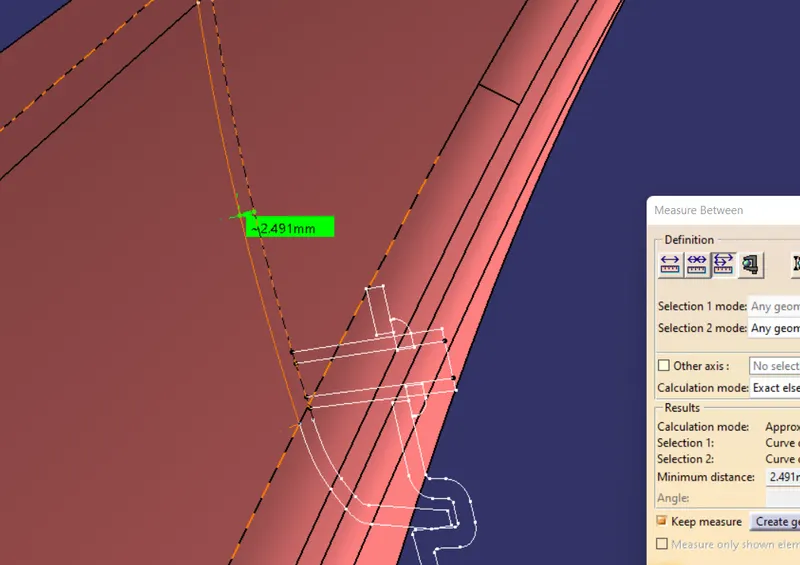
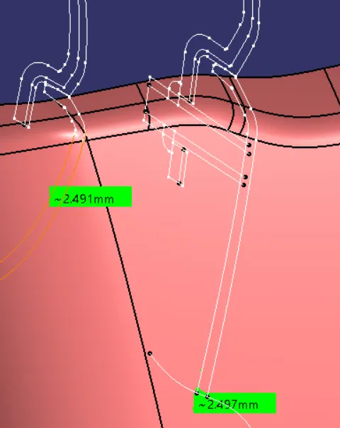
IT IS SOMEWHERE 2.497 AND SOMEWHERE 2.419 mM. IN MY CASE . SO IO HAVE OFFSETTED THE CLASS A SURFACE 2.497mm IN THE INWARD DIRECTION.
SUFACE WE GET AFTER OFFSETTING THE CLASS A SURFACE.
IN MY CASE I HAVENT GOT ANY PATCHES .
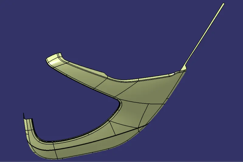
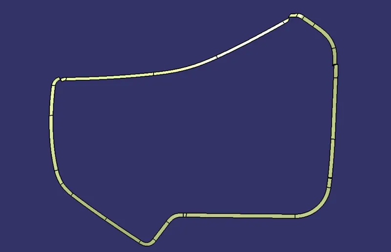
I HAVE EXTRACTED THE BOUNDARY FIRST TO SPLIT THE EXTRA PORTION WE HAVE.
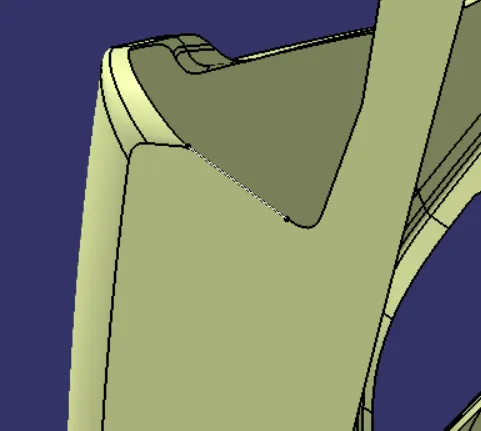
AFTE RTHAT I HAVE EXTRAPOLATED THE EXTRACTED BOUNDARY TO PERFORM THE SPLIT OPERATION FOR THE EXTRA PORTION WE HAVE.
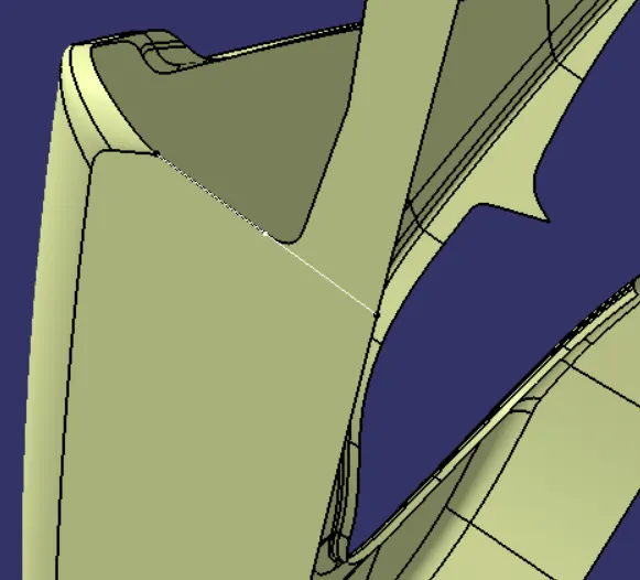
SPLIT OPERATION
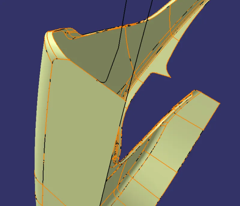
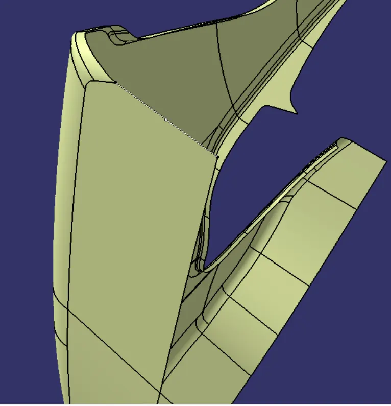
FINAL B SURFACE
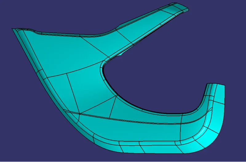
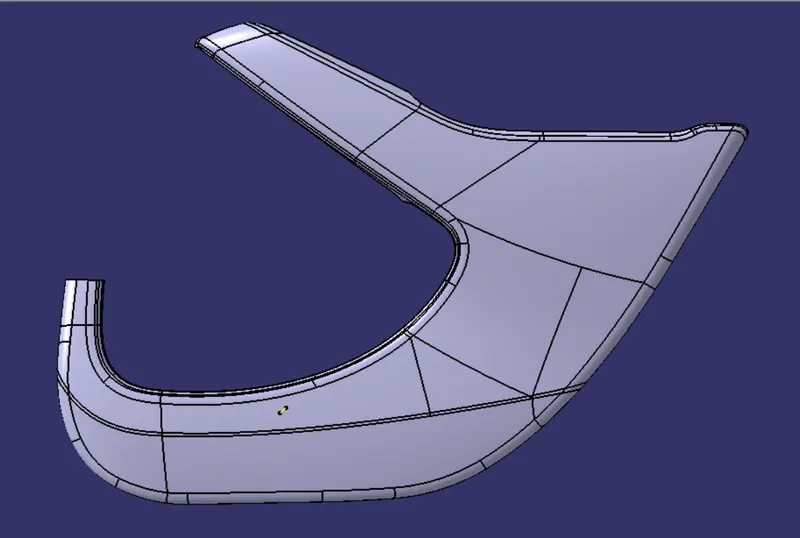
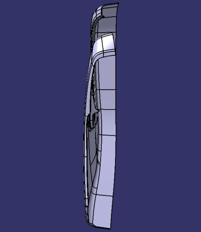
A+B+C
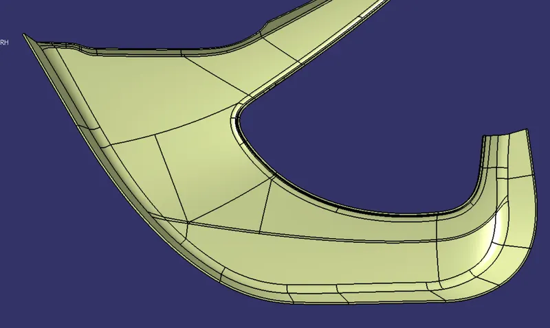
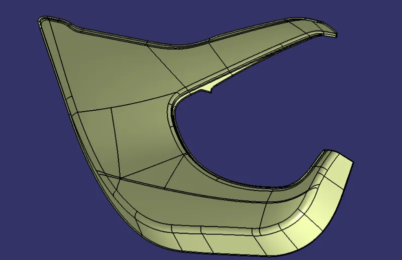
FINAL PRODUCT
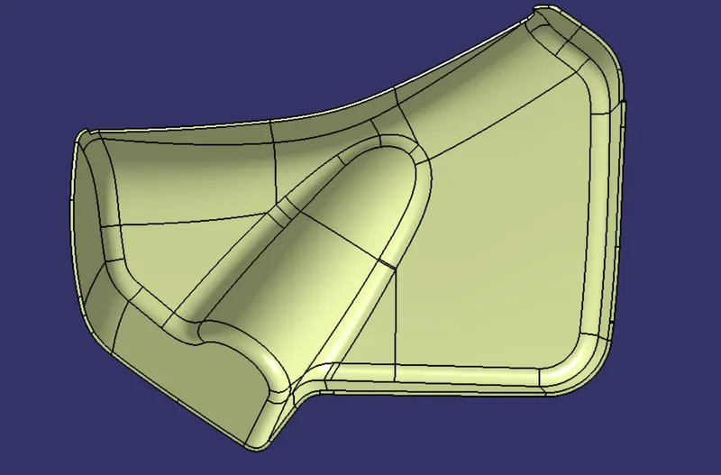
1.AFTER THESE GO TO PART DESIGN WORKBENCH
2.CLICK ON THE COMMAND OF CLOSE SURFACE AND CHOOSE THE A+B+C SURFACE . WE GET THE CLOSE SURFACE.
AS SHOWN BELOW.
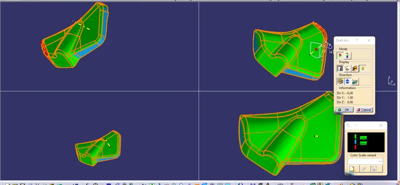
DRAFT ANALYSIS OF FLASTIC PRODUCT
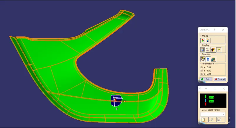
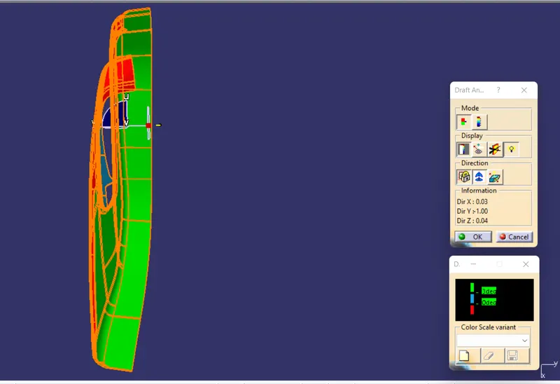
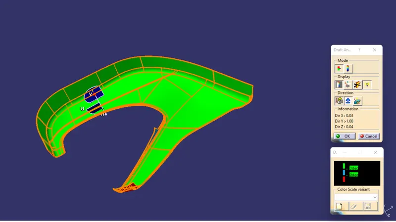
BOTTLE HOLDER
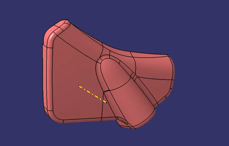
ARM REST
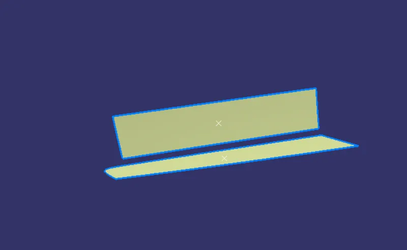
CREATION OF TOOLING AXIS
1. FIRST EXTRACT THE SURFACE WHERE WE WANT THE TOOLNG AXIS.

REQUIRED TOOLING AXIS
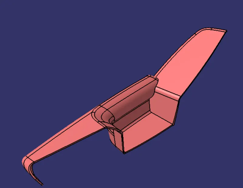
ARM REST AFTER MAKING CLOSED PRODUCT
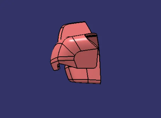
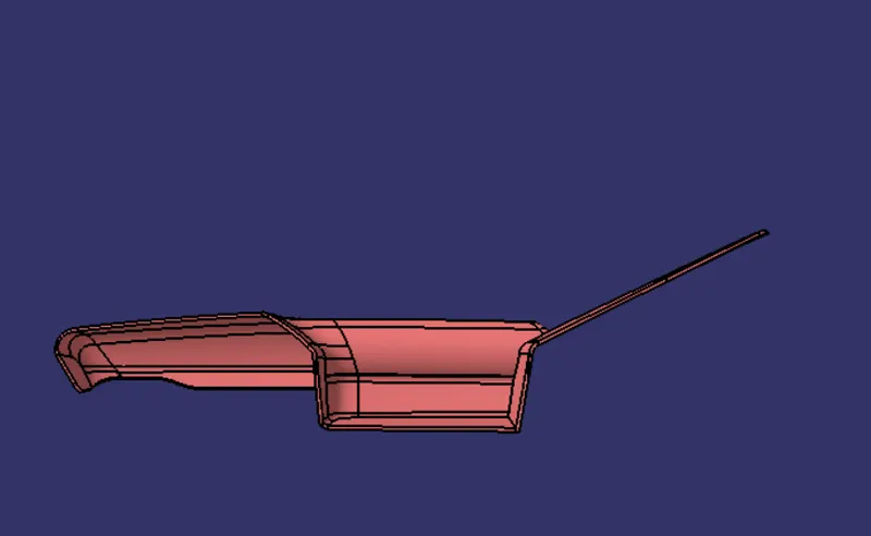
MAP POCKET
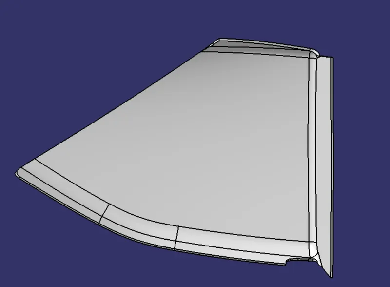
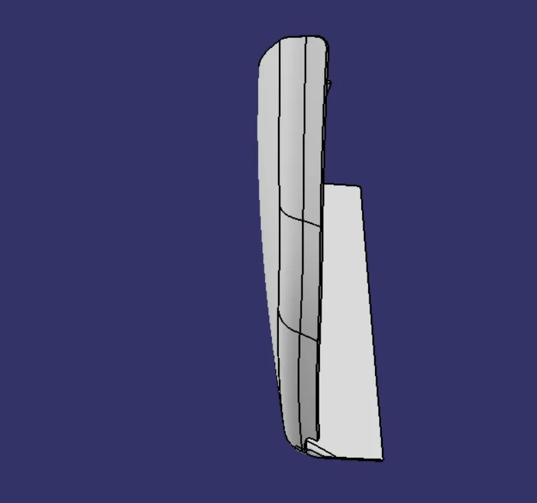
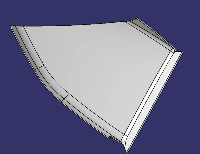
FINAL DOOR TRIM
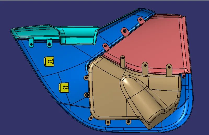
B SIDES FEATURES
HEAT STAKES
- Heat Staking is a pulsed-heat process to join two or more parts out of which one at least is made of plastic.
- The process is to deform the plastic material using heat and force at a set process time.
- The bond is made by partially de-forming the plastic part in order to fix the other.
- Heat Staking makes it easy to bond metal to plastic and is commonly used in high volume/low cost applications such as automotive, IT and consumer appliances.
- Similar and dissimilar materials may be joined: metal to metal, plastic to plastic, metal to plastic
- Accurate control operating within a small process window
- Local heating resulting in no damage to surrounding materials
- Processing of glass-filled materials
- No mechanical vibration
- Many heat-stake shapes possible through custom designed tools.
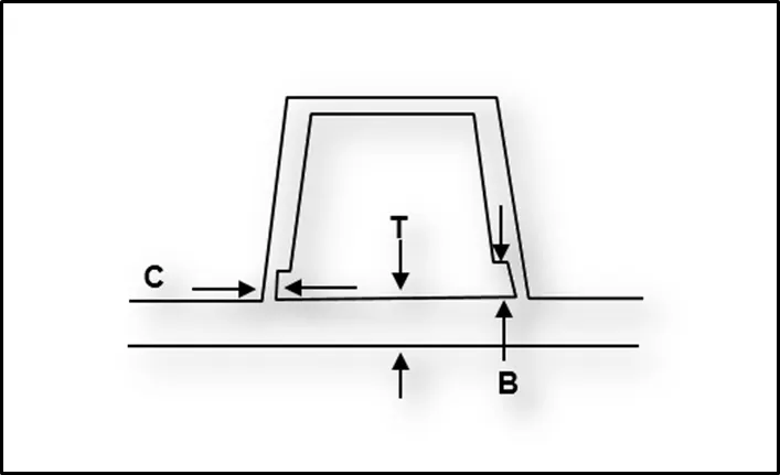
DOGHOUSE
- Dog house is the attachment feature which helps you to assemble things at certain heights and also resolve the plastic defects.
- There are plenty dog house design which can be used for assembly purpose but we will be using the one provided to ous by the resources.
- The master section or the enginnering drawing must be followed for creating the dog house.
PUSH PINS
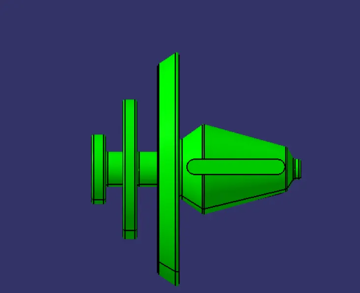
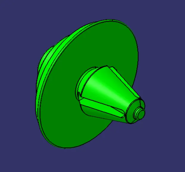
- These pins are used for the assembly purpose .
- These pins are guided into the sheet metal body.
- The pin is assembled over the dog house on one side and other into sheet metal.
#FLANGES ON THE COMPONENT
- These flanges will be build on the components for the fittment purpose with lower substrate.
- The hole at center will be guided along the heat stakes.
- Later top portion of the heat stake will be melted over it.
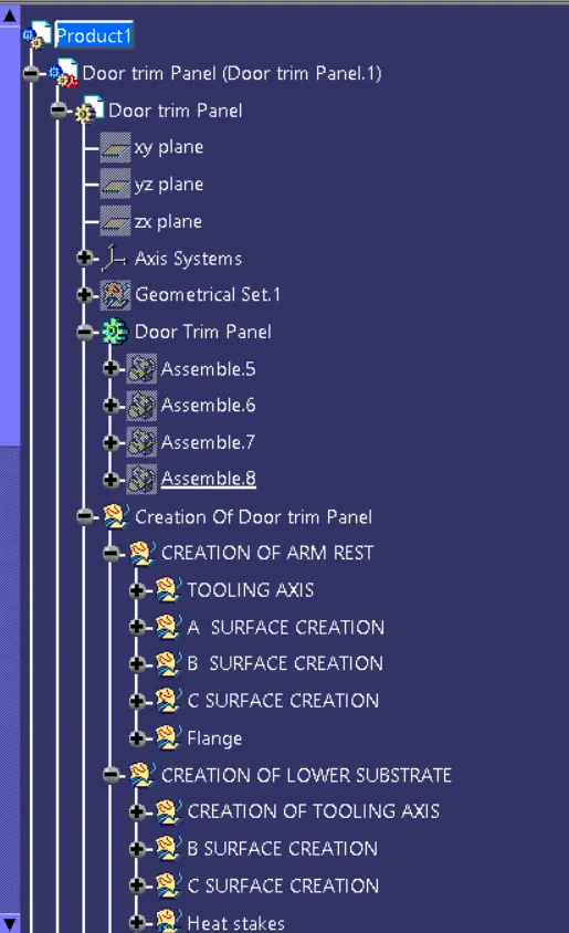
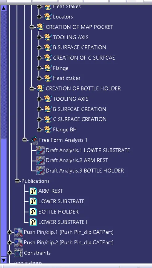
FEATURE TREE