Week 10: Project 1 - FULL HYDRO case set up (PFI)
Full- hydro setup
After no hydro simulation is run and successfully set up, then:
Case Setup for Full hydro setup for Port fuel injection engine:
Select ‘Parcel simulation’ in materials section. With this we select the material of which the parcels are made up of. Select ‘IC8H18’ in pre -defined liquids because isooctane has physical properties like viscosity, surface temperature, heat of vaporisation similar to that of gasoline.
Choose IC8H18 under query available list under ‘Parcel’ option in ‘Species’ column.
Enable ‘Spray modelling’ under physical models. Choose the option of ‘Parcel getting distributed evenly throughout the cone’ and ‘O’rourke model’ in turbulent dispersion. Turbulence fluctuation affect droplet characteristics.
We use the evaporation model here and tin source we select ‘2-source all base parcel species’ so that the liquid IC8H18 fuel is converted into IC8H18 gas based fuel.
Maximum radius for ODE droplet heating:1000
We consider a parcel of sphere shape and outer temperature is hotter than the inside temperature. When we take a parcel made of several drops , we see only one temperature value. We descritize the droplet and create individual finite vol cell and solve the ODE on each cell. This takes time. Max radius for ODE droplet heating is a limit or cut off radius where drops having radius lower than this radius value are considered small droplets and thus ODE is not solved for them and one temperature value is taken. The drops having radius value more than this value are considered big enough for ODE to be solved for them and they are descritized. This slows the simulation time also hence in our simulation , we take a size of this radius bigger than our actual drop size so that ODE does not need to be solved for any case.
We use a ‘NTC collision model’ having a ‘ post collision outcome’ option. We use a collision mesh and it is advisable to select the ‘ dynamic drop drag mode’.
Wall-film should be there on the walls of cylinder after spray , hence spray wall interaction mode should be’ wall-film’.
Film-splash model- ‘O’ Rourke model’ (advisable for gasoline engines).
Inside the injector option in spray modelling, we add IC8H18 as the injected species and make a trapezoidal profiled rate shape . This is just the profile in which the total fuel will be injected within the time .
We use the solid cone models in both the diesel and petrol engine system and only use the hollow cone model when we have empty spray in a pressurised swirled injector . We use kelvin helmhotz model and Rayleigh taylor model , the values that need to be entered in these and found by using recommendation for the Gasoline PFI under the ‘get recommendations’ option and a discharge coffecient of 0.8.
The injection is done in a ‘cyclic’ manner and start of injection (-480 deg) and injection duration (191.2 deg). Total injected mass is 3e-05 kg per stroke found as in the formula with help of fluid flow rate.
|
rpm |
3000 |
|
|
rps |
50 |
|
|
1 sec |
18000 |
degrees |
|
1 stroke |
720 |
|
|
stroke in one sec |
25 |
|
|
one stroke takes |
0.04 |
seconds |
|
fuel flow rate |
7.50E-04 |
kg/sec |
|
fuel flow in one stroke time |
3.00E-05 |
We put 4 nozzles with diameter as 250e-06 and using the given values of center of nozzle and spray axis.
After this combustion modelling should be done, combustion should start few crank angles before spark(at -15 deg) , it starts at -17 deg and ends at 130 deg. Name of fuel species as IC8H18 is inputed.
Enable sink/spark modelling in physical models and add 2 sources of type sphere. Both having energy as 20 MJ each but one has duration from -15 to -14.5 deg and other has all the time from -15 to 5deg, i.e. at the starting we have a high net energy of 40 MJ for 0.5 deg, which is the breakdown stage of the spark when energy is needed to conduct the energy through the spark gap.
Also we can add small and big embedding for this spark area for radius 0.001 and 0.003 respectively. This is done along with embedding in injector of type ‘injector’ with a scale of 4.
Hence, Case set up is done, simulation is run in cygwin and then files are post processed.some important line plots are:
Line Plotting:
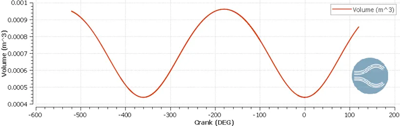
Volume for the combustion chamber region:
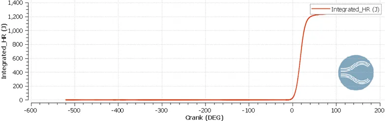
Integrated Heat release:
Compression Ratio:
Max volume:0.000573944
Min Volume:5.87457e-05
Max Volume/Min volume=9.76997:1
Combustion Efficiency:
Integrated heat release- 1240Joule
LHV=44.651MJ/kg
Energy content of fuel=3e-05 kg (per stroke)
Combustion efficiency=Integrated heat release/(LHV x energy content of fuel)
Combustion efficiency =92%
Work from engine performance calculator= 468.646N-m
Power:
Power =Work /time
One stroke takes 0.04 seconds, so Power required per stroke is 11.716 kJ/sec
Power=2*3.14*N*T/60
Torque:
T=Torque=37.312 J/sec
Crank Angle at
Ca10=6.83717
Ca50=18.4623
Ca90=31.701
It tells us the crank angle at which that percent of fuel has burnt successfully. This can help us to find if rate of fuel burning is faster or slower or appropriate.
Wall heat transfer Model: wall heat transfer model i.e. Law of wall is used in temperature so that more accurately the temperature can be found although the temperature can be inputed without law of wall also, which would give less finer results.
Observations:
Mesh image:
Cylinder head:
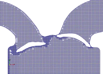
Embedding near valves:
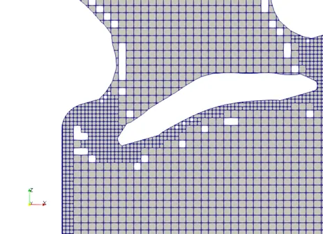
Near inlet port:
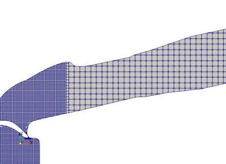
Cylinder:

Time at end of time step:
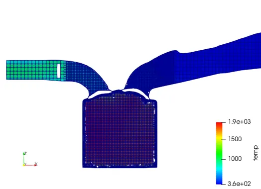
Velocity Animatio Link:
Conclusion:
Hence, full hydro simulation of port fuel injection system is set up and results and valve movement resembles with the theory.Although this a engine for practise simulation but results like compression ratio is within the range of gasoline fuel and also the combustion efficiency of engine is very high .Thus the full hydro setup for port fuel injection is perfomed.