Week 6 - CHT Analysis on a Graphics card
Conjugate Heat Transfer Analysis on Graphics card
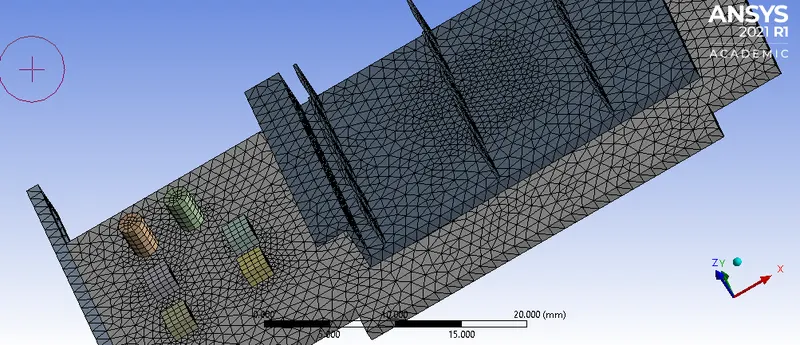
Parts of graphics card-fin,processor,base. Processor is the heat source and fin tray is setup to increase surface area for a faster heat transfer. The simulation is ran as follows:
Geometry- Once geometry is imported, share the topology (click on top of component branch and choose share option in topology). Workbench>share
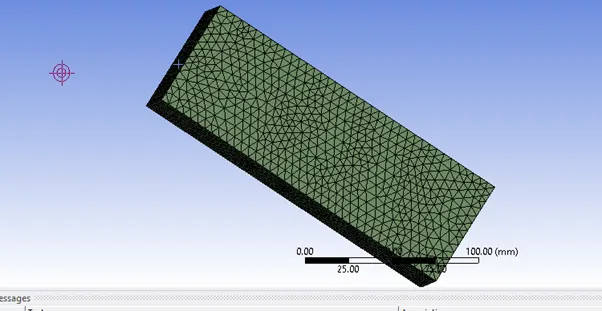
Mesh- Mesh of 5mm is generated for this simulation. Body sizing for the fin and the base is 1 mm and for processor is 0.5mm. Along with body sizing , one should always give value to ‘max size’ in sizing under mesh , here 5mm. Global and local mesh sizing value should be co-ordinated with each other.
Setup- The simulation is performed for 3 velocities- 1,3,5m/s.
Basic- steady state solver, pressure based, absolute velocity, temperature equations taken in consideration hence choose temperature box, k-Epsilon model is chosen.
Creating materials-
Fluid-air, solid- Plastic, Silicon, Aluminium (from the solid category of materials)
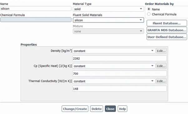
Silicon thermal conductivity-148W/mK
Silicon Density-2.3292 g/cm3=2329.2kg/m3
Cp=0.7J/gC
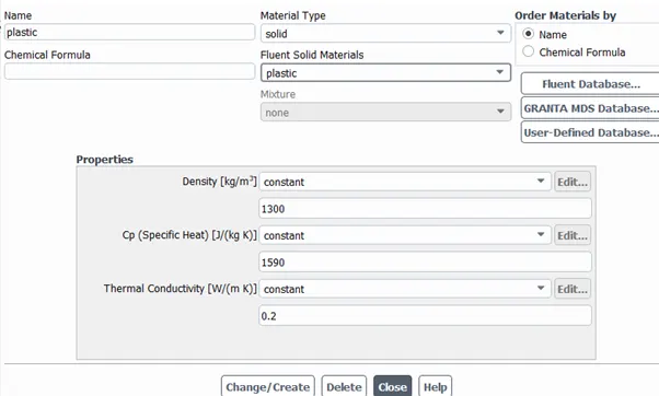
Bakelite density-1.3g/cm3
Thermal conductivity-0.2W/mK
Cp=1.59kj/kgK
Input in cell zones
Base-Solid- Plastic material
Domain-Fluid- Air material
Fin-solid-Aluminium material
Processor-Solid-Silicon Material
Source term-1 no. constant heat source for 1watt per unit volume
Volume of processor-64mm3
Source term value(W/m3)=15625000
Boundary Values-
Inlet- Input the velocity, temp as 273K.
Reference values (from inlet):
Area- 4 walls of processor – 32e-06
Length-20mm
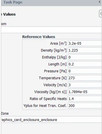
Hybrid Initialization Done.
Give a contour for temperature and make report for wall adjacent heat transfer coefficient.
Type of report with explanation: Wall adjacent temperature coefficient, Surface heat transfer coefficient, y plus heat transfer coefficient (inside wall fluxes option)
Choose the 4 walls of processor for these reports(not top and bottom).
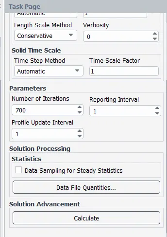
Run Calculation:
Results for setup:
Velocity-1m/s
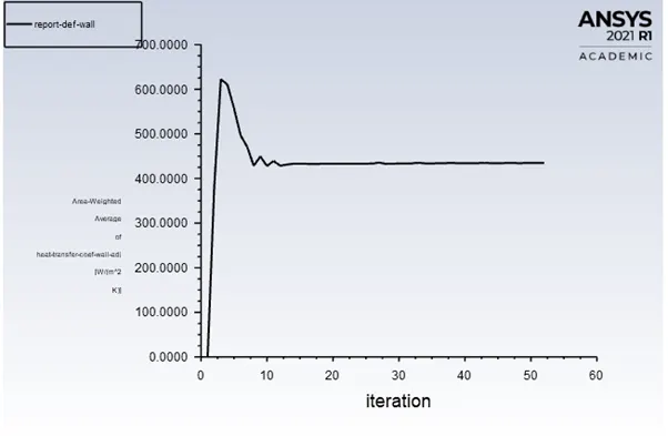
Wall-adjacent heat transfer coefficient-434.507W/m2K
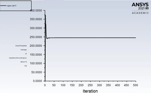
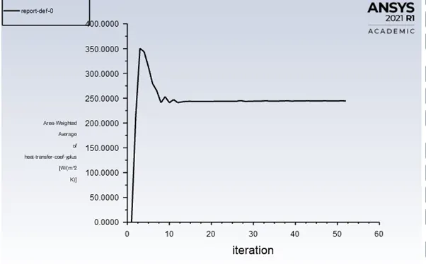
Y+ transfer coefficient-244.5w/m2k
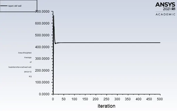
Yplus transfer coefficient:
Max temperature achieved-298K
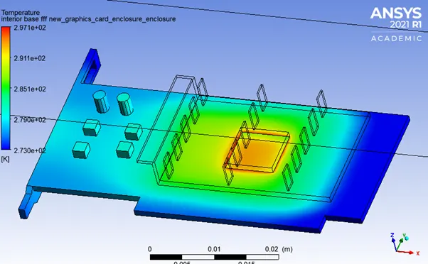
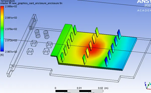
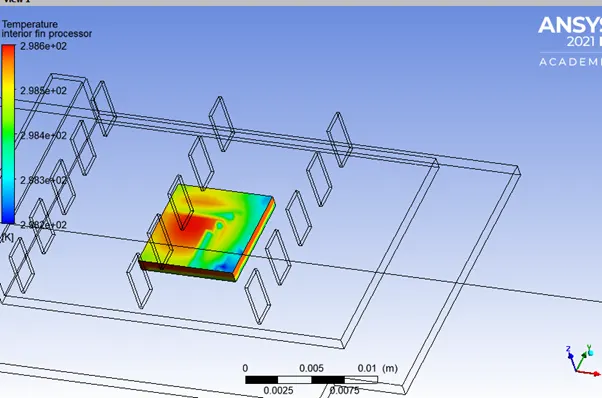
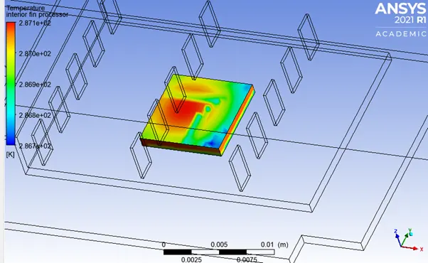
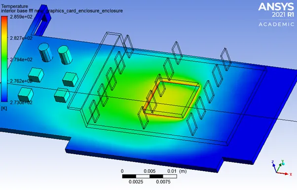
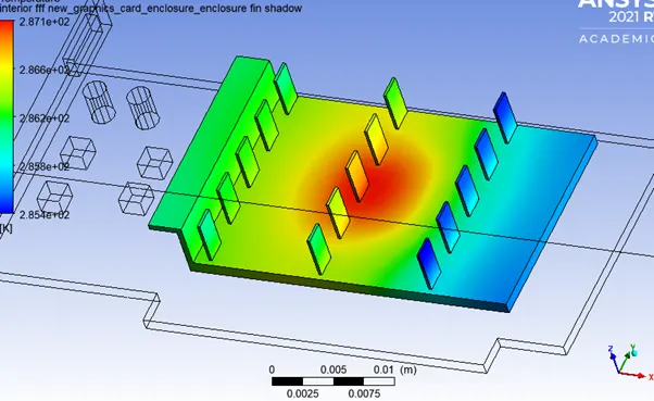
Heat is transferred from processor to fins to atmosphere. That’s why in the middle where processor lies , fin tray seems to have higher temperature than rest of the places. This middle portion is the hotspot (where the processor lies, as it is the heat source).
Velocity-3m/s
Wall-adjacent heat transfer coefficient-434.507W/m2K
Y+ transfer coefficient-244.5w/m2k
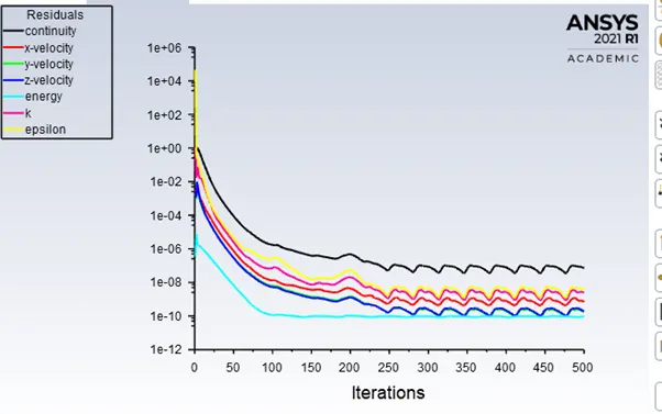
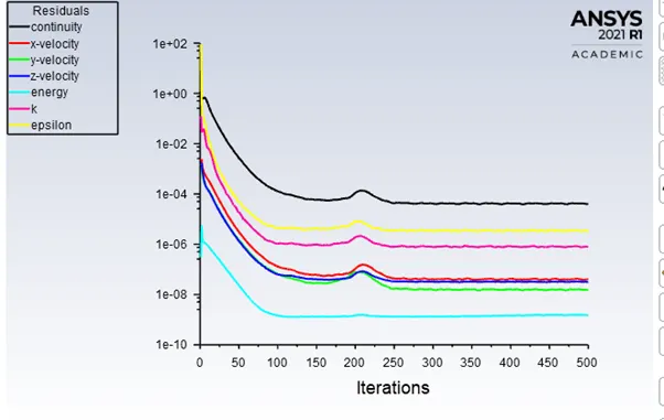
Residual:
After 100 iterations the simulation seems to be converged.
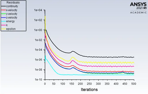
Wall adjacent temperature:
Y plus heat transfer coefficient:
Max temperature-287K
Velocity-5m/s
Wall-adjacent heat transfer coefficient-434.507W/m2K
Y+ transfer coefficient-244.5w/m2k
Residual:
The simulation converges at nearly 100 iterations.
Wall-adjacent temperature curve
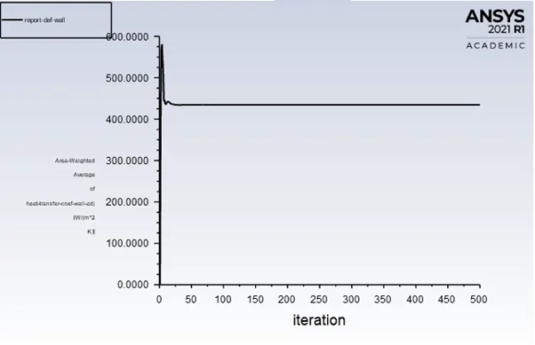
Y-plus transfer coefficient:
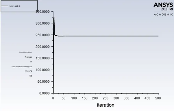
Max temperature achieved-289 K
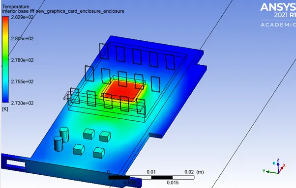
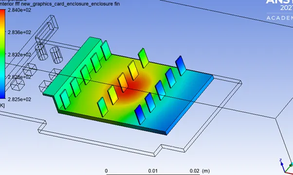
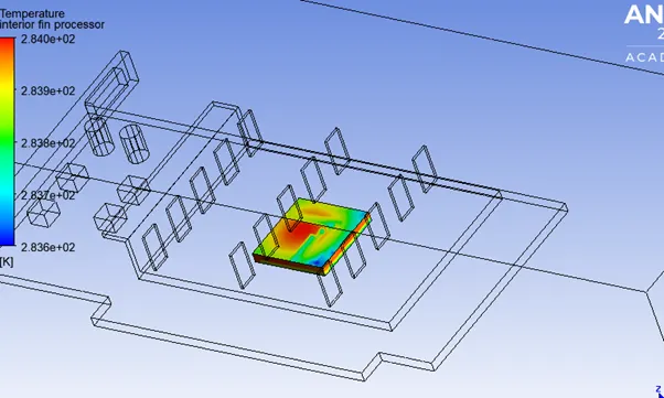
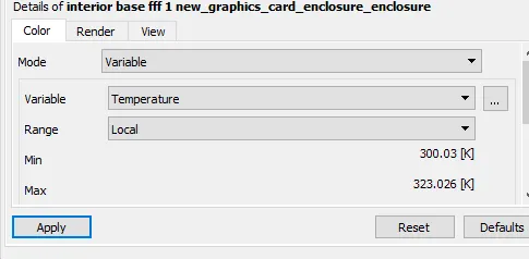
Conclusion: The heat transfer coefficient is in range 400-500w/m2K and the temperature rise in the three cases is not more than 15-20 degree Celsius. The affect of velocity on temperature is nearly negligible for a range of 1-5m/s, the temperature lies between 287K-298K . As velocity increases, cooling increases and temperature rise becomes lesser.