Week 9 - Parametric study on Gate valve.
Parametric study on Gate Valve
Gate Valve is a sluice valve having a gate /disk separating the inlet and outlet and allowing the fluid to flow once disk has been totally opened. This type of valve is very much common in pipe fittings. The mass flow rate of the fluid flowing depends on the lift of the disk. The hand wheel rotates which then rotates the spindle and lifts the disk.
In this simulation, disk is opened for a varying percentage of 20% to 80 % and the mass flow rate is noted. The lift given to disk and mass flow rate has been parameterised .
Geometry:
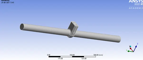
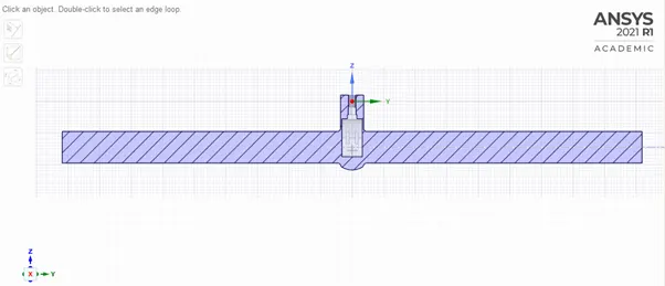
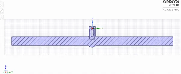
Here the disk needs to be given a lift using the ‘move’ command and then parameterised. The inlet , outlet and bonnet edges should be selected in order to extract the fluid volume. All parts of solid volume should then be suppressed for physics. We can also pull out the extracted inlet and outlet portions for better view in simulation. This can be done using ‘pull’ command in space claim. Whenever we need something to be updated in the fluid volume as per the changes in solid volume, right click on ‘fluid volume’ and select ‘update in context’ option.
Mesh:
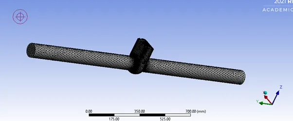
A general mesh of 50 mm mesh size was created and named selection for inlet and outlet is given.
Setup:
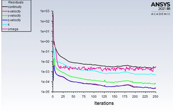
The setup if this study is not complicated. A steady state simulation with pressure-based solver is run. As flow is turbulent, model taken is realizable k-epsilon with scalable wall functions.
Gravity is enabled in the direction opposite to lift of disk i.e., negative z axis as per geometry.
Material -water (change the fluid from air to water in cell zone condition also)
Boundary condition- pressure inlet with 10pa pressure (outlet has 0 pressure).
Standard initialize the solution and compute from inlet.
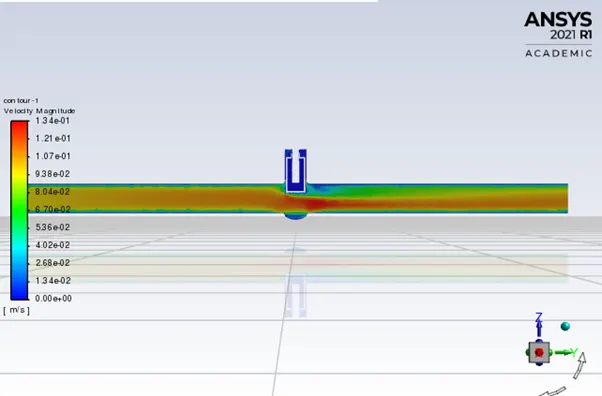
Create necessary velocity contour and mass flow rate report(parameterised) .
Cases as per opening- 10mm, 20mm,30mm,50mm,60mm,80mm
Parameters tab:
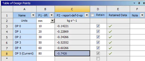
Flow coefficient(Cv)- This tells the relative efficiency of a device allowing the fluid flow. It relates pressure drop occurred due to the valve to the flow rate. Flow coefficient is used in designing of valve and depends valve to valve.
Flow factor or Kv is flow coefficient in metric units. Cv is imperial units defined in Us gallons per minute.
Kv=0.865Cv
Cv= flow coefficient and Kv= flow factor
Formula for flow factor:
SG=Specific gravity of fluid=1 for water
Q=rate of flow (1kg/s =3.6 m3/h)
∆P=pressure drop=10 pa(1 pa=1e-5 bar)
|
S no. |
Lift |
Mass flow rate(kg/s) |
Mass flow rate(m3/h) |
Flow factor(m3/h) |
Flow cofficient(m3/h) |
|
1 |
10 |
0.14221 |
0.511956 |
51.1956 |
59.18566474 |
|
2 |
20 |
0.22869 |
0.823284 |
82.3284 |
95.17734104 |
|
3 |
30 |
0.34266 |
1.233576 |
123.3576 |
142.6099422 |
|
4 |
50 |
0.52552 |
1.891872 |
189.1872 |
218.713526 |
|
5 |
60 |
0.60266 |
2.169576 |
216.9576 |
250.8180347 |
|
6 |
80 |
0.7426 |
2.67336 |
267.336 |
309.0589595 |
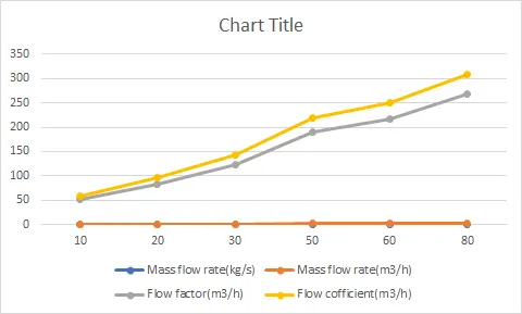
As opening increases, flow coefficient and flow factor increases almost linearly.
Post-processing results:
Geometry-
30mm-
80mm-
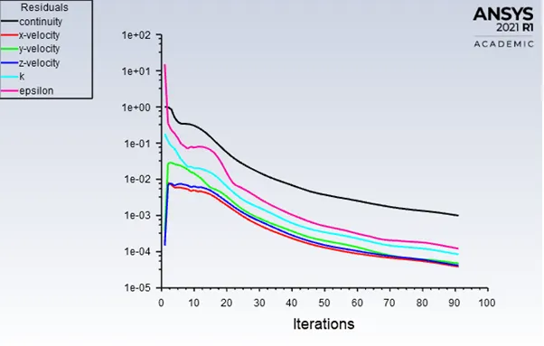
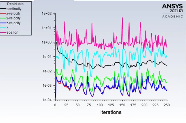
Residual:
20mm-
30mm-
50mm-
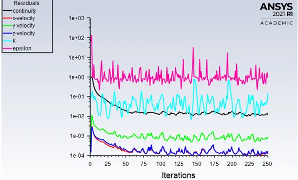
80mm-
Velocity contour-
20mm-
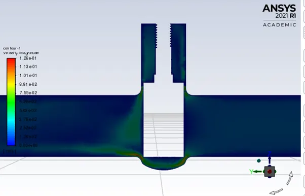
30mm-
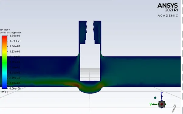
50mm-
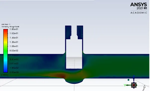
80mm-
Mass flow rate curve-
20mm-
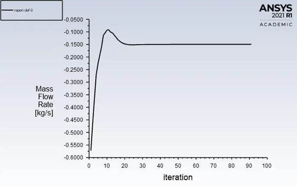
30mm-
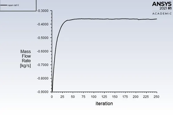
50mm-
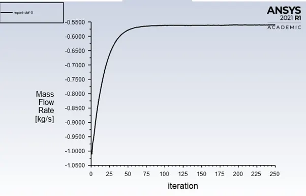
80mm-
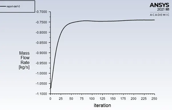
Conclusion- As the opening of disk increases, more mass passes through the valve which increases mass flow rate and flow coefficient.