Week 10 - Simulating Combustion of Natural Gas.
Combustor challenge:
Introduction:
A combustor is a component or area of a gas turbine, ramjet, or scramjet engine where combustion takes place. It is also known as a burner, combustion chamber or flame holder.
Procedure:
Part1:
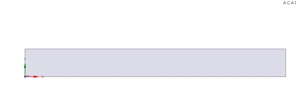
Here we see the reaction of methane and air in a combustor and how the concentration of different products and reactants vary at varying distances from the inlet. In the combustor, there is an inlet for fuel, and other larger inlet for air. Here for the ease of simulation we are using a 2d domain as our geometry.
Geometry:
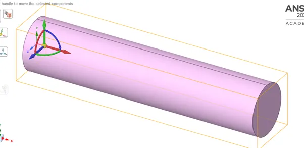
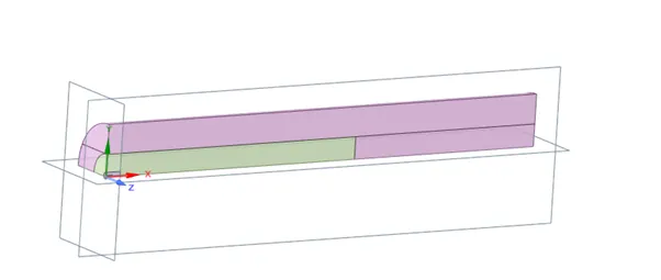
So, basically a combustor here resembles that of a cylinder body and we have to split the body into a single quadrant and then just copy the 2d plane and paste it in a new file. This gives us the 2D domain.
Steps involved in this:
1:
2:
3:Final geometry:
Zoomed view:
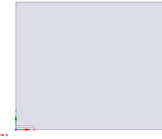
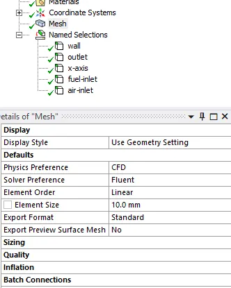
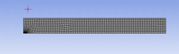
Meshing: Meshing is relatively easy in this simulation. An element size of 10mm seems sufficient and increased sizing near the gap and refine the cells near the slit.
Also, its very important to give correct named selections i.e., separate fuel and air inlet, outlet, wall and the x axis.
Here is the settings screenshot:
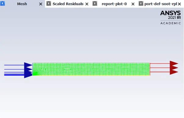
The final mesh looks like:
Setup:
Here we run a steady state simulation because we are interested in the final result, along with a axisymmetric 2d space, pressure based solver.
Model used: k-epsilon , standard with standard wall function.
Species- Use the species transport equations, volumetric type, choose the diffusion at inlet , methane-air model and eddy dissipation.
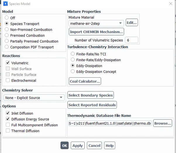
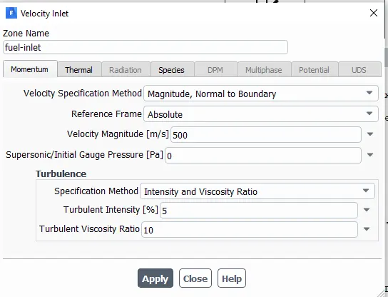
Boundary conditions- Fuel inlet- Velocity 500m/s , temperature-300K, species- ch4 =1 by mole fraction or mass fraction here.
Air inlet -Velocity 0.5m/s, temperature-300K, Species , oxygen=0.23 by mass fraction (n2 is inert and is not considered as a part of the reaction).
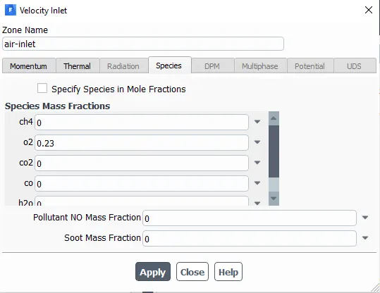
Nox model-on, thermal NOx and prompt NOx for Ch4 i.e methane
Soot model-on, 1-step model, fuel- methane, oxidant-oxygen
Hybrid initialize the solution and create a report definition for soot and NOx.
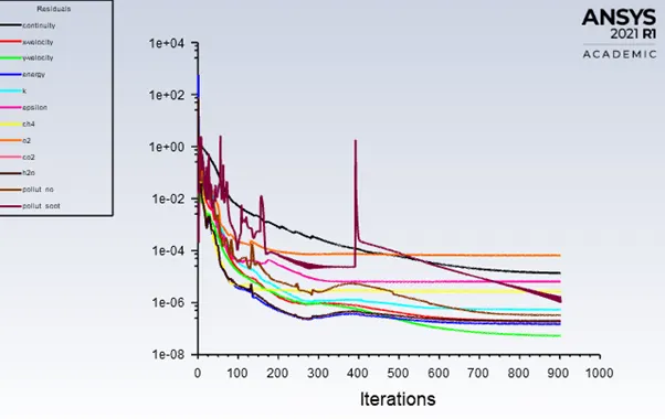
Run the calculation for 1500 iterations.
Post-Processing:
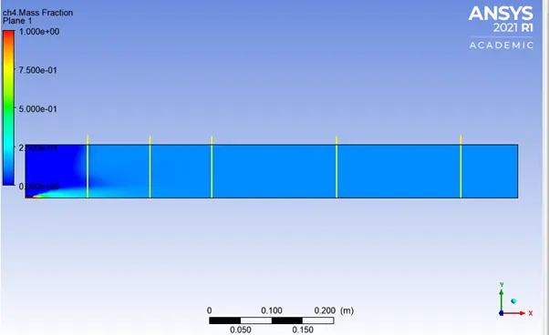
Here, we create 5 lines at different distances to check the concentration to different products and reactants at each of these distances. The plane looks like this:
Also, the plane contour here currently shows the mass fraction of ch4 over the entire domain.
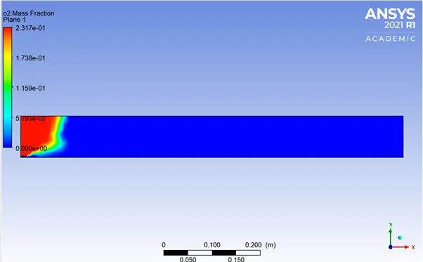
O2 contour:
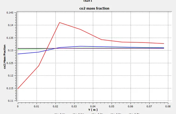
C02 mass fraction for different lines:
The concentration of co2 decreases as the distance from inlet increases. Each line shows variation in the vertical direction .
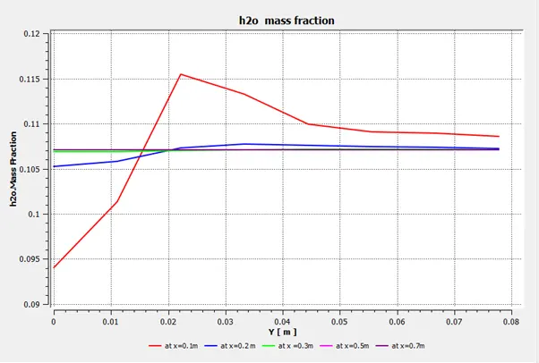
Water mass-fraction for different lines:
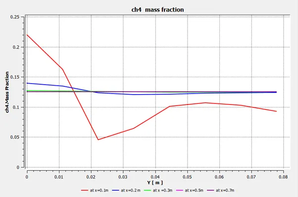
Methane mass fraction:
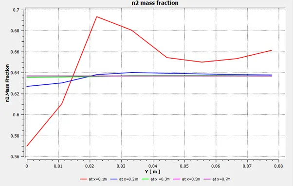
N2 mass fraction:
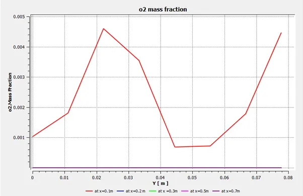
O2 mass fraction:
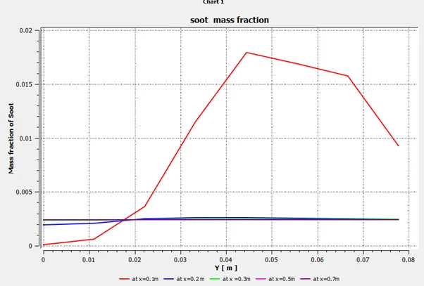
Soot mass fraction:
Soot concentration decreases as the distance from inlet increases. Also the concentration remains same almost at further distances.
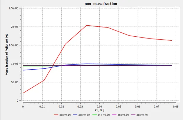
NOx mass fraction:
Part-2 Challenge
Mixing 5 % to 30 % water with fuel by mole.
It means, 0.05 mole fraction of water with 0.95 mole fraction of fuel.
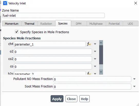
Parameterizing of the fuel and water inlet concentration:
Choose the drop down here to select add new-parameter option.
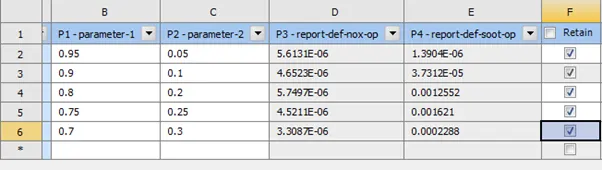
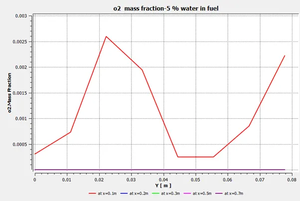
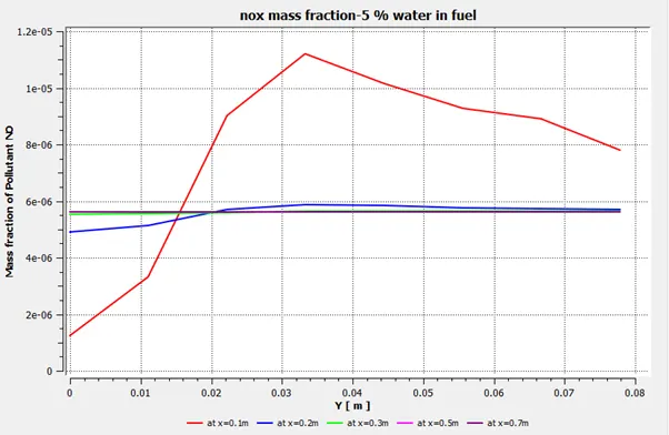
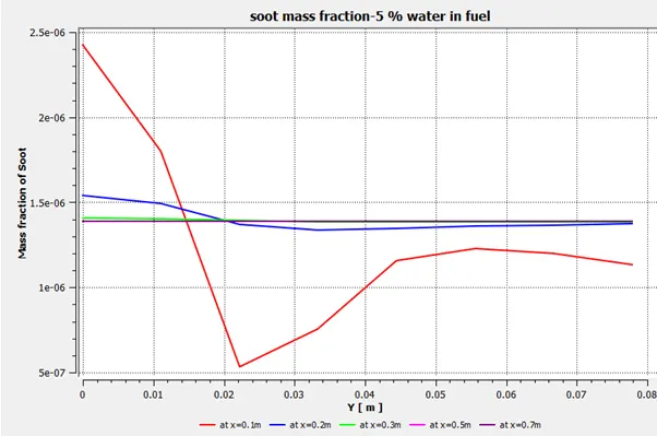
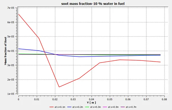
Here we see the effect of mixing water with fuel. NOx goes on decreasing as the water content in fuel is increased (Column D) but soot increases in general (Column E).
Post-processed results:
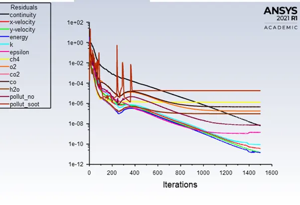
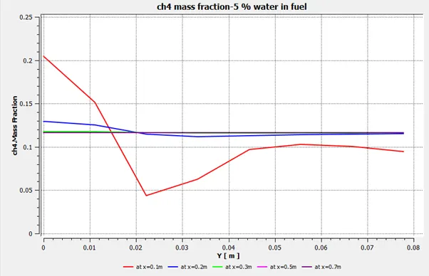
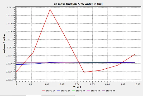
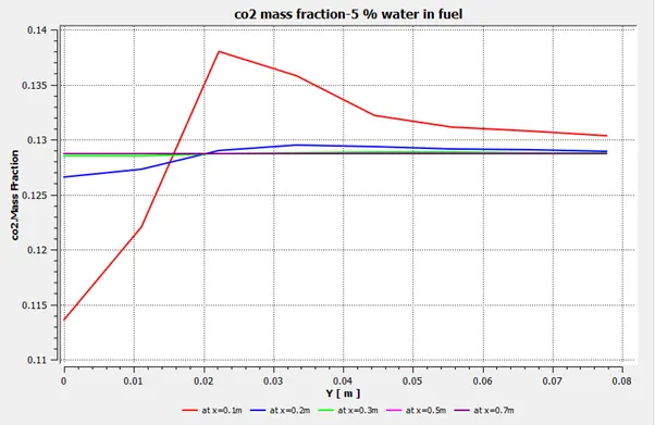
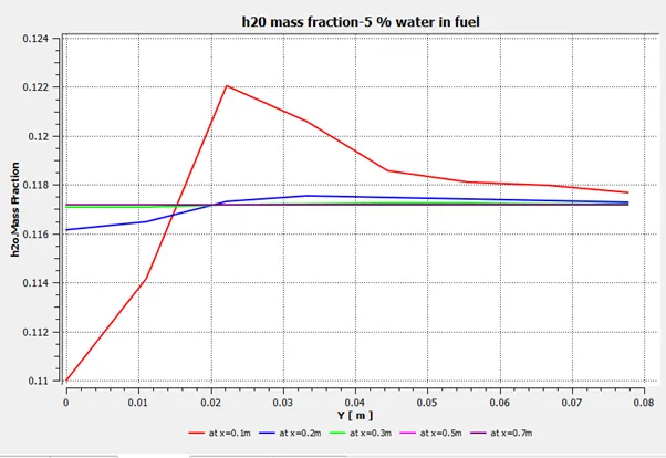
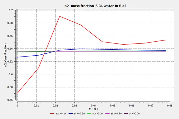
Residual for 5% water with fuel by mole :
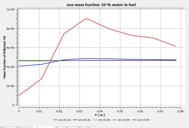
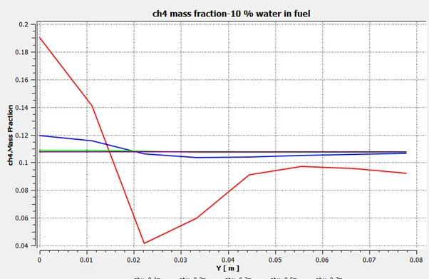
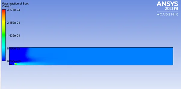
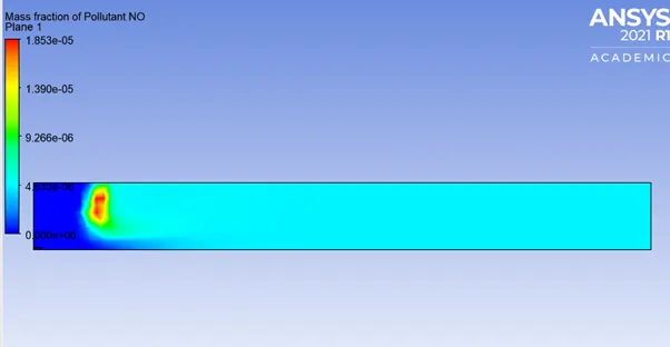
Case2 :For 10 % water by mole
Nox- 4.6522899E-06
Soot-3.7311874E-05
Case3: 20%water by mole
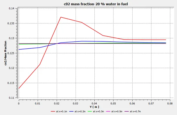
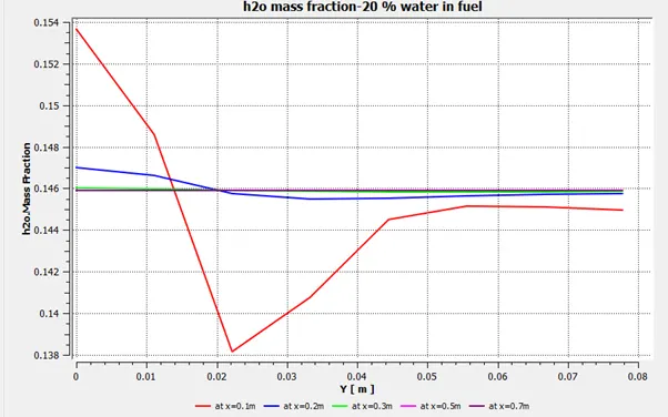
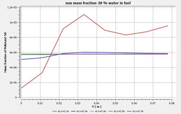
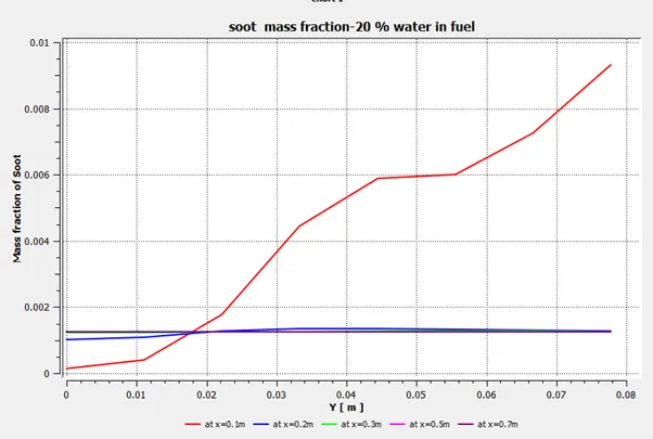
Case4 :25% water by mole
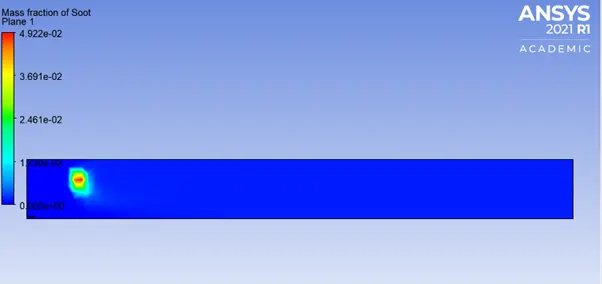
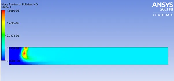
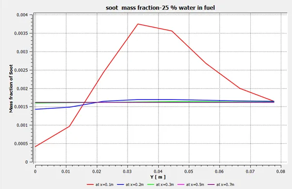
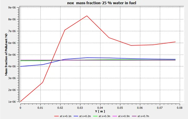
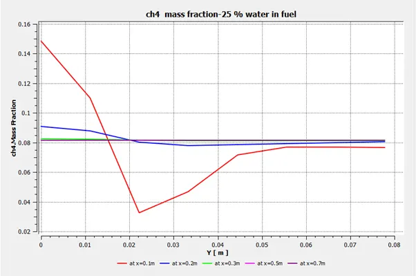
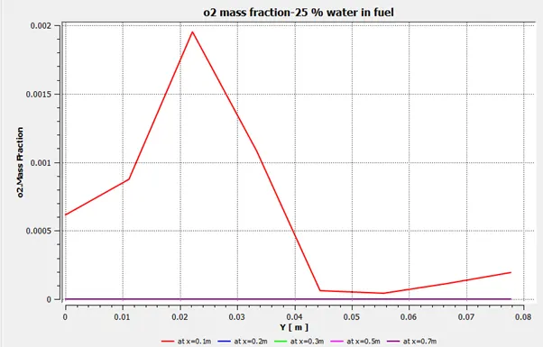
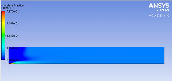
Case5: 30% water by mole
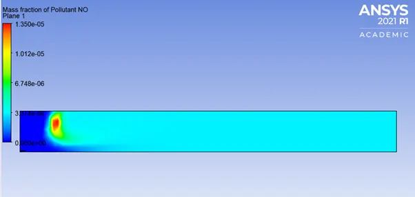
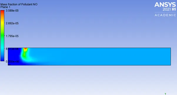
Near the air inlet , NOx concentration becomes higher as compared to other areas.
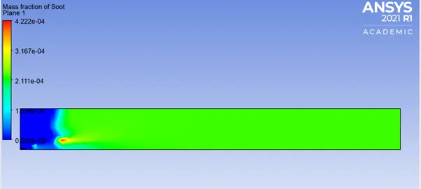
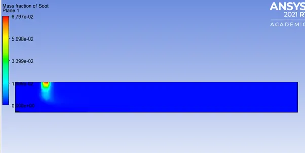
At the middle, soot concentration becomes highest for a small area.
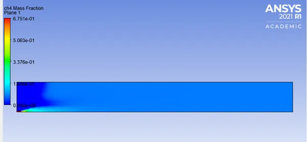
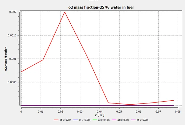
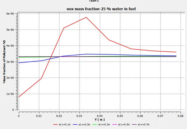
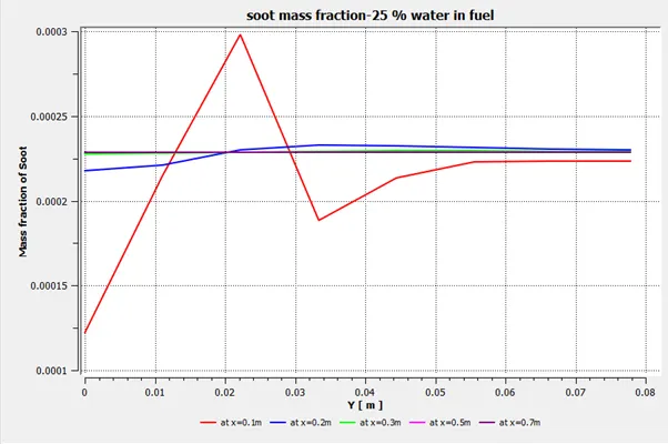
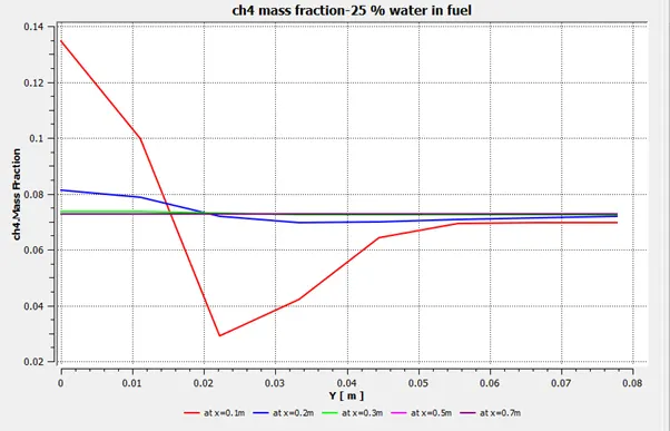
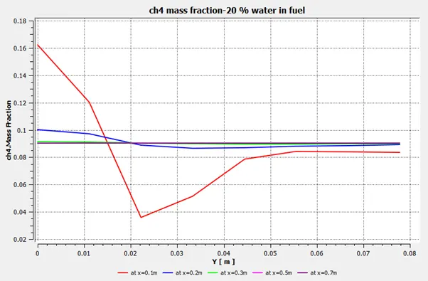
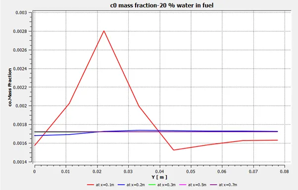
Conclusion: As water is added to fuel, NOx concentration goes to decreasing and soot concentration goes on increasing. Soot and Nox both are undesirable pollutants that come as a product of the reaction and hence we need to have a balanced combination of fuel and water mixture . Also,the mass fractions of reactants and products is more prominent near the inlet as compared to other locations.