Week 10 - Challenge 2- Attachment Feature Creation (Dog House)
DOOR TRIM DOG HOUSE DESIGN:
Aim: To create a Plastic part from a given class A surface of a Door Trim with dog house as per the design rules. Also perform the draft analysis on the created part.
Objectives:
- To create a tooling axis for the component.
- To create Class B & C surfaces form the parameters: Thickness (3mm), minimum draft angle(3°).
- To create a solid body from the closed surfaces formed by joining and trimming Class A, B & C surfaces.
- To perform draft analysis of the final plastic component ensuring the minimum draft angle is met on all the surfaces of the part.
- Create the dog house feature on the proper position as per the design rules, performing draft analysis on the dog house as well.
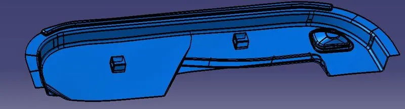
Tool Used: CATIA V5.
Introduction: In this project, a door trim is to be designed using a given class A surface, the parameters for the design are as follows:
- Part thickness: 2.5mm
- Draft angle: 3°
- Design Guidelines of dog house feature is given as:
- Draft - 0.5 degrees on the walls of boss
- Thickness at the base- Typically 40% of the nominal wall thk.
- Height of the dog house feature: 20mm
- Height of the base ‘c’: 3 to 6 mm
- Fillet Radii - 0.25mm maximum radii.
The part is developed keeping the aforementioned parameters in mind while creating class B & C surfaces and subsequently Ribs and screw bosses.
Constraints:
- Changes if any in Class A surface shall be very minimal.
- Part thickness cannot deviate more than 30% of the nominal thickness in any direction.
- All design rules shall be followed strictly.
- All surfaces shall be completely closed before converting to solid. A maximum tolerance of 0.003mm is allowed.
- Minimum draft on rib and screw boss walls is 0.5°.
Report:
- Class A surface:
The following surface is given as the input for the creation of the part. This will be the main aesthetic surface for the switch bezel.
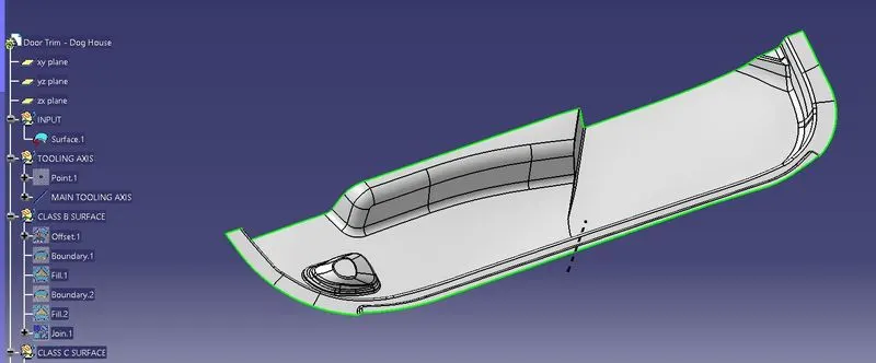
(Class A surface)
- Creation of tooling axis:
- Firstly we visually determine the ideal direction of pull for the simplest geometry of mould, for the given class A surface, the direction of pull should be along the x axis.
- Now, we can create a dummy tooling axis in the y direction using a point on any curve on the class A surface.
- Draft analysis of class A surface:
- To continue with the design process first we need to find out the tooling axis for the surface and check for all the drafts using Draft Analysis tool of CATIA. Use the main tooling axis for the draft analysis. The analysis is done for 3° draft, all the surfaces that have more than 3° draft are highlighted in green.
- It is observed in Class A surface that the minimum draft angle of 3° is satisfied for the whole part.
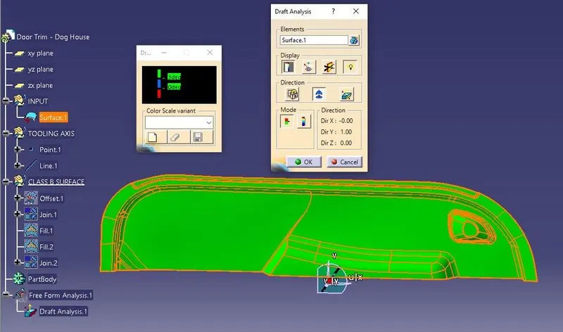
(Class A Draft analysis using main tooling axis with 3° draft)
- Creation of class B surface:
- Class B surface is created by offsetting the main surfaces of the class A surface.
- After creating the offset, there are missing fillet patches. These patches needs to be corrected for proper class B surface.
- Using fill and join tools, class B surface is created.
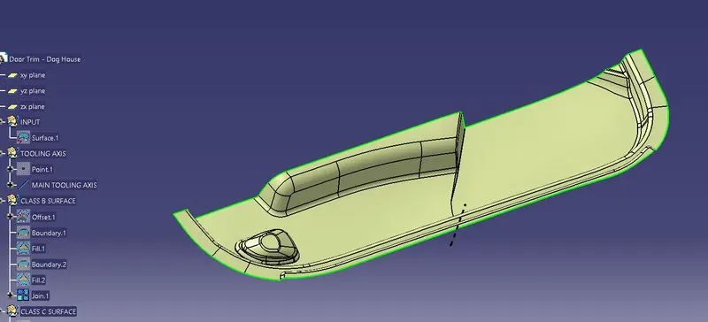
(Class B Surface creation using offset of class A, Missing Patch corrected with fill surface command)
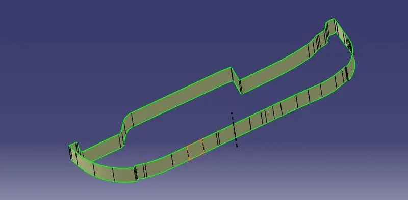
- Creation of class C surface:
- Class C surface is created by extracting the boundaries of class A surface and using the sweep command perpendicular to the class A surface.
(Creation Of C Surface)
- Creation of a close surface:
- Join the Class A and C surfaces; Make sure that there are no open boundaries.
- After getting a seamless join/ trim of class A & C surface, check the intersection of Class A+C surface with the Class B surface, extrapolate the Class B surface accordingly wherever needed to cut the A+C surface
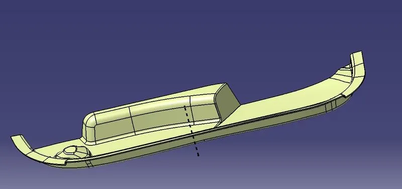
(final closed surface using class A, B & C surface)
- Creation of part using the surface:
Using the close surface feature, make the part out of the created surface.
- Draft analysis of Part:
Using the tooling axis and similar method to previous, analyse the part for draft angles in all surfaces. Make small changes in angle of draft and angle of pull until all surfaces are shown to have proper minimum values of draft.
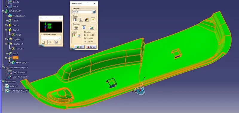
(final draft analysis of the part)
- Creation of Dog House:
- Making a sketch on the flat surface of the body, position the line where the dog house is desired.
- Extrude the sketch to make a surface, thicken the surface making sure that it intersects the main body.
- Using the copy and translate tool, make the dog house at other locations.
- Using Boolean operation, union trim the bodies into a single body to create a part.
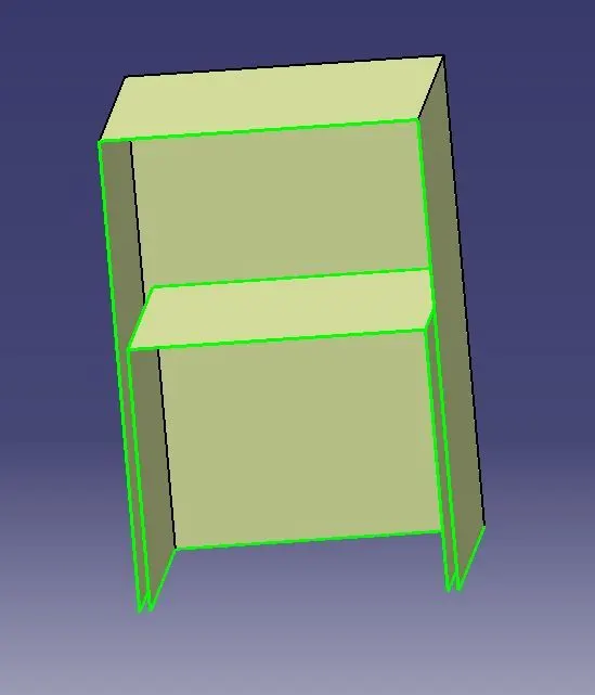
(SURFACES FOR DOG HOUSE CREATION)
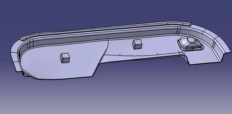
(final part with dog house)
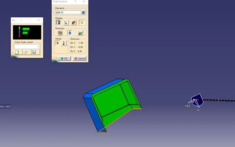
(dog house draft analysis)
Conclusion:
- The solid part is obtained using the close A, B & C surfaces. The draft analysis shows the part has proper minimum value of draft on surfaces that had proper class A surface and acceptable draft value where input had less than minimum draft angle. This ensures that the surface finish of the plastic component will be smooth when manufactured with the mentioned draft angle and tooling axis.
- Dog House features are created ensuring proper assembly of part.
- Dog House features are created as per design guidelines and follow the design rules.