Roof Design
CAR ROOF DESIGN
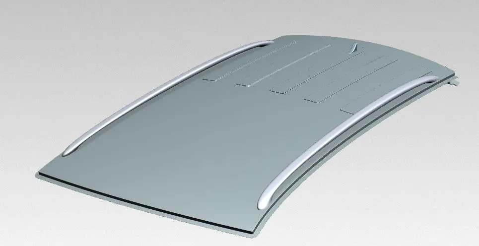
Roof is the top BIW component of the car. It protects the passengers from the weather (sun, rain, wind). It also protects the passenger in case of vehicle roll over or crash.
AIM
The aim of this study is to design the roof assembly along with the roof reinforcement and optimize the position of bow roof rails and middle roof rail by doing curvature study, heat distortion study and snow load study.
OBJECTIVE
- <!--[endif]-->Create Roof Outer Panel flanges using the Class-A surface.
- Create Front and rear roof rails using the master sections and Class-A Surfaces.
- Create Bow Roof Rails and center roof rail using master section.
- Perform the curvature study, heat distortion study and snow load criteria study.
- Optimize the position of the rails if required.
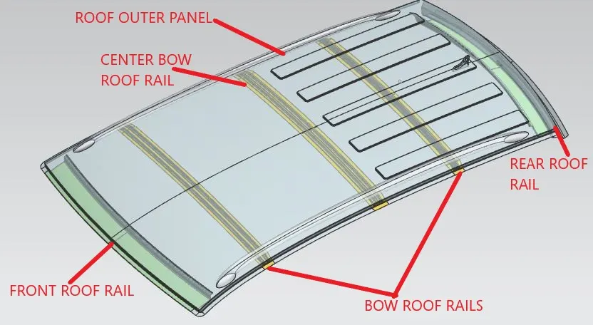
DESIGN OF CAR ROOF
The Styling surface of the car roof given, the design of the roof has to be done using this surface.
Design of Roof Outer Panel
- Clean Up the Class-A Surface by extracting and trimming the sheet.
- Using the master Section, make the front, side and rear flanges. Make sure the draft angle must be more than 7°. The first flange in the rear side of the roof has less than 7° of draft. This flange will be made in a different operation than the front and side flanges.
- Join the front and side flanges using the through curve mesh.
- Using bridge curve, cut the rear and side flange for no overlap.
- Apply appropriate fillets.
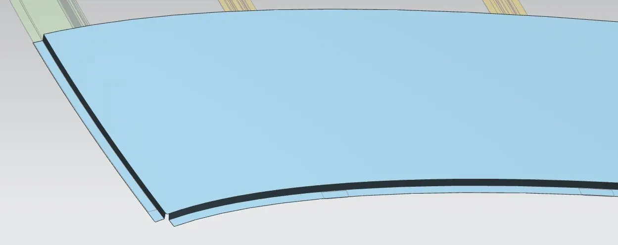
(Roof Outer Flanges)
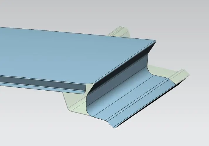
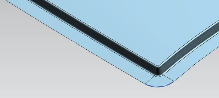
(Flanges as per master section)
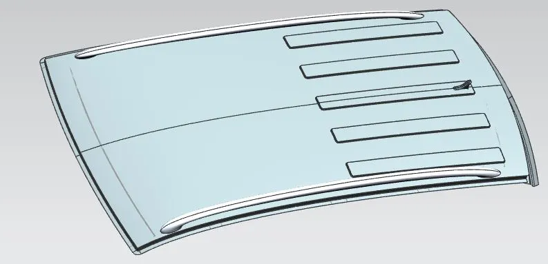
(Roof Rail Final after adding embosses)
Design of Front Roof Rail
The front roof rail can be designed using the master section.
- Offset the top face and the front flange of the roof outer to required dimensions.
- Following the master section, make the front roof rail keeping in mind that the offset is given as: The Roof outer will be thickened inwards and the front roof rail will be thickened upwards. Therefore the offset must be provided in such a way that there is no overlap between the front roof rail and the roof outer.
- Front flanges of the roof and the front roof rail are spot welded together, therefore there is no gap between the flanges.
- Provide the appropriate fillet to the edges.
- Using the Datum plane, make an offset plane at a distance of about 540mm, Use this plane to trim the front roof rail to the distance of the required front roof rail. This is done as the front roof rail will not span the entire width of the car roof, it will stop to provide clearance for joining with the body panels.
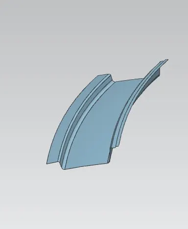
(Front roof rail as per master section)
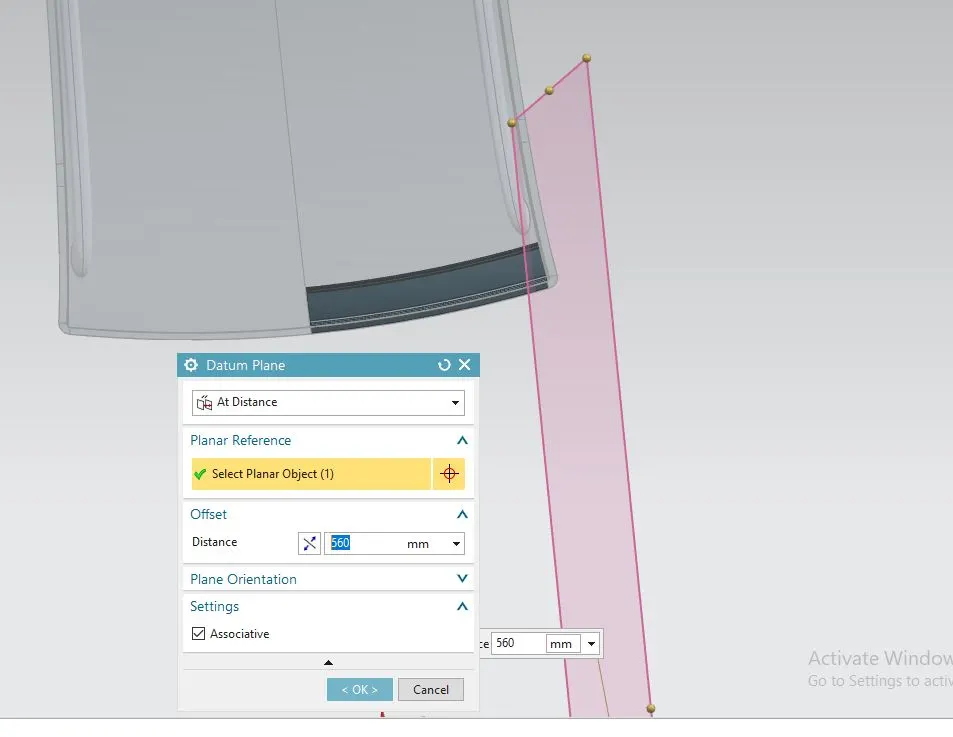
(Front roof rail need to be cut for A-Pillar and roof mountings)
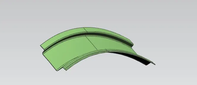
(Roof Rail Front)
Design of Rear Roof Rail
- Similar to the front roof rail, use the master section along with the offsets of the outer roof surface to create the rear roof rail.
- Provide the clearance for the mastics as required in the master section.
- Apply the appropriate fillets.
- Similar to the front roof rail, use an offset datum plane to cut the rear roof rail surface to satisfactory width.
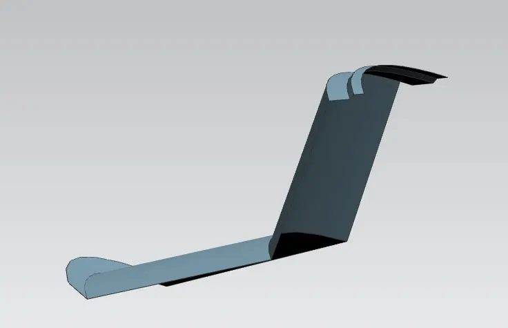
(Rear Roof Rail Flanges as per master section)
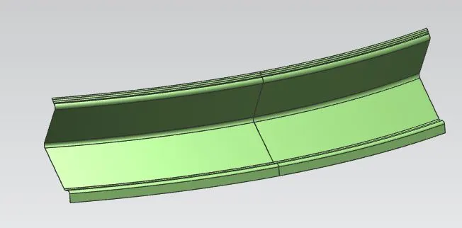
(Rear Roof Rail)
Design of Bow Roof Rails
- The Bow roof rails are created using the master section and the offset from the hood outer.
- Create an ‘on curve’ datum plane on the center edge of the roof outer. For now, use an arbitrary value for the arc length, keeping in mind that the front bow roof rail must be placed around the front third of the roof.
- Using the master section and offset face, create the flanges of the bow roof rail.
- Using a datum plane, cut the bow roof rail to about 540mm, this is done to make way for the surface that will transition the flanges to a straight surface parallel with roof to be spot welded with the roof flange.
- Cut the side flange of the roof to match the bow roof rail, offset the side flange to 2x thickness of sheet metal.
- Use the studio surface or through curve mesh command to make a swept surface that connects the flanges to the straight surface.
- Us this method to create a second bow roof rail in the rear third of the roof.
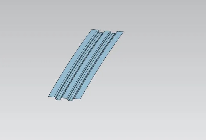
(Bow roof flanges as per the master section)
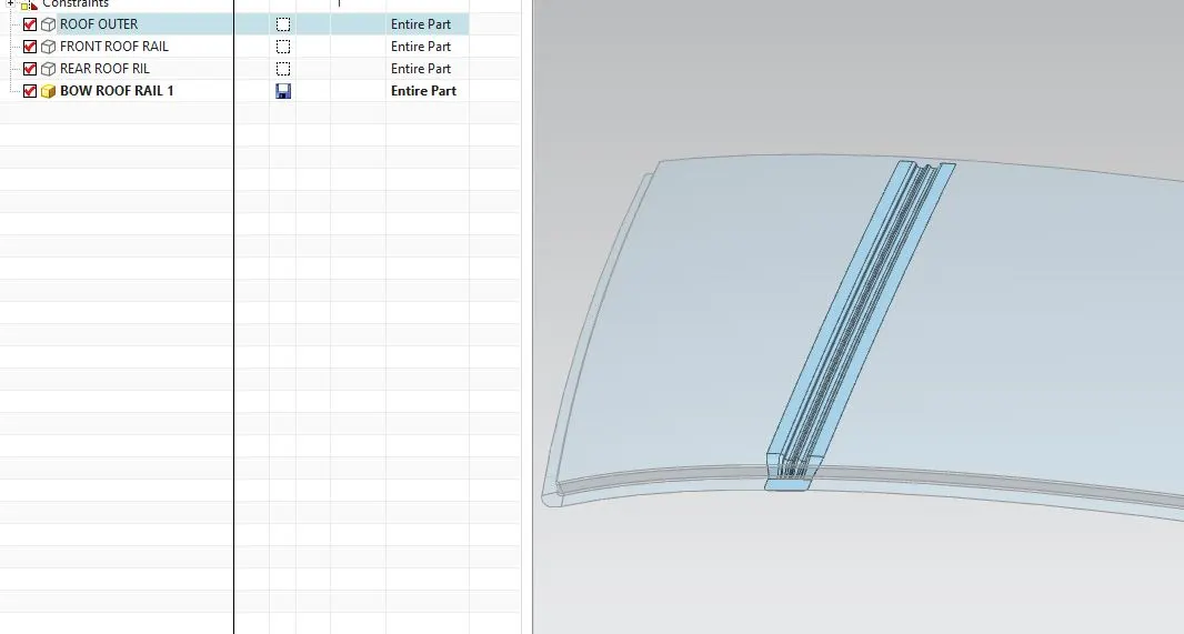
(Bow Roof Rail Front)
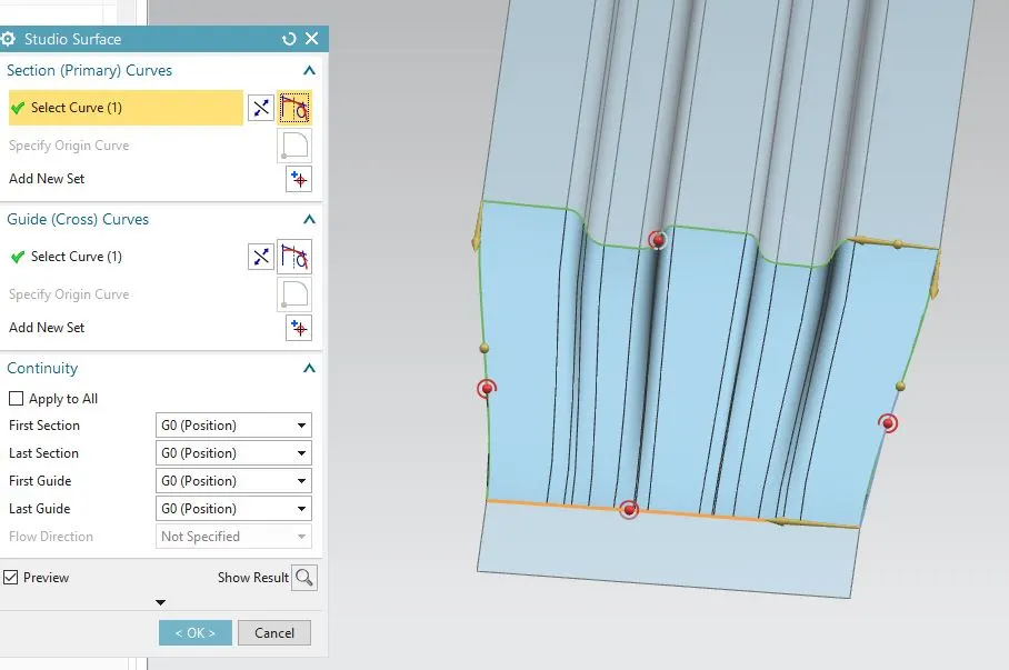
(Sweeping flanges to merge with the roof ditch to be spot welded.)
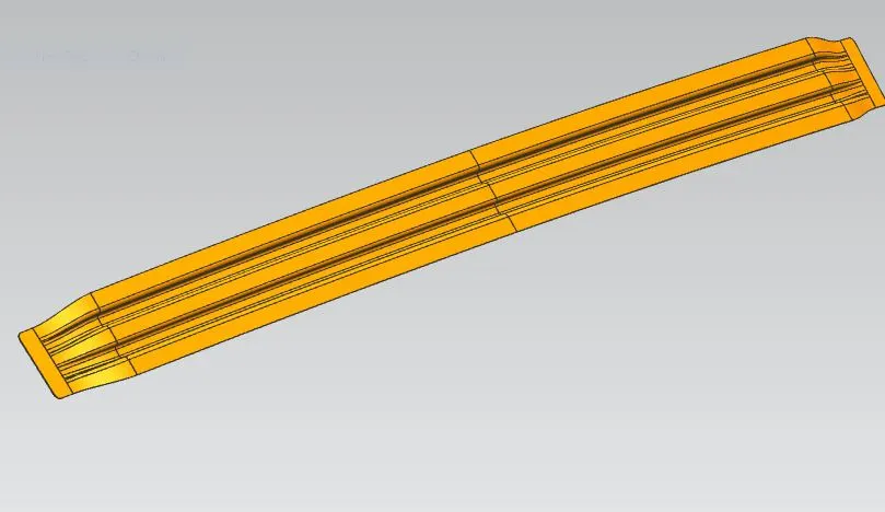
(Bow Roof Rail)
- Design of Center Roof Rails
- The center roof rail is created similar to the bow roof rails. Using the master section and the offset surface.
- The center roof rail needs to be reinforced with yet another flange in case there is a sunroof.
- For this study, we do not require to add this extra reinforcement as there is no sunroof in our design.
After the creation of all the components, mirror all the components individually and then sew the surfaces. If there are any gaps/intersections in the output surface, extend edge before mirroring and sewing.
Thicken all the individual components for 0.75mm sheet metal thickness.
The part design for the roof is ready
After completing the design the roof assembly, calculations for the heat distortion criteria and the snow loading condition needs to be done to ensure the strength of the roof and the reinforrcements and the placement of the bow roof rails.
HEAT DISTORTION CRITERIA
Heat distortion temperature is the temperature at which the sheet metal softens and deforms under specific load conditions.
This study is done to check if the roof can withstand the temperature with respect to the positioning of the reinforcements.
As the outer panel of the roof heats up, it deforms, the deformation is high due to the fact that the metl sheet used to form the outer panel of the roof is very thin; usually about 0.75mm thick. The sheet metal needs to be thin to reduce the total weight of the car, hence we need to deploy measures to ensure that there is no deformation in the car's roof in high temperture while keeping the weightminimum.
The reinforcement in the form of the bow roof rails when place in specific positions can provide the structural support and also stregth against the bending/deforming under high tempertures.
The formula for testing the acceptability in case of thermal distortion study is given by:
W = [1.73 x 10^(-3) x L] + [1.85 x 10^(-8) x (R^2)/t] + [1.10x10^(-3) x l] - 2.68
Were,
L = Roof Length in X-Direction[mm](Roof dimension in 0-Y)
R = Roof curvature
R = 2(Rx*Ry)/(Rx+Ry)
Rx = X curvature
Ry = Y curvature
t = Roof plate thickness [mm]
l = Bow Roof Span [mm]
The Acceptance criteria for this to qualify the design requirement is W<2>
We can perform the calculationusing excel and get the following results:
| HEAT DISTORTION CALCULATION | ||||||||||
| ROOF LENGTH(L): | 2082 | A=1.73 x 10^(-3) x L | B=1.85 x 10^(-8) x (R^2)/t | C= 1.10x10^(-3) x l | W=A+B+C-2.68 | ACCEPTANCE CRITERIA | ||||
| BOW ROOF SPAN(I) | RX | RY | R=2(RX*RY)/(RX+RY) | W< 2> | ||||||
| CASE 1(I) | FRONT-BOW ROOF 1 | 295 | 5736 | 2264 | 3246.576 | 3.602 | 0.260 | 0.3245 | 1.506 | OK |
| CASE 2(I) | BOW ROOF 1- CENTER BOW | 529 | 5083 | 5749 | 5395.526 | 3.602 | 0.718 | 0.5819 | 2.222 | OK |
| CASE 3(I) | CENTER-BOW ROOF 2 | 340 | 4019 | 10369 | 5792.745 | 3.602 | 0.828 | 0.374 | 2.124 | OK |
| CASE 4(I) | BOW ROOF 2-REAR | 428 | 3323 | 14306 | 5393.254 | 3.602 | 0.717 | 0.4708 | 2.110 | OK |
Therefore the design qualifies the test; thermal distortion criteria passed.
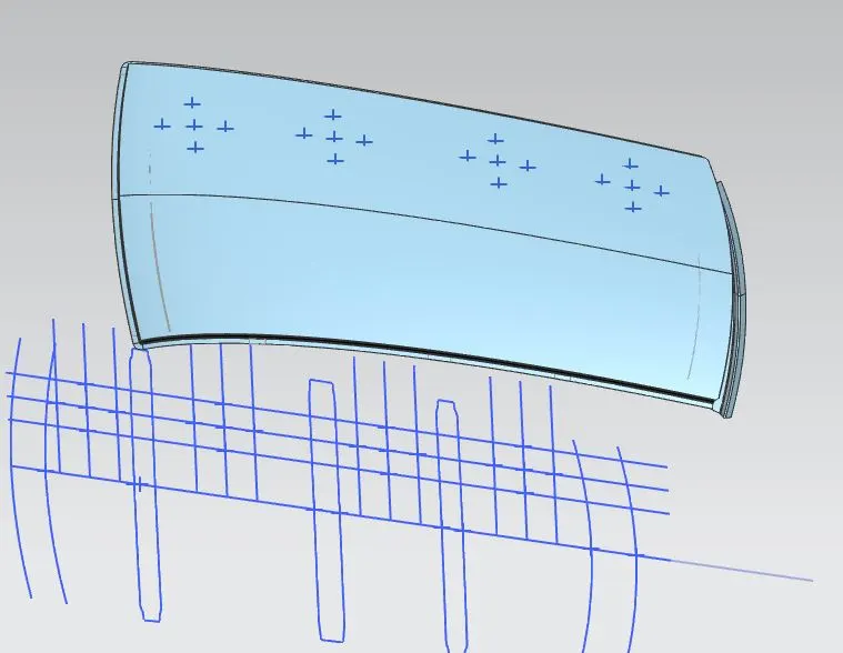
(Curves Projected for heat distrtion study)
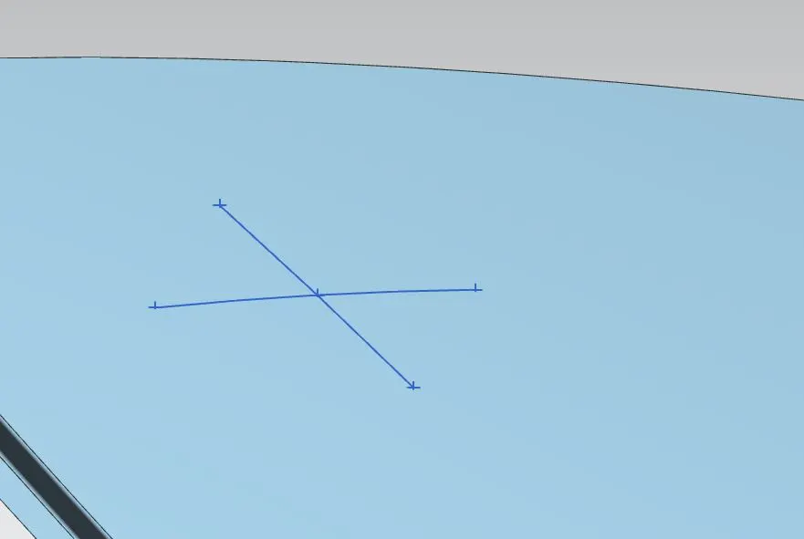
(Arcs made from projected curves for Rx & Ry for heat istrtion calculation)
SNOW LOADING CONDITION
The test for the snow loading condiion is done to ensure the strength of the roof under loading condition. This is done to check if the vehile can endure the load of snow without any permanent deformation in cold climates.
Similar to the heat distortion criteria study, the position of the bow roof rails and the thickness and geometry of the roof will affect the study.
Flatter parts of the roof without reinforcement when cubjected to loading condition may undergo permaent defromation, to reduce this, we can reinforce he roof in the flatter parts, increase the thickness of the sheet metal, alter the curature of the roof or provide embosses to the roof to inrease the strength of the roof.
The formula for testing the acceptability in case of snow loading criteria study is given by:
Qr = [Iy x t2] / [α x s x [(Rx + Ry)/2]2 x 10-8]
Where
α = My x Lx2 x 10-12 , My = Y(Ly-Y)
Acceptance Criteria = Qr ≥ 3.1
t = Roof plate thickness [mm]
Ly = Distance between the front and rear roof Rails on the Vehicle along with 0Y[mm]
Length of Roof panel with the center point between Roof rail Front /Rear as the front and rear reference point.
Lx = Distance between the Left and Right end of the roof on the Roof BOW [mm]
Width of the roof panel exposed on the surface.
Y = Distance front Front Roof Rail to Roof BOW[mm]
s = Distance for which Roof BOW bears divided load [mm]
s = L1/2 + L2/2
Iy = Geometrical moment of inertia of Roof BOW (Y cross-section )[mm4]
Rx = Lateral direction curvature radius of roof panel Y cross-section on Roof BOW [mm]
Roof panel curvature Radius of the Length Lx in Front view
Ry = Longitudinal Direction curvature radius of the Roof panel X cross-section on Roof BOW [mm]
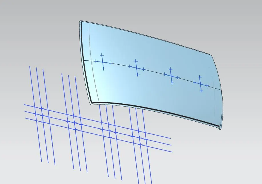
(Ars created with projected points for snow load criteria study)
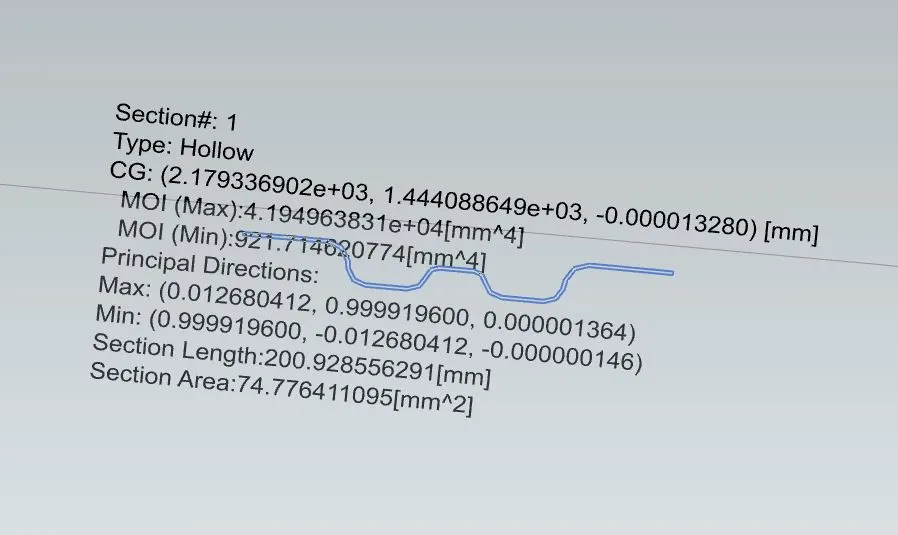
(Section moment of inertia calculton for cnter roof rail)
The calculation is done as:
| SNOW LOAD CRITERIA CALCULATION | ||||||||||||||
| ROOF LENGTH(L): | 2082 | Qr = [Iy x t^2] / [α x s x [(Rx + Ry)/2]^2 x 10-8] | ACCEPTANCE CITERIA | |||||||||||
| MOI(min)(mm4) | Y | MY=Y(LY-Y) | LX | α=My x Lx^2 x 10^(-12) | L1 | L2 | S=(L1+L2)/2 | RX | RY | R=(RX+RY)/2 | Qr = [Iy x t2] / [α x s x [(Rx + Ry)/2]2 x 10-8] | Qr>3.1 | ||
| CASE 1(I) | BOW ROOF 1 | 278.9 | 388 | 605668 | 1153 | 0.80518049 | 388 | 606 | 497 | 4719 | 2349 | 3534.000 | 3.139 | OK |
| CASE 2(I) | CENTER BOW | 921.7 | 994 | 949270 | 1101 | 1.150706043 | 606 | 417 | 511.5 | 3756 | 5858 | 4807.000 | 3.812 | OK |
| CASE 3(I) | BOW ROOF 2 | 746 | 1411 | 759118 | 1066 | 0.862628294 | 417 | 537 | 477 | 4255 | 10821 | 7538.000 | 1.795 | NOT ACCEPTABLE |
| CASE 4(I) | CENTER POINT | 1949 | 0 | 1051 | 0 | 537 | 537 | 537 | 4071 | 16000 | 10035.500 | NOT REQUIRED | ||
| NOTE: FOR THE BOW ROOF 2 CONDITION, THE R VALUE TO TOO HIGH, ie THE ROOF IS TOO FLAT. CHANGING THE GEOMETRY OF FLANGE TO INCREASE MOI WILL NOT HELP MUCH, ALSO, MAKING MULTIPLE ROOF RAIL WILL INCREASE THE WEIGHT, HENCE WE CAN INTRODUCE EMBOSSES IN THE OUTER PANEL TO COUNTER THIS. | ||||||||||||||
Therefore, the design of the roof qualifies for all sections except from the center bow roof rail to the bow roof rail 2.
To inrease the strengt of our roof, we can add emboss in the rear section of the roof. Thsi will greatly increase the strength of the roof for the snow load criteria condition. Adding extra longitudional reinforcements like exterior roof rail will also help in increasing the strength of the roof.
Emboss is added in the roofs of many passanger cars for the reason of increasing the strength of the roof, usually it is only in the rear side of the roof as the rear is generally more flat than the front.
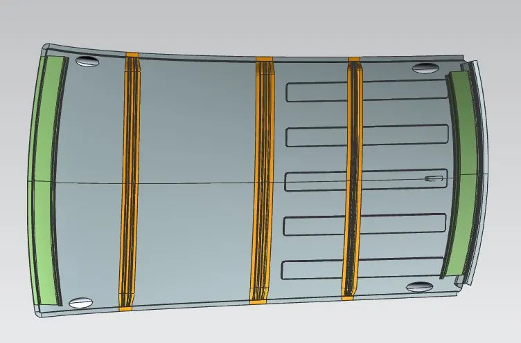
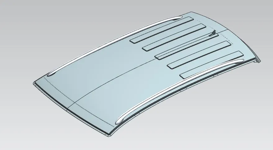
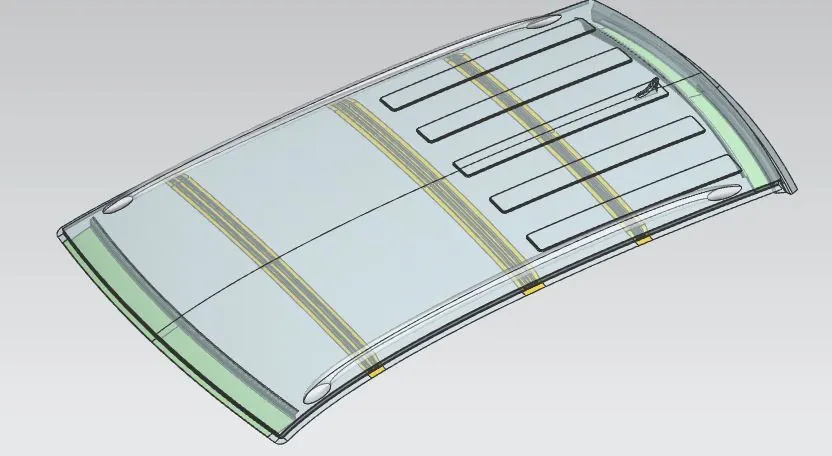
After adding the emboss, the strength of the roof is greatly increased, hence it can withstand snow loading condition.