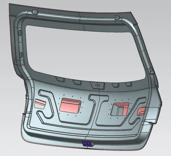
Design of backdoor
DESIGN OF THE BACK DOOR OF A CAR
Back Door is the rear BIW closure component of a car. Back door or the tail gate is considered the fifth or the third door of the car. It can swing vertically like in hatchbacks or sideways like in SUVs and minivans. The term Tail gate is generally used for the closure component of trunk for sedans and coupes.
AIM
The aim of this report is to demonstrate the particulars of designing a back door using Class-A styling surface. Design all the components for the back door module. Elaborate the design considerations of each component of the back door assembly and perform the draft analysis for each of the components to validate the manufacturing process.
DESIGN TOOL USED: SIEMENS NX
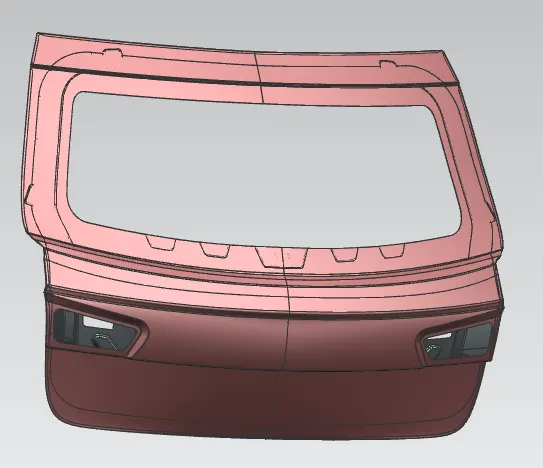
GIVEN DATA: The Class-A styling surface of the car is given. The back door is divided into 2 panels: Back Door Upper and Back Door Lower.
 (Class A styling surface)
INTRODUCTION
The design of the back door begins with the Styling surface received from the styling team. We need to make the engineering drawings from these Class-A surfaces. The changes done to the styling surface must be minimum if at all necessary.
For the back door assembly, we need to prepare the models for the
- Back Door Outer (Upper and Lower).
- Back Door Inner Panel (Single panel for aluminum MOC).
- Hinge Reinforcements.
- Gas Stay reinforcements.
- Wiper reinforcement.
- Latch and Striker Reinforcement.
BACK DOOR OUTER PANELS DESIGN
The back door panels are manufactured using the metal punching process. The sheet metal is first punch-formed in the shape of the outer panels and then hemming is done to assemble the outer and inner panels together.
The design of the back door outer panels start with the cleanup of the Class-A surface. The Surface needs to be blended properly so that it will not affect the thickening of the panel.
The upper and lower back door outer panels are joined individually. The upper and the lower panels needs to be spot welded together later so a flange length of minimum 8 mm is required for that operation. Ensure the creation of each flange. After extracting the upper and lower panels and copying them to new components we can start the top down approach to design the back door assembly.
<!--[endif]-->
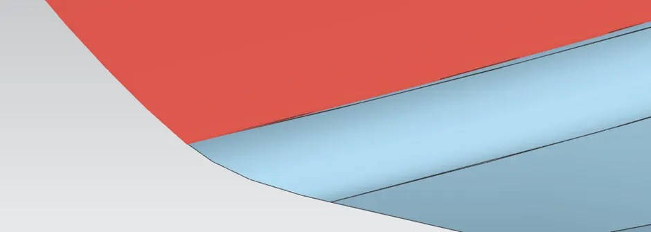
(The surface needs to be corrected as the curves converge on a point, this will create problem while sewing the surface and also when adding thickness to the part.)
DESIGN OF BACK DOOR UPPER & LOWER PANEL
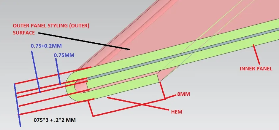
Post cleanup of the styling surface the hemming in the outer panel needs to be designed. For this, an offset of the final outer surface (post cleanup) is used. The offset dimension is determined by the thickness of the sheet metal and the gap required for the hemming glue. For this instant, the sheet metal thickness is 0.75mm and the gap for hemming glue is 0.2mm.
<!--[endif]-->
The class-A surface is offset and then trimmed to 8mm offset curve in face. The average length of the hem is about 6-8mm. Relief for the corners is given. The minimum length /overlap of the hem should not be below 3 mm. this should be taken into consideration while providing the relief in the corners.
A flange perpendicular to both class-A surface and also the offset surface is created using law extension. To make sure that the flange cuts the offset surface, an angle of 7-10° can be given while creating the law extension.
Using the three face blend with the class-A, the offset surface and the law extension, a smooth blend can be created for the hem. Before that many correction need to be done to the class-A, the offset and the law extension. The quality of the styling surface determines the creation of the hem. Therefore cleanup of surface is most important. Correction and checking for the feasibility of 3 face blend is done until the correct desired blend is achieved.
The surface is mirrored and thickened. The thickness of the sheet metal for the outer panel is 0.75mm. The thickening is done inwards.
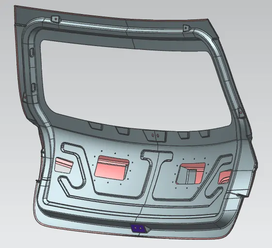
DESIGN OF BACK INNER PANEL
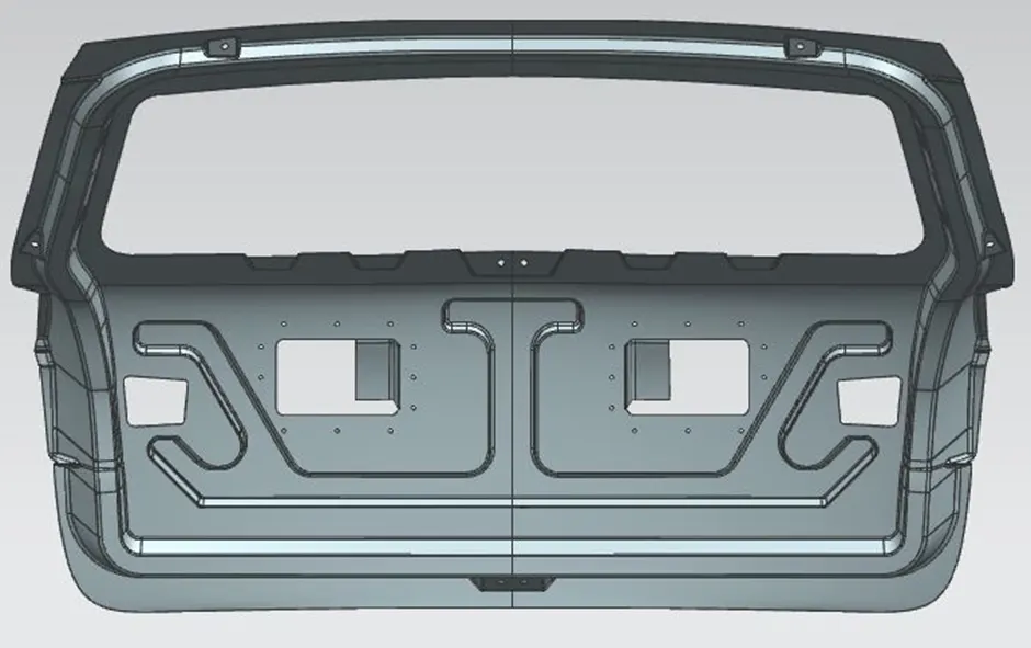
The back door inner panel is manufactured using deep drawing process. In the deep drawing process, the sheet metal is radially drawn into the die cavity by the mechanical action of a punch. In this process the workpiece is put onto the die and the blank-holder is then introduced on the top of the workpiece, which is not deformed by the punch.
<!--[endif]-->
<!--[endif]-->
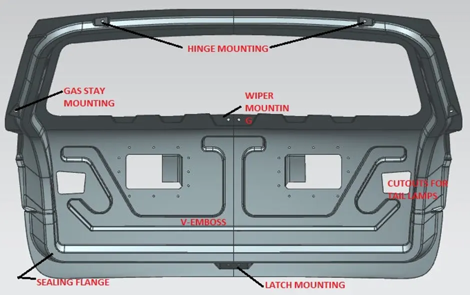
(Various features of the inner panel)
The inner panel can be manufactured using both steel and aluminum. Steel panels are generally heavier than aluminum panels even though the sheet metal thickness of Al is more than twice of that of steel. Still It is cheaper to produce steel panels. In this case, steel is considered as the material of construction.
The design for inner panel is done by extracting the class-A surface of both outer upper and lower panels and offsetting the surface by (0.75*2+.2) fro the position of inner panel flanges.
The sealing flange is then designed. The sealing flange is the area over which the sealing rubber sits. This stops water or dirt from entering the cabin of the car. All swinging component connected to the cabin of the car have sealing flanges. It is present is doors as well. Generally the width of the sealing flange is at least 25mm.
Sealing flange is created using offset and law extension command.
Creation of V-Emboss: After sealing flange and joining the inner panel, v emboss is created in the inner panel. The emboss is towards the outer panel. This is done so that the emboss can dissipate some force during rear collision condition.
Creation for cutouts for tail lamps are then prepared. During the assembly and replacement/repair of the taillights, it will be inserted from the outside of the car and fixed using the cutouts. The cutouts can be covered using plastic trims or felt material with push pin holes in the inner panel.
Creation of mastic support surface: Mastic support is required in the assembly in the center section of the back door. For this a section from the inner panel is cut and bent to meet the outer panel. The mastic thickness is 5mm, so the sheet is torn and bent accordingly.
Creation of mounting areas:
- The mounting areas are:
- Hinge mounting (Both Sides).
- Gas Stay mounting (Both Sides).
- Latch Mounting.
- Wiper Mounting.
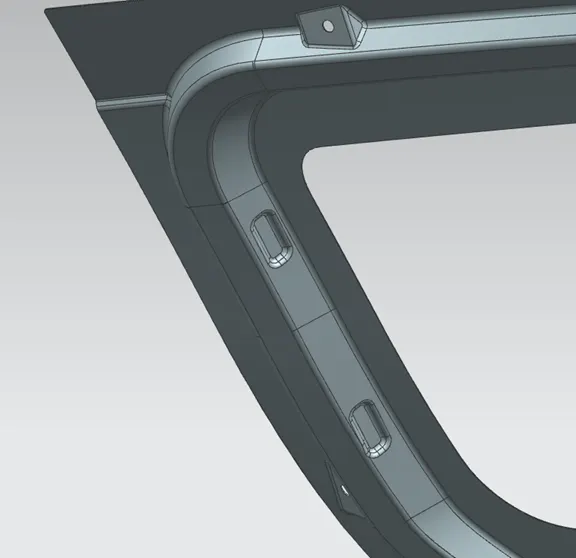
General industry dimensions from the mounting pad are used. It is to be made sure that the embosses are in the draft direction. Cutouts for hole is also given.
<!--[endif]-->
Embosses as shown
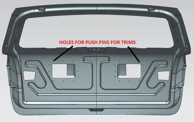
V-Emboss
DESIGN OF REINFORCEMENTS.
The reinforcements are provided because the cutouts in the mounting areas make the sheet metal panel very weak. The panels can tear quickly without reinforcements. The thickness of the reinforcement is 2-3mm. This increases the strength of the assembly while not adding a lot to the weight of the assembly.
Using the dimension for the mounting pads from the inner panel, the reinforcement surfaces are created and thickened.
The reinforcements made are:
- Hinge Reinforcements.
- Gas Stay reinforcements.
- Wiper reinforcement.
- Latch and Striker Reinforcement.
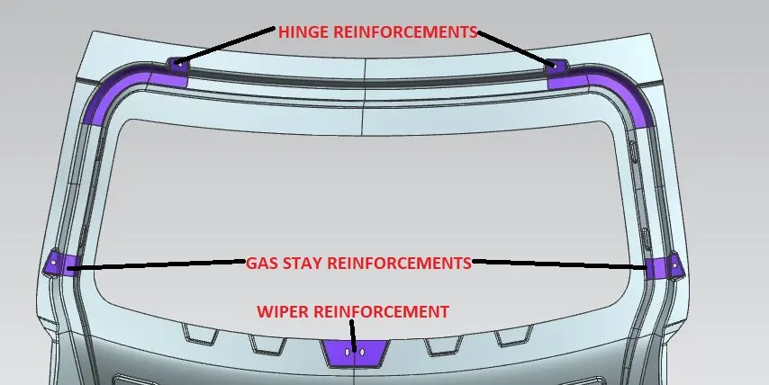
(VARIOUS REINFORCEMENTS)
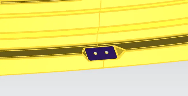
(Latch reinforcement is added in front latch and striker assembly to be mounted on it.)
DRAFT ANALYSIS OF INNER PANEL
For the deep drawing process, the inner panel needs to be analyzed if it satisfies the draft requirements.
The minimum draft angle for sheet metal component is 7°. The draft angle in the inner panel must be at least 7°.
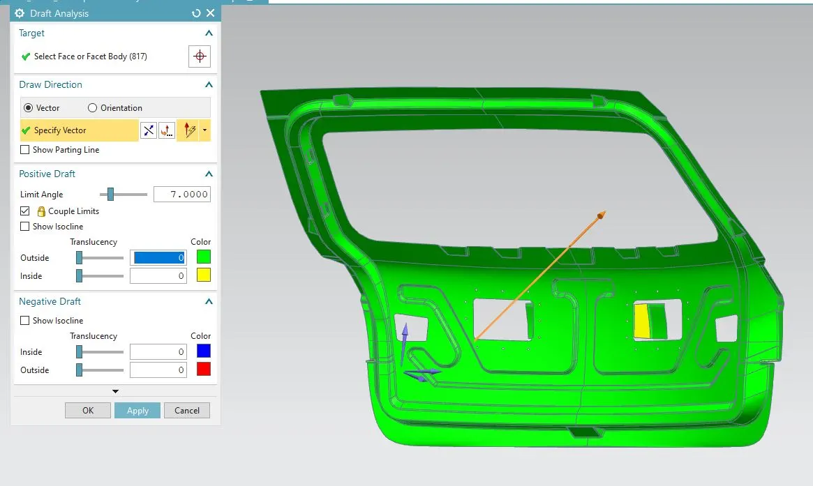 (Draft analysis of back door inner panel)
We can conclude from the draft analysis that the inner panel is suitable for deep drawing. A few surfaces that do not satisfy the draft requirements will be punched in a different process or ripped and bent later.