Base Bracket Design
REOPRT ON DRAFT ANALYSIS AND CREATION OF PLASTIC COMPONENT USING CLOSE SURFACE FEATURE.
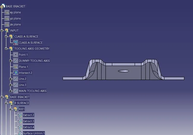
1. CREATION OF TOOLING AXIS: Tooling axis is created in the direction of pull of the core-cavity. It needs to be ensured that all the features of the part can be made using minimum number of side mould components(less side blocks) for this reason, picking tooling axis in the direction perpendicular to large surface areaa and holes is suitable.
The easist direction of pull in the base bracket is in 'z' direction, therefore the tooling axis shall be perpendicular to xy plane. Picking up a plane location whick bisects the hoe, we can intersect the class A surface wth the plane and get an outline for class a surface in the plane. The critical lines are extended and a line intersecting those lines is create as the main tooling axis.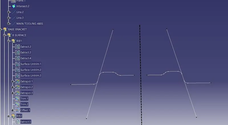
2. CREATION OF B SURFACE: After tooling axis, b surface is created usin the offset of extracte A surface and extrapolating and trimming the derived surface, fillets as required is then added. For class B surface inside fillet is outside fillet + thickness(IF= OF+THK). Outisde fillet is inside fillet - thickness(OF=IF+THK).
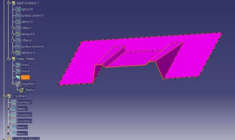
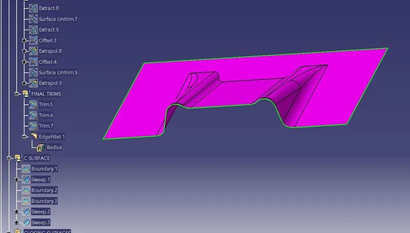
3. CLASS C SURFACE: C surface is created to close class A and B surfaces. Boundry of A surface is taken and swept keeping draft angle as a parameter. After creation of c surface, the surfaces are timmed and using close surface feature, part can be made into solid.
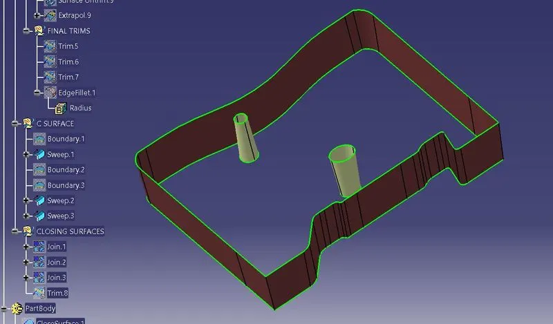
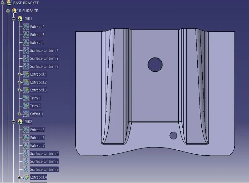
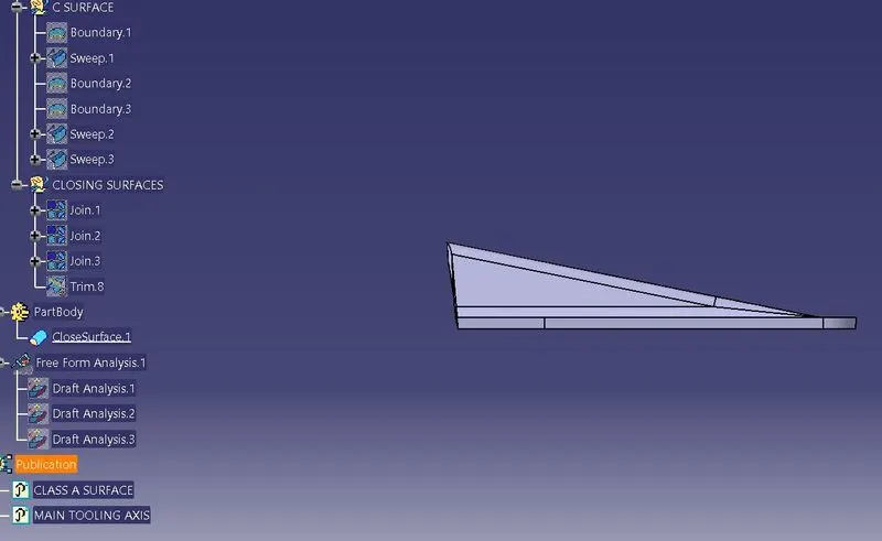
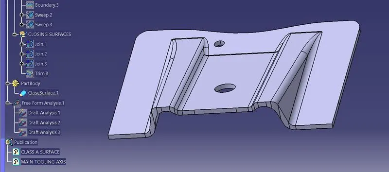
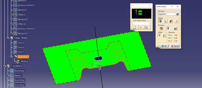
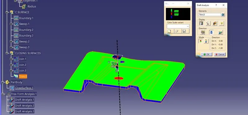
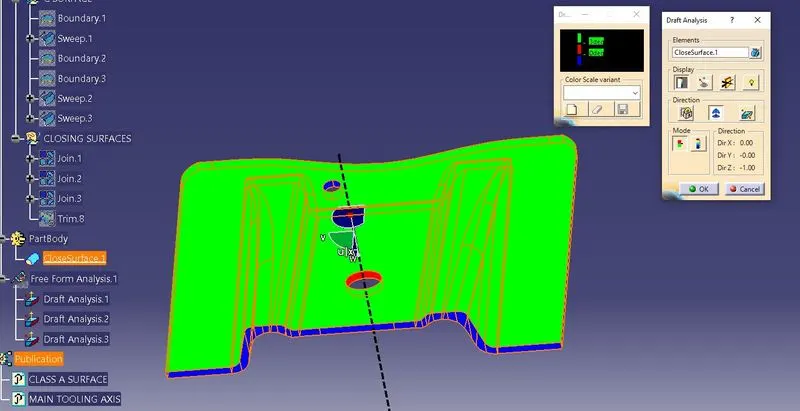
4. Draft Analysis: Draft analysis is done to study of the value of draft in the part lies in the accepted parameter or not. For this, main tooling axis is used as a reference and the part is analysed for the value of draft angles, if it falls in the prescribed angle range(>3° generally), the part is highlighted green and if not, the part is shown as blue.