Design, Assembly and application Of GD&T on Butterfly Valve
BUTTERFLY VALVE
A butterfly valve is a qauter turn control valve that serves as both throttling and on-off function valve. It is a simple valve with very few components and it can be used in high pressure application.
The butterfly valve has the following components:
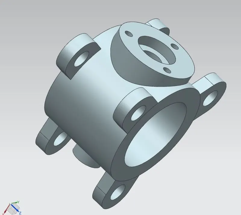
1. Valve Body: The body is the shell that contains the pressure of the valve. It is flanged or sandwitched between the opposite ends of the pipe ends.
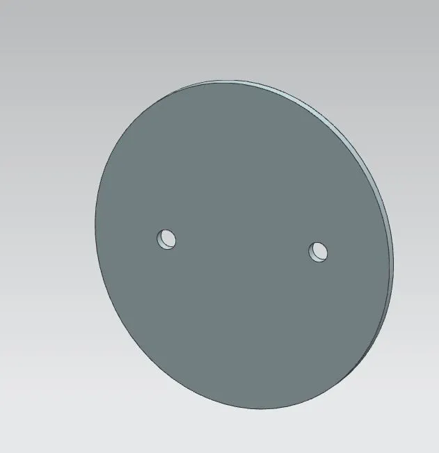
2. Valve Disc: The regulation of flow of fluid in the valve is done with the help of the disc.
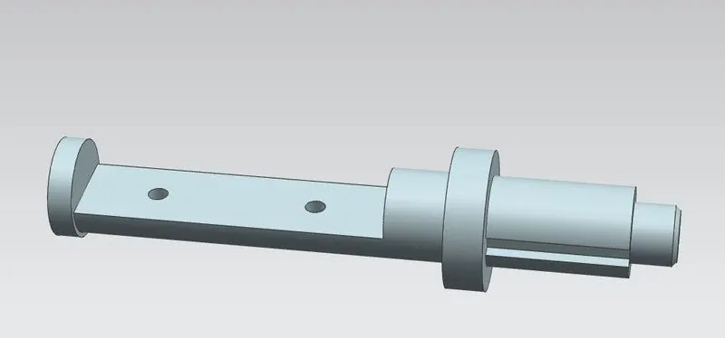
3. Valve Stem: The Stem rotates the disc helping in the regulation of flow.
4. Retainer: The retainer ensures that the stem does not blow out of the valve when high pressure is applied.
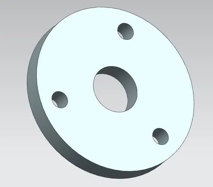
5. Lever: The hand lever is used to open/close the valve manually.
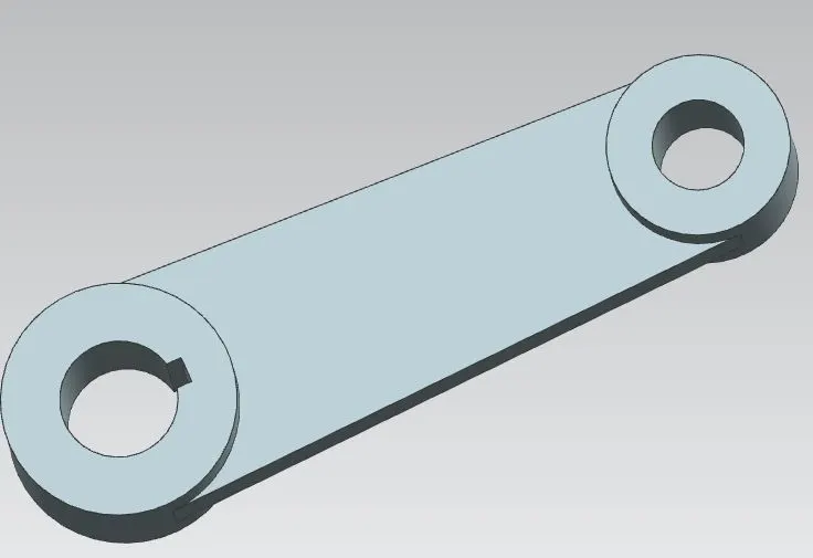
ASSEMBLY oF BUTTERFLY VALVE:
Assembly of the valve is done as follows:
1. First, open the assembly workbench and add all the parts of the valve to the assembly.
2. Move the valve components to their intended positions.
3. Align the disc with the valve shaft; aligning the axis of the holes and then joining the mating surfaces.
4. Similarly align the disc-stem subassembly with the valve body, then add the remaining components.
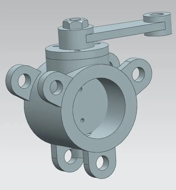
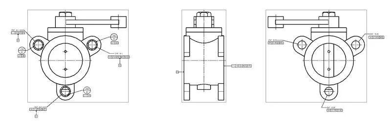
Detailed Assembly Drawing and application of GD&T.
1. Make the general assembly of the valve and add the base view and projected views.
2. The flange holes give datum target areas A1, A2 & A3. These datum targets combine to form datum surface A.
3. Give perpendicularity tolerance to any hole wrt datum A; this cylindrical hole will be marked as datum B.
3. To the other holes give position tolerance wrt datums A & B and to final hole add datum C as well. Thios feature is marked as datum D for giving out position tolerance to the flange hole on opposite side.
4. Give position tolerance to the flange hole on the far end wrt datums on near end holes.