Wiring harness design in CATIA V5 - 3D modeling Week 2 Challenge
DEFINING AND CATALOGING ELECTRICAL COMPONENTS:
Given Data: Electrical Devices:
- Deutsch DT06 – 08SA: It is female connector housing with 8pin terminal. The connector shape is rectangular and the primary locking feature is integrated with the housing.
- Tyco 174357-2 : It is female connector housing with 3pin terminal. The connector shape is rectangular and the primary locking feature is integrated with the housing. It also has features attache to mounting clip.
- Tyco 85229-1: It is a Mounting Clip; MOC: PA.
Defining as Electrical connectors:
Deutsch DT06 – 08SA:
- The CAD (STEP) file is downloaded and saved as a 'CATPART'.
- Points for bundle connection is made. The wires entering the connector will terminate at this point.
- Connector connection point is created in the center of the face where connector will be placed.
- An Axis system is created with the connector connection point such that the Y axis is perpendicular to the face, X axis is aligned with the locking mechanism.
- After this, the part is opened in electrical design workbench. Here We define the component as a connector.
- After defining the component as a connector the connector connection point and the bundle connection points are defined.
- The component is then added to a catalog for connectors.
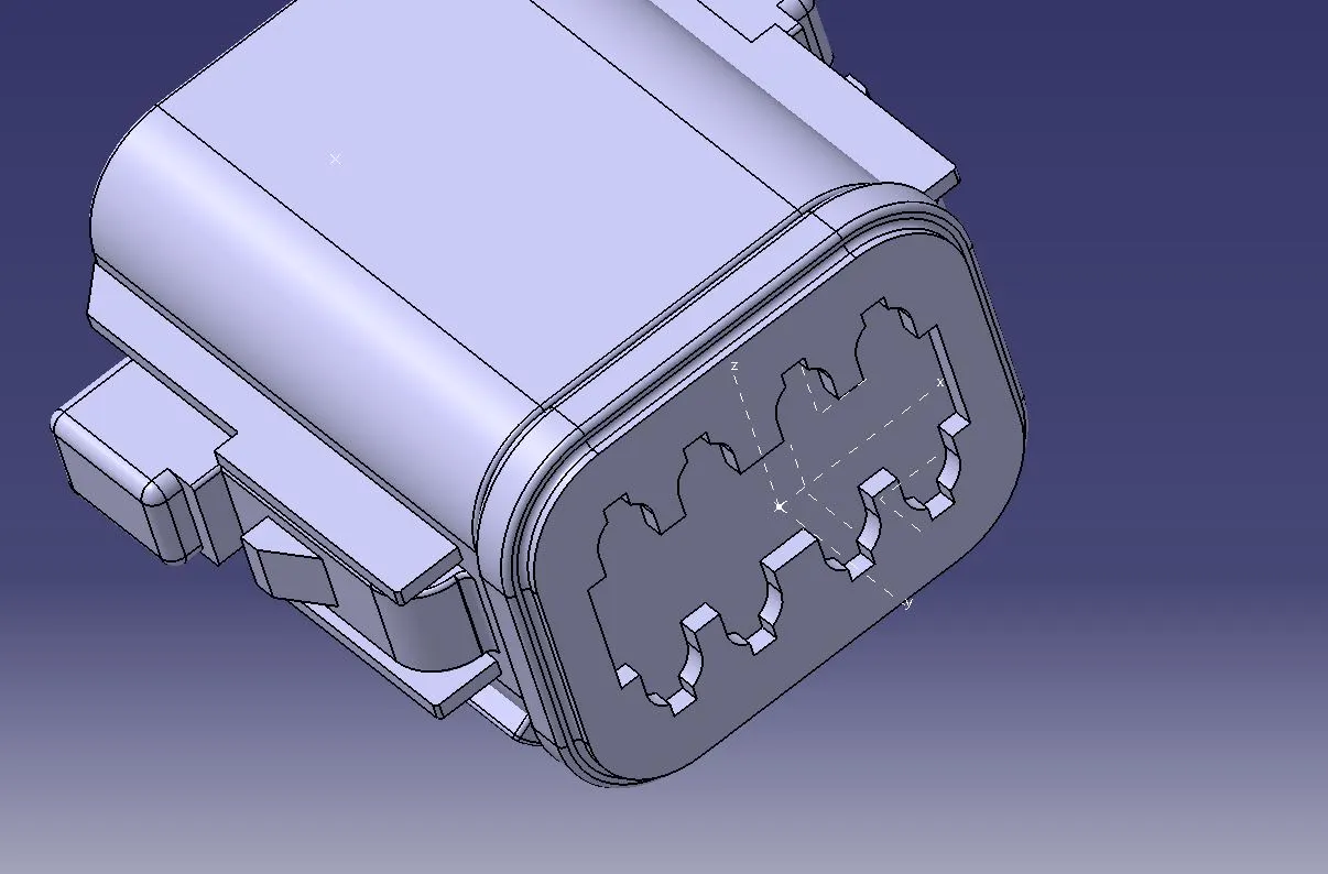
(Connector connecing axis for the 8 pin connector shown)
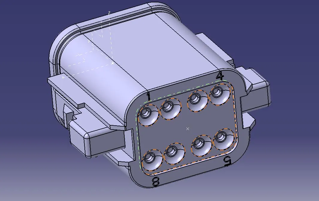
(Bundle connecting point of the 8 pin connector)
Tyco 174357-2 :
- The CAD (STEP) file is downloaded and saved as a 'CATPART'.
- Points for bundle connection is made. The wires entering the connector will terminate at this point.
- Connector connection point is created in the center of the face where connector will be placed.
- An Axis system is created with the connector connection point such that the Y axis is perpendicular to the face, X axis is aligned with the locking mechanism.
- For the placement of the clip, a point is made on the edge of the mating surface in the middle. Using this an axis system is prepared fro the clip mointing. The axis system should be compatible with the connection connection axis.
- After this, the part is opened in electrical design workbench. Here We define the component as a connector.
- After defining the component as a connector the connector connection point and the bundle connection points are defined also cavity connection point is defined.
- The component is then added to a catalog for connectors.
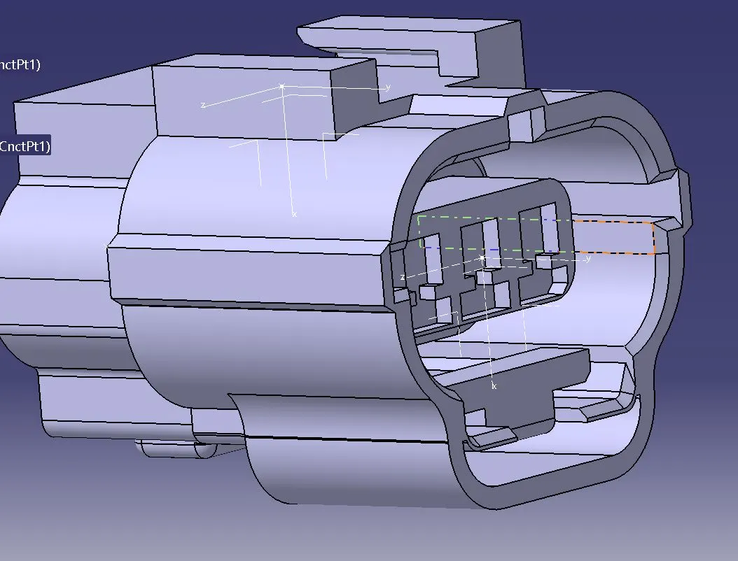
(Connector connecting axis of the 3 pin connector)
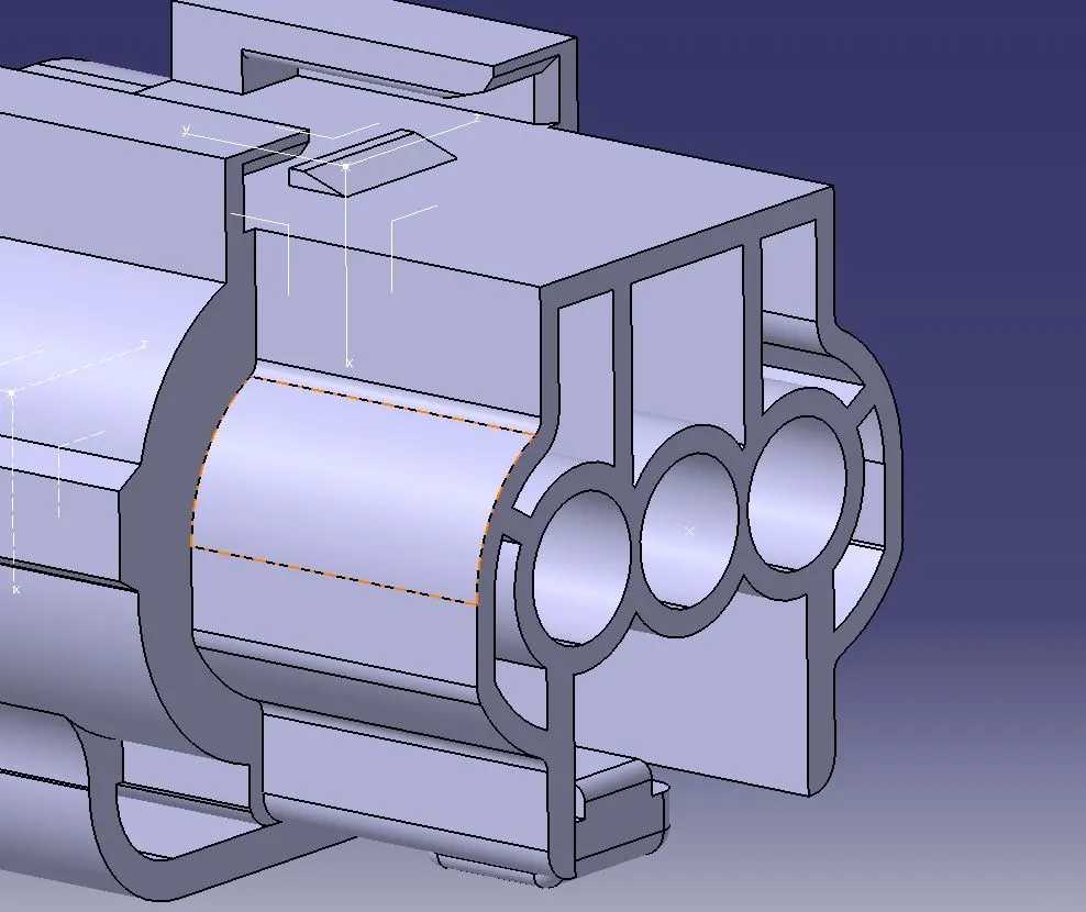
(Bundle connection point and the cavity connecting axis of the 3 pin connector)
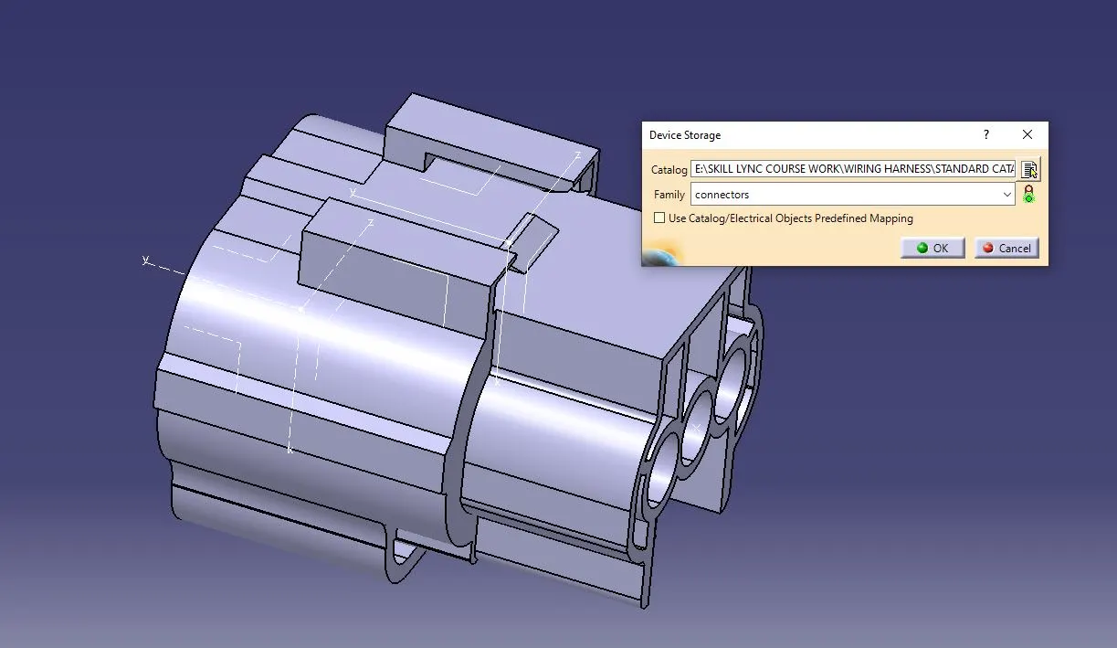
(Adding the connector to the catalog)
Tyco 85229-1 :
- The CAD (STEP) file is downloaded and saved as a 'CATPART'.
- A point is created on th edge of the mating surface with which an axis system compatible for mounting with the 'Tyco 174357-2' clip mounting axis system is created.
- The part is opened in electrical design worknbench and is defined as a mounting equipment.
- The define cavity tool is then used to defing the orientation of the axis to be mounted with the Tyco 174357-2 connector.
Assemblying Tyco 174357-2 and Tyco 85229-1
- We need to assemble the connector housing and the mounting clip. For this we use the Electrical assembly Design WB. Using the tool Connect electrical devices, the connector and the mounting clip are mounted onto each other.
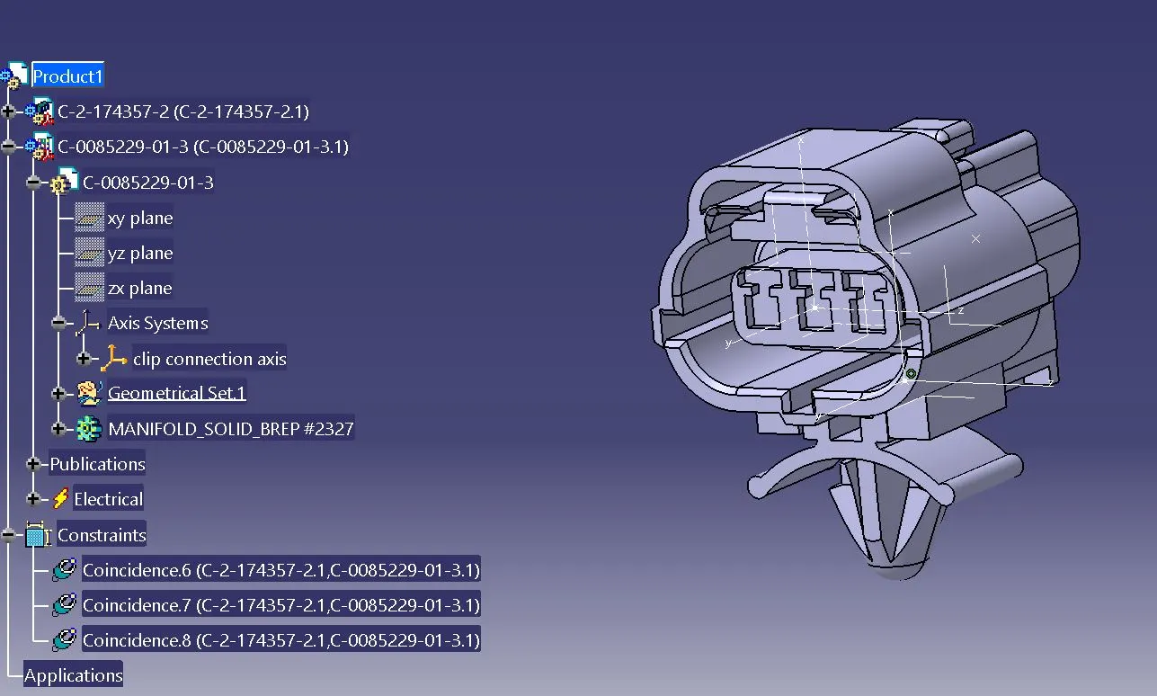
(Creation of connector and mounting clip assembly)