Week 12- Final project
LOWER DOOR TRIM COMPLETE DESIGN:
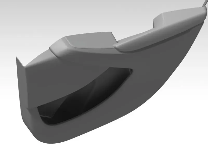
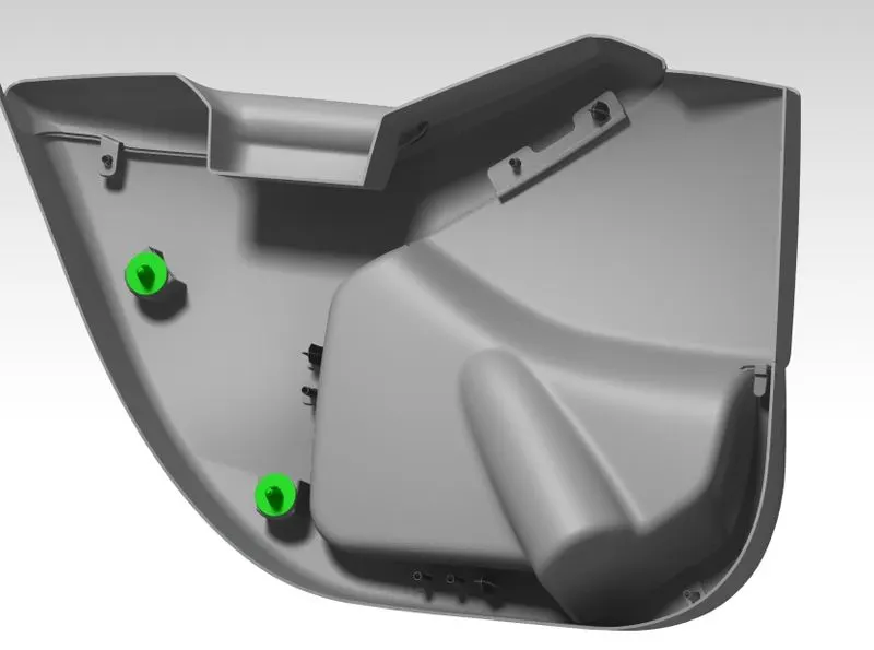
Aim: To design the lower door trim of a car from a class A surface and master sections complete with the correct engineering features.
Overview:
Door Trim is the interior part of the door, it is used to cover the door panel and to provide features, tools and comfort to the passengers. While designing the door trim, we have to keep in mind that the door trim not only is functional but has to be aesthetic as well.
Objectives:
- To make individual component from the given Class-A surfaces.
- To make the part bodies of the components with the appropriate thickness from the master section.
- To make flanges using the given master section.
- To create the B side features for attachment of the part to the assembly.
- To create and study the draft analysis for the final part ensuring the parts are manufacturable.
Tool Used: CATIA V5.
Introduction: In this project, a lower door trim is to be designed using a given class A surface, the parameters for the design are as follows:
- Part thickness: 2.5mm for all parts
- Draft angle: 3°
- Flanges shall be created as per the master section provided.
- Design Guidelines of B side feature is given as:
- Draft - 0.5 degrees on the walls of boss for locators, heat stake and dog houses.
- Nominal Wall thickness for heat stakes and locators: 1mm; for dog house: 2mm.
- Thickness at the base- Typically 40% of the nominal wall thk. for dog house.
- Height of the dog house feature: 20mm
- Height of the base ‘c’: 3 to 6 mm for dog house.
- Fillet Radii - 0.25mm maximum radii.
- Locators shall have entry chamfer and shall be higher than the heat stakes.
- Dog house shall be created keeping in mind the dimensions of the standard push pins.
The parts are developed keeping the aforementioned parameters in mind while creating the part body and the engineering features.
Constraints:
- Changes if any in Class A surface shall be very minimal.
- Part thickness cannot deviate more than 30% of the nominal thickness in any direction.
- All design rules shall be followed strictly.
- All surfaces shall be completely closed before converting to solid. A maximum tolerance of 0.003mm is allowed.
- Minimum draft on the B side feature walls is 0.5°.
Report:
- Class A surface:
The following surface is given as the input for the creation of the part. This will be the main aesthetic surface for the door trim.
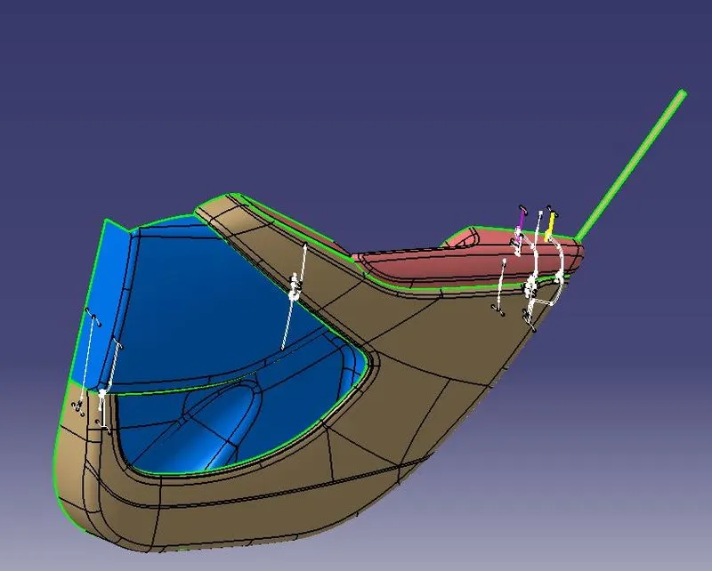
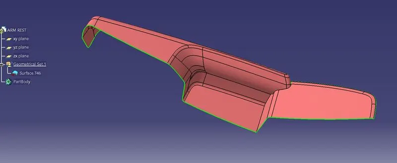
(Arm rest)
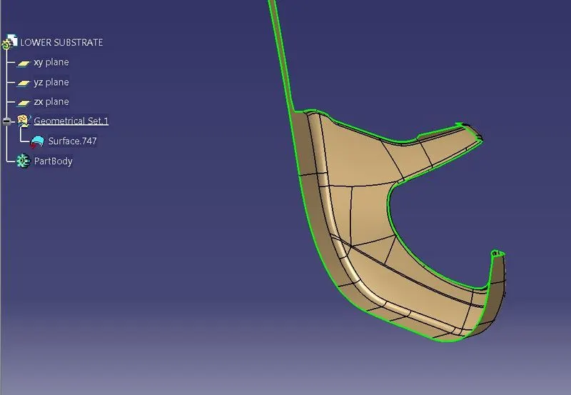
(Lower Substrate)
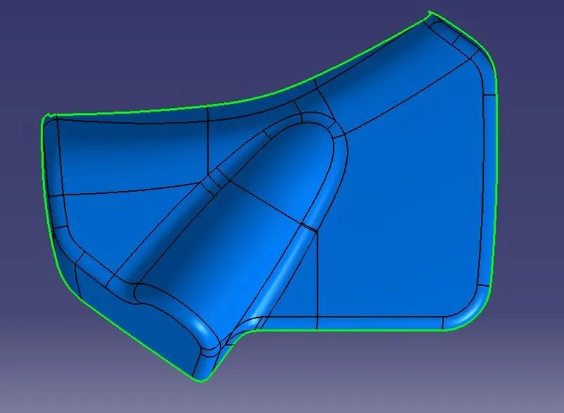
(Map Pocket Lower)
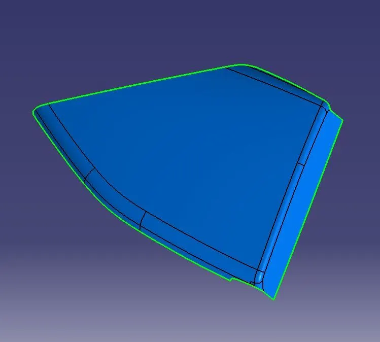
(Map Pocket Upper)
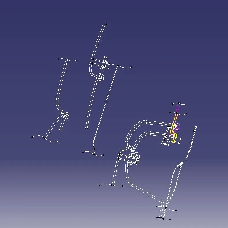
(Master Sections)
- Defining individual components:
The Class A surface of the lower door trim has the following individual components:
- Lower Substrate
- Map Pocket Lower
- Map Pocket Upper
- Arm Rest
These components need to be designed separately, all engineering features shall be made such that assembly can be done with the main assembly and with each other.
- Creation of individual components:
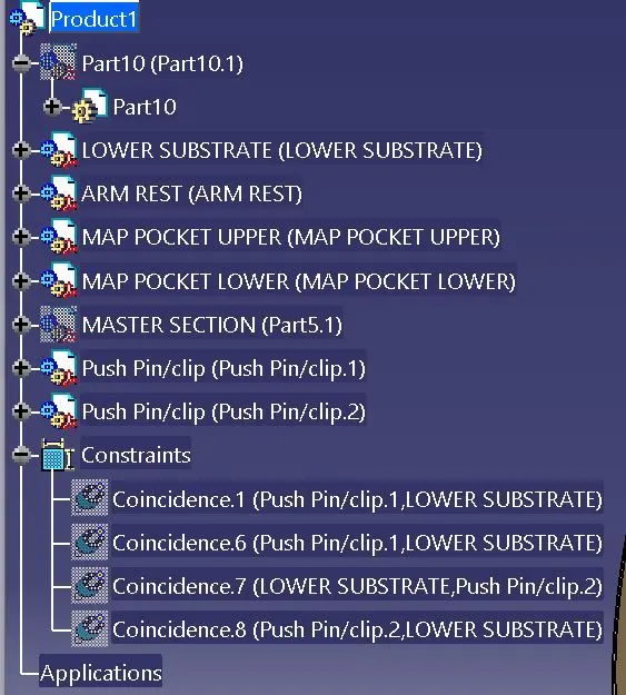
- In the Product workbench, create new component; Take the corresponding surface for any individual component such as Lower Substrate and paste it as an input for the new component.
- Repeat this step for all the components and the master section.
- Designing for individual Components:
- All the individual components need to be designed by the closed surface method.
- Creation of Tooling Axis and performing Drft Analysis of class A Surface.
- With the class A Surfaces for all individual components, we can create tooling axis for the components.
- By visual inspection, we can see that all the components have y axis as the tooling direction. This is because, the components are assembled in y axis itself.
- Create tooling axis for Lower substrate, map pocket upper, map pocket lower and he arm rest in the generative shape workbench.
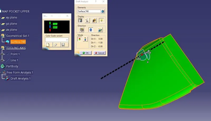
- A few surfaces have draft angle lower than 3°, this can be acceptable for a small area as changes in Class A is not allowed.
- Arm Rest surface has multiple tooling axis in y direction and for the top part in z direction. This is because the arm rest surface is actually two different components shown as one.
- Perform draft analysis on class A surfaces.
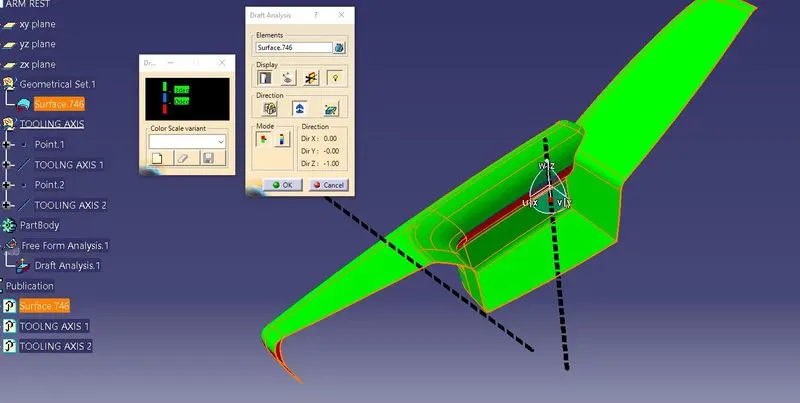
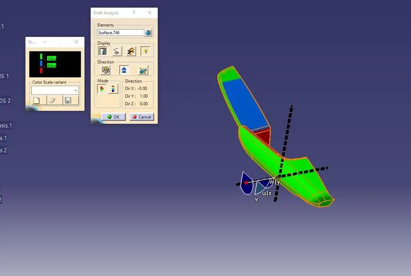
(Two tooling axis need to be created as the part is made with either a side core or two parts are joined together and presented as one)
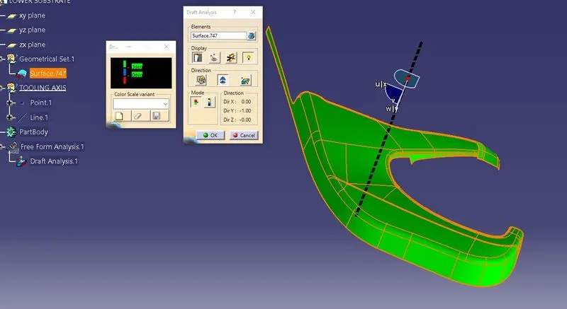
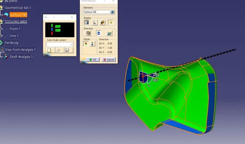
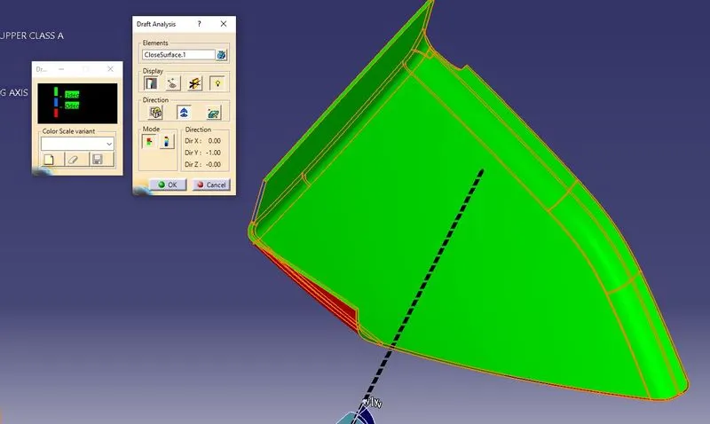
(Draft analysis shows that some surfaces do not conform to atleast 3° draft angle, we can request for change in class A surface or proceed as it is as we can accept a few surfaces with draft angle below 3° but not negative draft angles )
b. Creation of Class B surface:
- Class B surfaces are created by offsetting the class A surface to the appropriate part thickness which is 2.5mm for all parts in our case.
- After the surface is offsetted, we correct the missing patches if any.
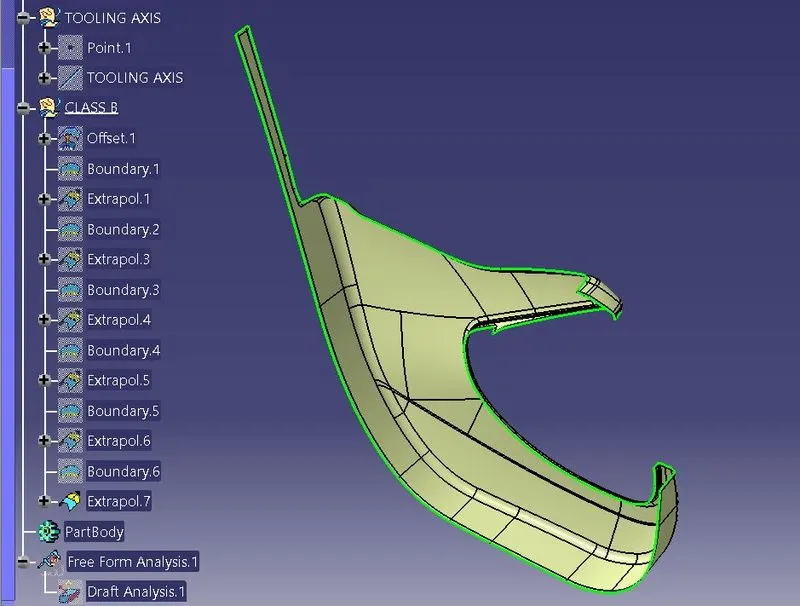
(Lower Substrate Class B)
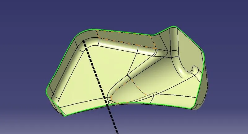
(Map Pocket Lower Class B)
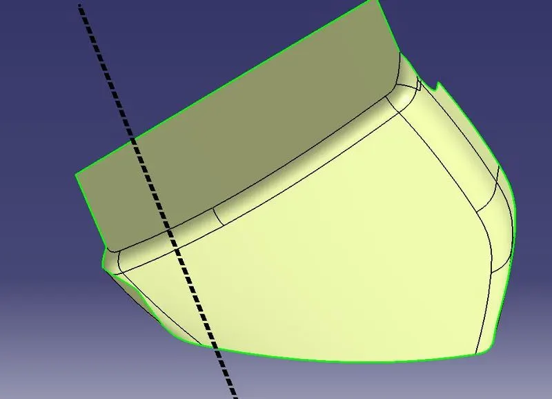
(Map Pocket Upper Class B)
c. Creation Of Class C surface:
- Class C surface is created by extracting the boundaries of class A surface and using the sweep command perpendicular to the class A surface.
- It can take multiple sweep operations to create the proper class C surface.
- Join and trim all the sub-surfaces of class C together to get a seamless class C surface.
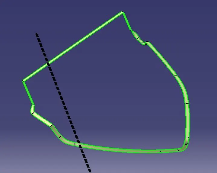
(Map Pocket Upper Class C)
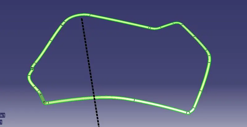
(Map Pocket Lower Class C)
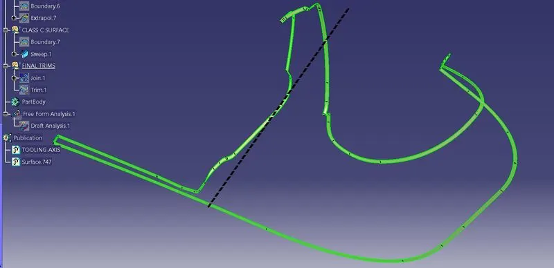
(Lower Substrate Class C)
d. Creation of Close surface for part body:
- After creation of class B & C surfaces, trim all the surfaces (Class A, B & C) together.
- For this, we need to first join the class A & C surfaces and then extrapolate it, also extrapolate the class B surface and trim the surfaces (class A+C and Class B) together.
- This will produce a close surface ready to be made into a part using the close surface command in the part workbench.
e. Creation of Part Body:
- Part body is created by using the close surface command in the part workbench.
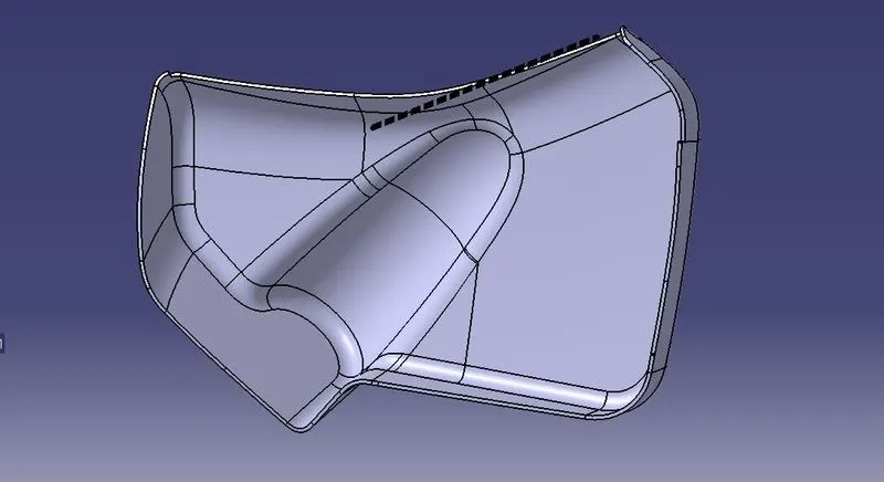
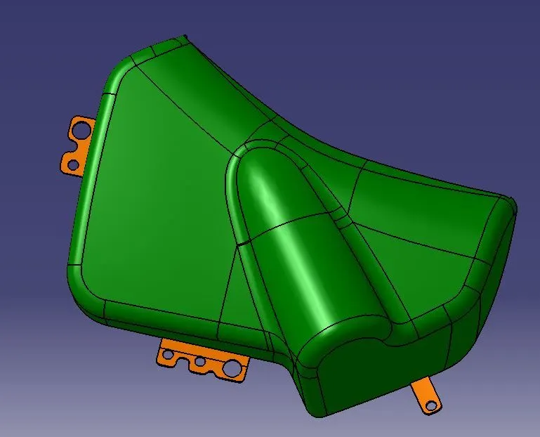
(Map Pocket Part)
f. Draft Analysis on the part:
- Draft analysis is done on the final part as well to ensure the manufacturability of the part body.
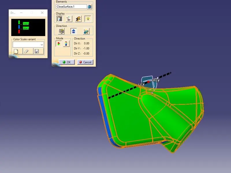
(Similar to Class A, Draft analysis shws a few surface with draft angle less than 3°)
g. Creation of B side features:
B side features are created for assembling the components. In the case of the lower door trim, it is clear that only lower substrate is used to attach the door trim to the door panel hence the B side features will be on the lower substrate only.
Taking the class A surface of the lower substrate and extrapolating the surface on the inside, we can get a boundary for the creation of B side feature. Extract the boundaries and create multiple points on the extracted curves. These points will serve as a location of the B side features.
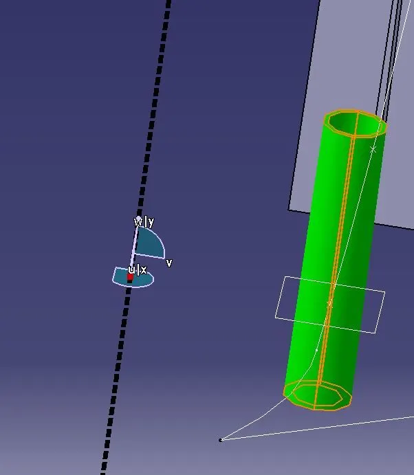
- Creation Of Heat Stakes:
Heat Stakes are created for joining the components together. Heat staking is done by melting the base plastic material into a shape that will hold the secondary component.
- We have to design heat stake with wall thk.: 1mm, so I take OD: 7mm & ID: 5mm.
- Using a point on the created boundary as reference and the zx plane, create the sketch for heat stake and pad in a part named heat stake.
- Draft the heat stake and copy and paste for all the instances you want the heat stakes to be copied.
- Translate the heat stake body to all the desired points.
- Creation Of Locators:
Locators are created for guiding the components into the secondary component. Locators also help in arresting the degree of freedom of the component. The height of locator should be more than that of heat stake.
- Using a point on the created boundary as reference and the zx plane, make a sketch for locator, so I take + shape of 15mm x 15mm.
- Draft the locator and copy and paste for all the instances you want the locator to be copied.
- Translate the locator body to all the desired points.
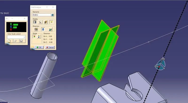
- Creation Of Dog House:
Dog Houses are created for insertion of push pins in our case. Dog house raise the height fro features that require height. They do not create sink marks.
- Using a point on the created boundary as reference and the zx plane, make a sketch for dog house.
- Making a sketch on the flat surface of the body, position the line where the dog house is desired.
- Extrude the sketch to make a surface, thicken the surface making sure that it intersects the main body.
- Using the dimension of the push pin, create the supports for the push pin on the dog house.
- Using the copy and translate tool, make the dog house at other locations.
- Perform draft analysis on the part obetained for dog house with atooling axis perpendicular to the dog hous
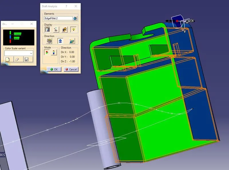
- Assembly of engineering features with the part body:
Engineering features need to be assembled with the part body..
- Using the union trim command, join all the created engineering features with the part body, specifying the faces to remove for the heat stakes, locators and the dog house.
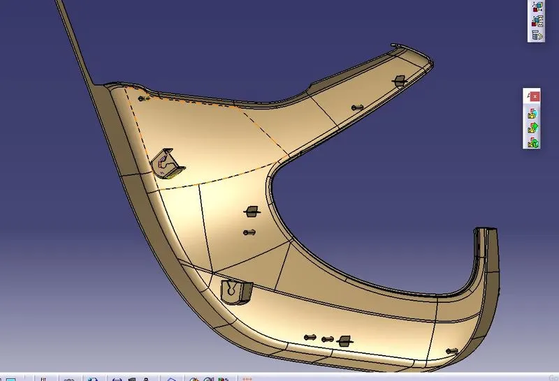
- Creation of Flanges:
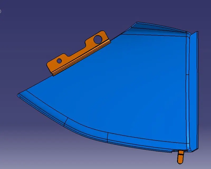
Flanges are created to interlock the components together in subassembly. We have to follow the master section to create the flanges.
- Extract the elements from the master section and the faces the flanges are attached to.
- Using these extracts, sweep and trim an outline for the flanges. Close the flanges and assemble with the part body.
- Make holes where required. This completes the part body design.
- Do this for all parts wherever necessary.
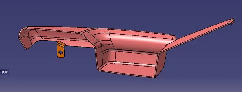
- Assembling the door trim:
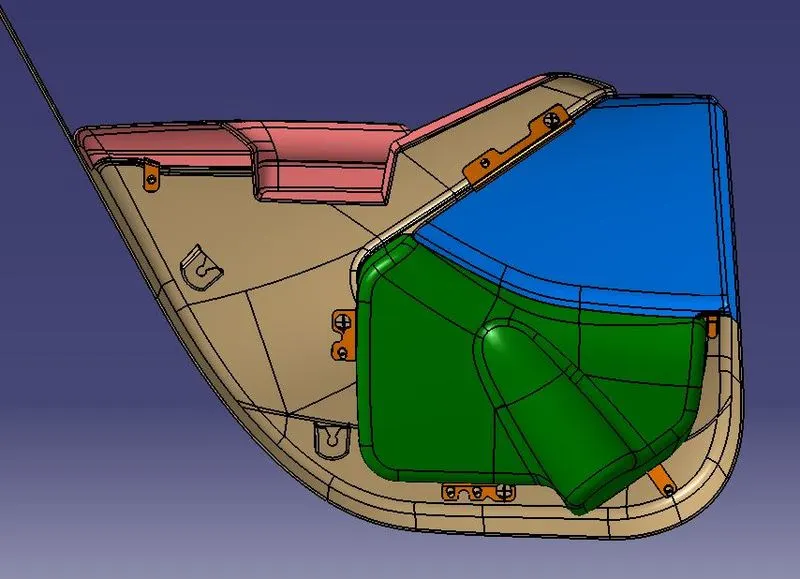
- As the reference for the part was taken from the assembly itself, the door trim shall already be assembled.
- If not, use the assembly constraints to assemble the individual parts.
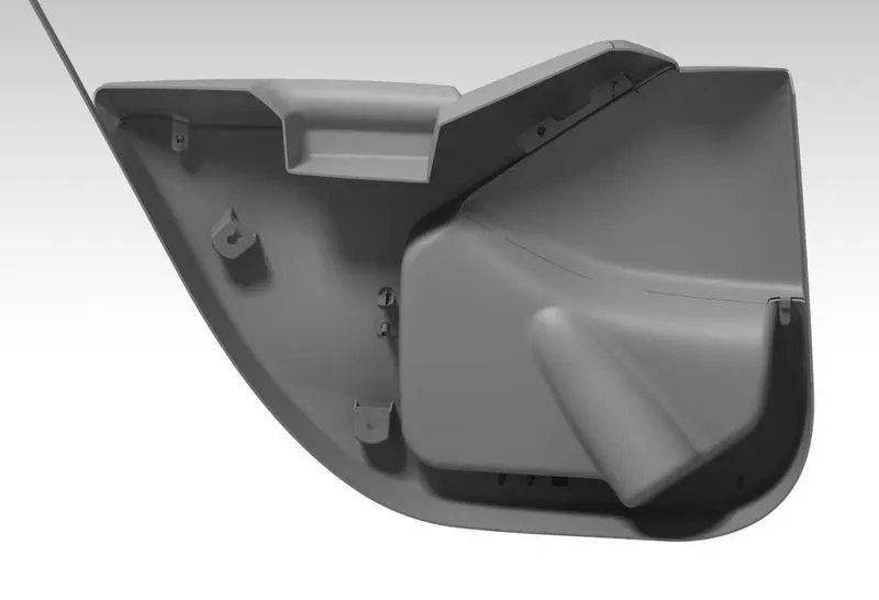
Render the product using render tool after applying appropriate material.
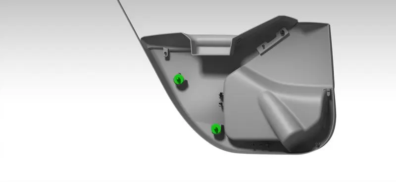
- Conclusion:
- The assembly of the door trim is complete with all the flanges for interlocking and the Engineering features.
- All the individual components are designed using the close surface method for the part body.
- All design rules are followed while designing the parts and the B side features.