Fender Design
DESIGN OF FRONT FENDER OF A CAR
ABSTRACT
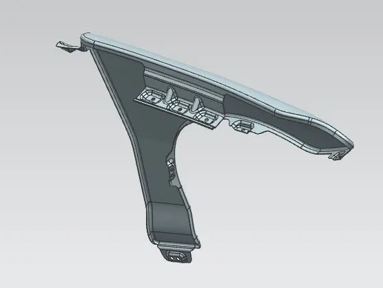
The fender is a frontal BIW closure component of the car. Fender is the US English term used for the automobile component that covers the wheel wells of the car. The fender provides a shield to the car underside, inner (engine bay area) and the pedestrians from the gravel, water and mud hurled by moving wheel of the car. Fenders are made of steel/aluminum sheets or thermoplastics for most of the cars.
INTRODUCTION
The fender is one of a styling component which is exposed and thus must be designed aesthetically. Therefore welding process cannot be used while mounting the fender to the peripheral components. Therefore, flanges are provided in the mounting areas that join the mounting surface with help of fasteners. The mounting flanges are hidden so that fasteners are not visible, improving the vehicle aesthetics.
The mounting points for the fender are:
- Drip Area
- <!--[endif]-->A-Pillar
- <!-- [if !supportLists]-->Bumper
- <!-- [if !supportLists]-->Sill
- Wheel Well
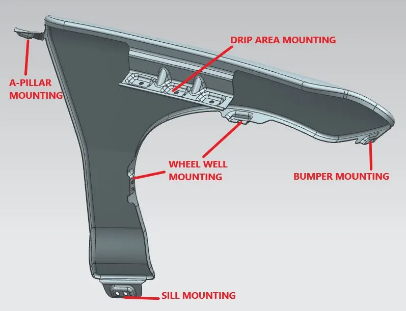
The main objective of this report is to explain the design of mounting areas for all the aforementioned mounting points, showcasing the engineering considerations for the design of the mounting areas.
The Class-A surface of the fender and the master section for the design of the drip area is provided. The drip area must be designed as per the provided master section. Other mounting areas are designed in such a way that ensures the proper mounting with the adjoining components.
DESIGN OF FENDER
DESIGN TOOL USED: SIEMENS NX
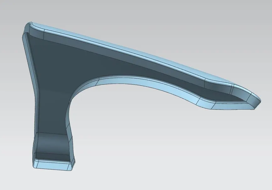
(CLASS A SURFACE)
DESIGN OF DRIP AREA
The drip area of the fender mounts the fender to the engine compartment. It is the most important mounting position for the fender.
- The considerations for the design of the drip area are:
- A minimum of 200mm distance should be present from the rear mounting position of the fender to the end of the drip area. This is done to leave space for the cowl mounting.
- A minimum of 150mm distance should be present between the fronts of the fender to the drip area. This is to ensure that the proper installation and mounting of headlamps.
- There must be at least 200mm gap between the hood open position and the mounting surface of the drip area for proper functioning of the tool.
- The total length of the mounting flange must be less than 40mm, this is to reduce the spring back effect in sheet metal.
- A gap of 8mm is given between the hood and the fender flange to ensure that the components do not contact while opening and closing the hood.
- The flange is made at 3°, this ensures that the engine compartment is not visible from the gap between the hood and fender.
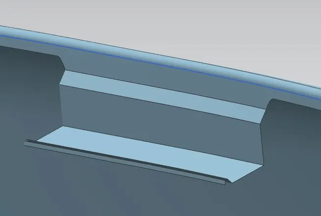
(DRIP AREA FLANGES)
DESIGN PROCEDURE FOR DRIP AREA
The drip area is designed using the master section and the design considerations mentioned before.
- Planes at 200mm from the rear of the fender and 150mm from the front of the fender are made and intersection curves are generated using the flange surface and the planes.
- Using the offset curve in face command is used to generate a curve 5mm from the start of the flange then curves in the flange are generated as per the desired design of the flange. The flange is then trimmed using these curves.
- Following the master section and using the law extension command, the drip area is prepared. The necessary face blends are provided.
- Using 3 points in joining surface, a plane is created for emboss. The emboss is sketched in the plane and projected to the mounting surface, using the emboss command in the lower side, the emboss for mounting is created taking offset from the previously created plane to 4mm. This ensures that the mounting surface is flat and not curved.
- The hole for the fasteners is then trimmed out of the surface.
- Ribs are provided for structural stability.
- Face blends are then made in all the required surface. The best practice for providing blends is that the fillet radius must be at least: sheet thickness + 3mm. In this case sheet thickness: 0.75mm. So minimum of 3.75mm radius to be provided.
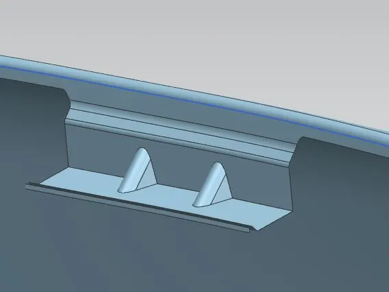
(DART)
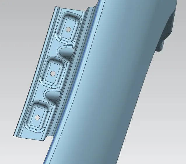
(DRIP AREA WITH DART, EMBOSS AND CUTOUT FOR TOOLING)
DESIGN OF A-PILLAR MOUNTING
A-Pillar mounting flange joins the rear of the fender to the A-Pillar.
Master section is not provided for the A-Pillar mounting. The mounting condition is assumed as per the engineering consideration and best practices.
- Similar to the drip area, the desired flange dimensions are created using curve in face and the excess is trimmed.
- Using law extension, the flange is projected upwards to meet the A pillar.
- The projected sheet is then trimmed to the desired shape and using three points in the flange, a plane is created and emboss are created similar to that in drip area. The hole for mounting shall have the same dimension as that of the drip area (5mm) for standard fastener to be used.
- Radius is provided to then surfaces.
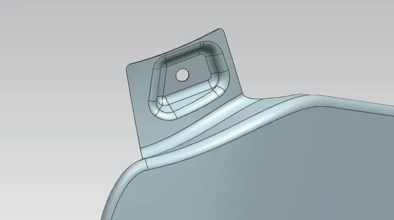
(A-PILLAR MOUNTING)
DESIGN OF BUMPER AND WHEEL WELL MOUNTING
The design for all bumper, sill and wheel well mountings is very done in the same way.
- The desired flange dimensions are created using curve in face and the excess is trimmed.
- The provided flange of 20mm is enough to create the mounting for bumper and wheel well.
- The flanges are trimmed to the desired shape and using three points in the flanges, a plane is created and emboss are created similar to that in drip area and A-Pillar mounting. The hole for mounting shall have the same dimension as that of the drip area (5mm) for standard fastener to be used.
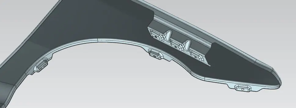
(WHEEL WELL AND BUMPERMOUNTING)
DESIGN OF SILL MOUNTING
- The Sill mounting flange mounts the fender to the door sill.
- Flange of desired shape is trimmed and using law extension it is extended in the downwards direction.
- Emboss and cutouts are created similar to other mounting areas.
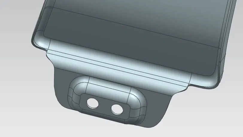
(SILL MOUNTNG)
RESULT AND CONCLUSION
The final component is ready and draft analysis can be done to check the manufacturability of the fender. The drip area is designed as per the master section and the mounting flanges for other mounting areas are designed as per the best engineering practices.