Hood design-Week 2
CAR HOOD DESIGN
AIM: To design a car hood from Class-A surface of hood outer panel. For the complete design of the hood, the following task is needed to be done:
- Preparing the design for outer panel with the hem.
- Design of inner panel according to given master section, provide the embosses and cut-outs for pedestrian safety and impact distribution.
- Provide reinforcements for hinge and striker area.
- Prepare the mastic data.
- Position the hinges and striker and study latch trajectory.
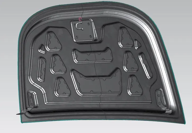
Introduction: Car Hood or the bonnet is the frontal BIW enclosure component. It is hinged and can be opened to access engine or the front trunk (frunk). The hood covers the engine components. It reduces the air resistance to the movement of the vehicle, making the car more aerodynamic. A good bonnet design will distribute the impact of collision to the side of the vehicle so that the impact in the cabin is reduced. A bonnet should also be designed keeping the safety of pedestrians in mind. The bonnet shall be designed in such a way that the impact on the pedestrian is the least if the car hits them. For this, sufficient clearance is to be provided between the hood outer and inner panel.
Considerations: Following are the considerations while designing the hood parts:
- Thickness of sheet: 0.75mm. Thickness of reinforcement: 1.5mm.
- Min. Blend radius for all edges of emboss:3+sheet radius: 3+0.75=3.75.
- Gap for Mastics: 5mm between inner and outer panel.
- Relief to be provided in the corners of hems for stress concentration reduction.
Hood Design:
- Inner Panel:
Inner Panel is designed using the offset of the outer panel and the master section. Also the mounting positions of the hinge assembly and the striker are considered while designing the inner panel. The following steps are involved in designing of the inner panel.
A. Offsetting Outer panel surface and creating the Inner Panel outline according to the master section:
- Refer the master Section and offset the Surface for 2 mm. Trim the surface using the middle datum plane for ease in designing.
- Use curve in plane command to offset the outer edge of the surface to 20mm.
- Use Trim sheet and select the curve in surface as the boundary and keep the outer surface.
- Similarly do this for both offsets and join them using through curve extension method.
- Give a face blend of about 5mm, it should be 3.75mm min as stated in considerations.
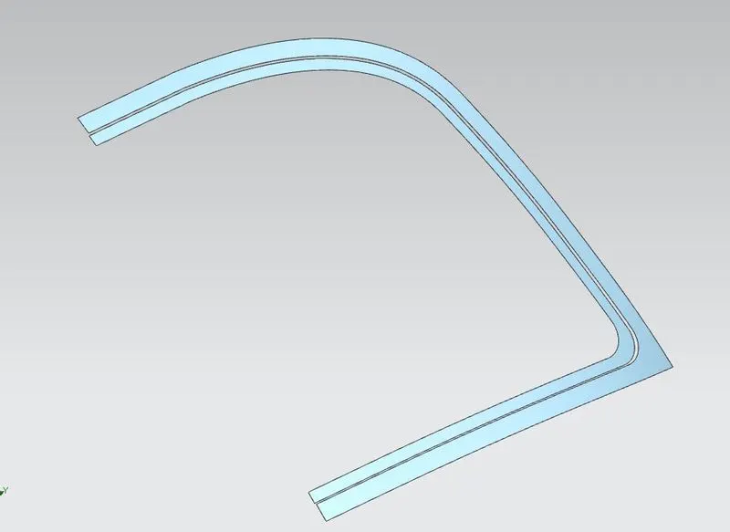
(Curves Offsetted setted in face and trimmed as per master section for inner panel)
B. Creating emboss for material removal and weight reduction:
- Emboss needs to be created for getting the hood assembly structurally stable as well as for it to be lightweight.
- Create a sketch in the plane perpendicular to the inner surface. The top and bottom points of the hood are used to make a line and the line perpendicular to this line is our tooling direction as it will be perpendicular to the inner surface.
- Now make a sketch in the plane parallel to the inner surface and use the dimension of the mounting faces of striker and hinge assembly and make the sketch accordingly.
- Now project the sketch onto the inner surface and give emboss with the tooling direction and draft angle.
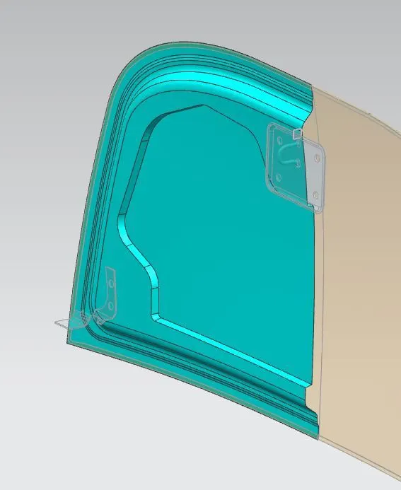
(Inner panel with emboss created)
C. Creating emboss for mastics:
- The inner and the outer surface need to be 5 mm apart for application of mastics. Mastics are oil based sealant used to provide structural strength while being soft enough for not to add significantly to head impact and mess with crumple zone.
- According to the Old data and after simulation we need to provide where to put structural support. As the crumple zone needs to spread outside of the car, more support is needed in the centre so that the impact spreads around the region where more support is given.
- Create the sketch in the plane parallel to the inner panel for where emboss is required.
- Using the emboss command with the tooling direction, create the required emboss.
- Use the Edge blend/Face Blend command to fillet the edges of the created embosses.
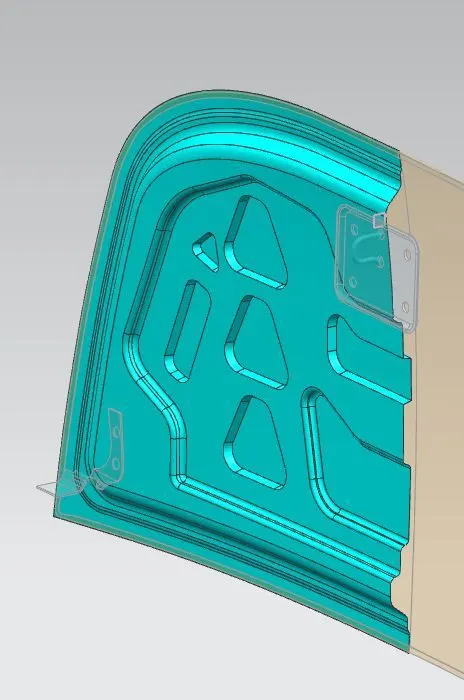
(Emboss for mastics)
D. Creating Cut-outs in hood inner panel:
- Cut-outs are made in the hood inner panel to save the weight and pedestrian safety as impact is greatly reduced with cut-outs in the inner panel.
- Create a sketch and offset the sketch for emboss in plane parallel to the inner panel. Make circular extensions for the application of mastics in the inner panel.
- Project the curve onto the emboss surfaces one by one and trim the inner panel.
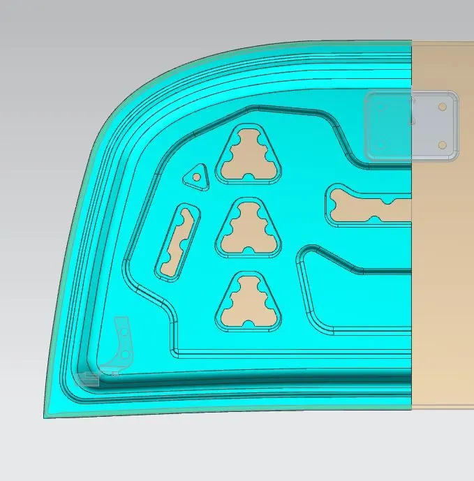
(Cutouts created and surface mirrored and sewed)
E. Creating Hinge Assembly Mounts:
- Hinge assembly needs to be mounted on a flat surface and as the hood inner panel surface is a curved surface, we need to emboss the surface such that a flat face is achieved for proper mounting of hinge assembly.
- Use the datum plane parallel to the inner panel and create a new plane at a distance from the inner panel surface. This plane will be used as the reference plane for hinge mounting.
- Create a sketch in this plane for the approximate dimension of the hinge assembly mounting area and project it on hood inner panel surface.
- Now emboss this sketch and change the end connection to the plane created earlier. Give a draft direction of about 8°.
- Now a flat surface is created, make blend to give proper radius to sharp edges.
- Now assembly can be activated and hinge can be added to the assembly and constrained with the inner panel.
- Remember to fix the outer and inner panel before giving assembly constraints to the assembly or they will move.
F. Creating Strike/Latch Trajectory:
- We need to assemble the striker in such a way so that the striker is always tangential to the hinge axis for best closing of the hood.
- For this, use wave geometry linker to extract edges from the hinge assembly along which the hinge rotates and make points in the centre of those circular edges. Make a line from those points and we get the hinge axis.
- Make a plane in the centre of the hinge axis and make a circle with centre as the hinge axis projection. This is our rough trajectory of the hood.
- Make a line at about 82° from the horizontal and make tangent line through intersection point. This line shows the direction of striker hook.
- Now add striker to the assembly, making it work object, make a line through the striker hook in its centre. This line is the striker axis.
- Align the striker with the inner panel such that the striker axis and trajectories aligned and striker is positioned in correct manner.
- Make changes in striker trajectory circle, angle if required.
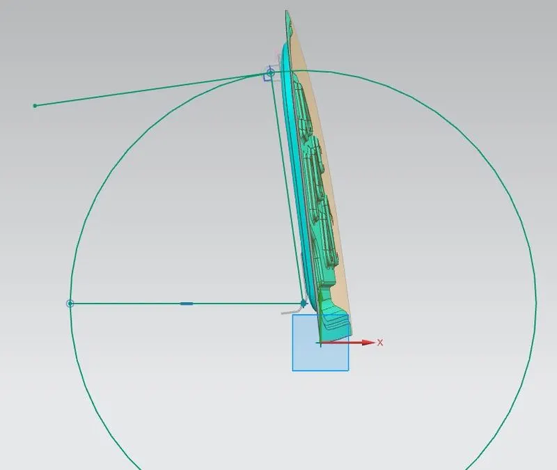
(Striker Trajectory)
G. Creating Striker Mounting:
- Similar to hinge mounts, striker needs to be mounted on a flat surface. And as the striker’s mounting surface is already flat, we can extract the surface.
- Using the surface extracted with the help of wave geometry linker and extending the extracted surface, we create a law extension in the direction of the inner panel and giving a positive draft.
- We sew the law extension and the extracted surface.
- Now using the command trim and extend along with the condition of make corner, we trim the surfaces together.
- Make appropriate blends in the surface.
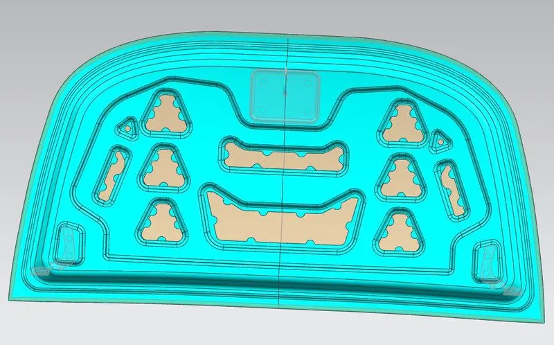
(Final Inner panel with hinge and striker mounting)
- Now we can thicken the inner surface in upwards direction for 0.75mm.
- Outer Panel:
Outer Panel is designed using the Styling surface and then adding hems for joining with the inner panel. The hem relief must be provided in corners for reducing stress concentrations. The following steps are involved in designing of the inner panel:
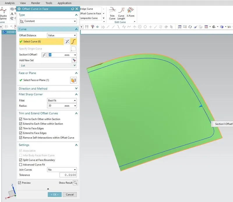
(Offset curve in face for outer panel)
A. Creation of Hems:
- Hem is created by offsetting the outer surface to 2.75mm as per the master section and creating an offset of 6mm in surface of the offset surface.
- The Sketch is used to trim the inside surface of the offset.
- Using another offset in plane, create an offset of 0.1mm, this is done for 3 face blend.
- Make a law extension in the direction of the outer panel surface, make sure it cuts the outer panel.
- Use face blend with the condition of 3 face blend to create hem radius.
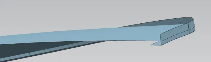
(Trimmed face and law extension for creation of hem)
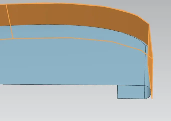
(Hem created using 3 face blend)
B. Hem Reliefs:
- Make curve in surface for hem relief. Minimum distance of the curve and edge of hem is 3mm.
- Use G1 (Tangential continuity) for start and end of the sketch.
- Trim the outer panel with the curve.
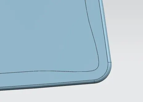
(Edge relief provided in the corners of the hem for reducing stress concentration)
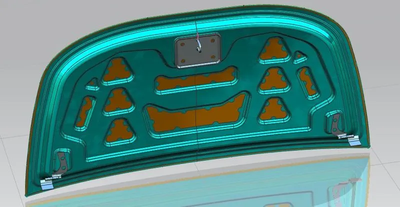
(Final Assembly with inner panel, outer panel, striker and the hinge assembly with correct assembly constraints)
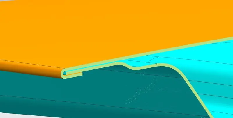
(Clip Section of the assembly showing correct position of the outer and inner panel)
- Now we can thicken the outer surface in downwards direction for 0.75mm.
- Check if the outer panel is evenly encircling the inner panel, if the inner panel is obstructing the outer panel, make a curve offset in the surface for 1-2mm and trim the outer area of the inner panel.
(final Assembly rendered)