Wiring harness routing & packaging Rules Week 3 Challenge
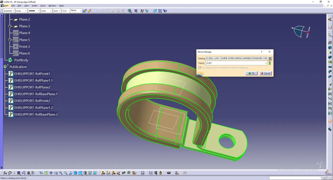
1. Defining the P-Clamp as Electrical support Part:
- The P Clamp IGS file is downloaded and saved as CATPART.
- The points for entry and exit for both side are made using arc/circle/ellipse centre.
- Plane coincident to the end face and passing through the points is created.
- A base plane is created taking offset of the perpendicular of the entry and exit planes.
- Now electric part design wokbench is opened.
- The P Clamp is defined as a support.
- The entry point and plane, exit plane and the base plane is defined for one entry point.
- This step is repeated as the p clamp is bi directional so it can have both entry and exit planes as one.
- The P-Clamp is added into the clamp catalog.
2. Defining Back Shell as Electric Device
- The back shell STP part is downloaded from the website and saved as a CATPART.
- The bundle entry point and the back shell connection point is defined.
- An axis system is created from the back shell connection point.
- While creating the axis system it is kept in mind that the y axis is perpendicular to the connecting face.
- The back shell is then defined usng the define back shell tool.
- After defining the back shell, it is added into the back shell catalog.
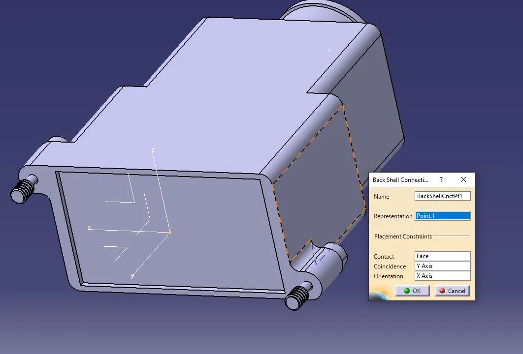
(defining bac shell connection)
3. Creating COT Tubes
- A part named COT 15mm is created in CATIA.
- Electric design workbench is opened and define protection part tool is used to create corrugated tube.
- The ID and thicness of the tube is proided.
- The best practice to define the bend radius is BR=1.5*OD. Using this the bend radus is also provided.
- The COT tube is then saved and added to the SLIT COT catalog family.
- This is done for all sizes of COT tubes.
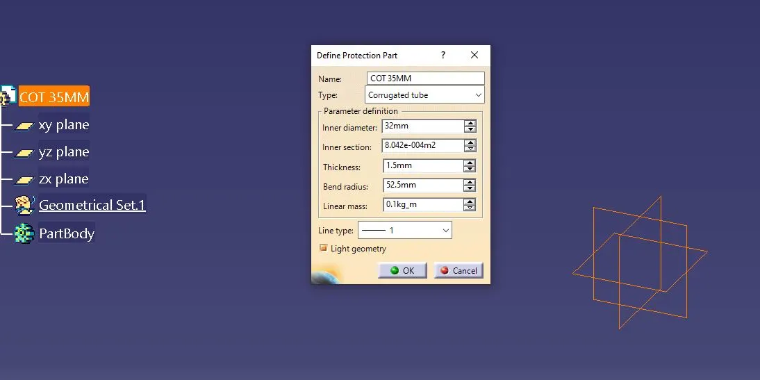
(defining COT tube)
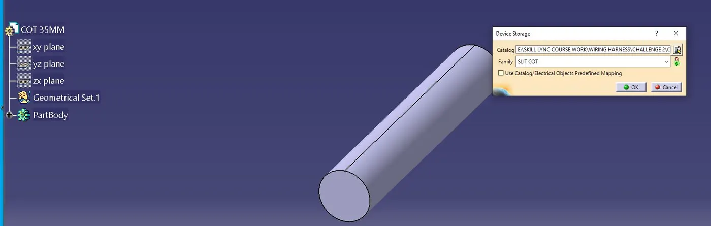
(Adding COT tube to catalog)