Week 1:- Introduction to BiW and Fixtures Challenge
Q1- What is BIW and define its parts?
It is a stage in automobile design or automobile manufacturing where all the sheet metal component are assembled by means of welding, revieting, bolting etc. is called Body in white (B.I.W), moving parts such as Door, Hood, Trunk Lid, Front Fender, and the components (chassis, motor) and trim (windshields, seats, upholstery, electronics, etc.) are added in a later stage.
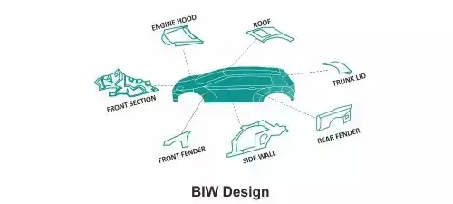
There are two types of BIW
1-Frame mounted on body structure.
2-Monocoqe body structure.
1) Frame mounted on body structure.
- It is also called as body on frame contruction.
- In this type body is mounted on the rigid frame
- Powertrains and suspension are mounted on the chasis.
- Used in utility vehicle, truck and buses.
2) Monocoqe body structure.
- It is also called as Chassis in built in body.
- It is not mounted on the top of anything therefore lower center of gravity hence better stability.
NOTE
- BIW accounts 50% weight of vehicle and we can consider this area to reduce the overall weight of the vehicle by using lighter materials and better structure.
- We mostly use steel in BIW industry becuse of easiness in fabrication, but in recent years fuel prices are increasing and in order to reduce the fuel consumption rate ,it becomes need to reduce weight of vehicle.
Materials commonly used in BIW industry
Steel
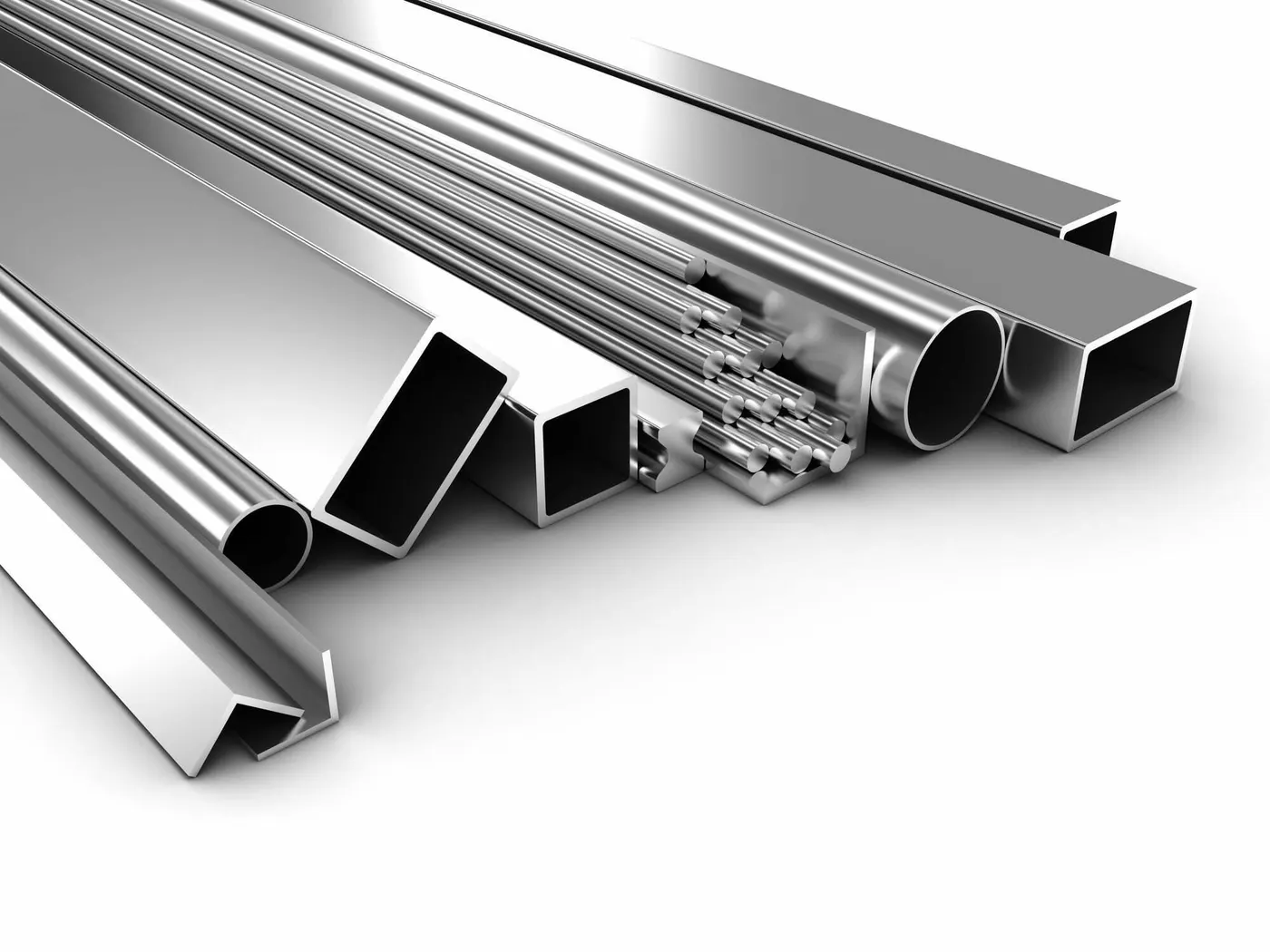
- We manfacture parts generally by stamping operations.
- Reinforcements are required to provide extra strength in critical structure.
- Parts made up of this material is having uniform thickness.
- Heavier in weight and more number of components.
Aluminium
- We manufacture parts generally by casting operations.
- Here as per our requirement we can increase the thickness of our part as casting gives you the room to vary the thickness as per our wish.
- Part made up of that material are lighter in weight and assembly required less number of component
CFRP (Carbon fiber reinforced plastics)
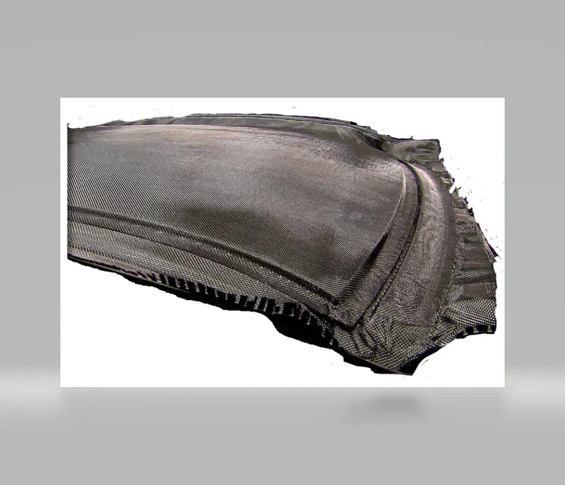
- It has low investment costs
- This material offer you to give increased design flexibility.
- Life of the component made up of this material is high
- We use non traditional machining for the manufacture of this component.
BIW NOMENCLATURE
We name the components of the car based on the U.K and U.S description.
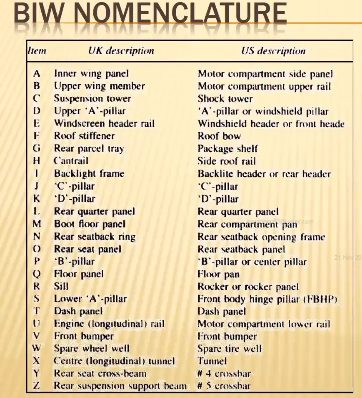
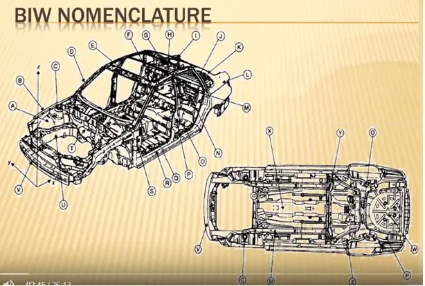
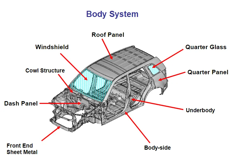
BIW parts consists of
1) Under body system.
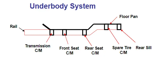
It consists of Frame/rail and cross member
- Frame/rail is the main structure and it is used for transferring the load of the engine and suspension.
- It is used for absorbing energy during frontal crash.
- It also support front and rear bumper.
Cross member
It is used to support transmission, Front and rear seats.
2) Body side system.
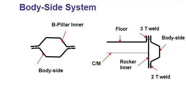
It consists of Pillars, roof rail and rocker
Pillars
- Pillars are responsible for protecting against roof crush and also they support the roof.
- they also required for the assembly of the door.
- A piller must satisfy the front visibility criteria.
Roof rail and Rocker
- They are much needed to complete the framing.
- They provide stiffness to the floor and the roof.
3) Front end system.
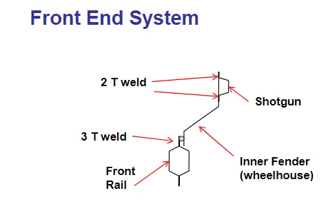
It consists of Shot gun and radiator support
Shot gun
- It transfer shock loads from the shock towers to the body.
- It absorbs part of crash energy.
- It supports battery and other parts.
Radiator support
- Support radiator.
4) Dash and cowl system.
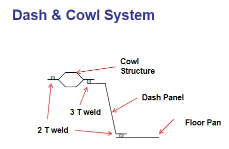
Dash panel
It support accelerator, brake and clutch pedals.
Cowl system
It supports windshield and wiper motor.
It provide stiffness to the body.
5) Roof system.
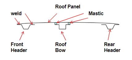
Roof outer panel
It is a panel used to protect us from harsh environment conditions.
Roof inner panel
It is used to provide stiffness to the outer panel
6) Closure system.
It consists of Hood and trunk lid.
Hood
It is a component which is used to access the engine compartment.
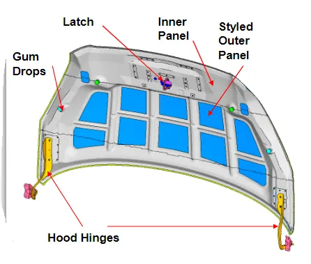
Trunk lid
It is a component used to access the rear compartment of the vehicle.

What is Fixtures and it's type
Fixture is a device which is used to hold, locate and support the component.
It is used to provide the stability to the part when any process is being done on that part. That process can be welding, riveting, grinding, drilling etc. In BIW fixture design Fixture works on 3-2-1 principle.
Here Fixture does not guide the tool.
3-2-1 Principle
Basically 3-2-1 principle is used to lock all 12 degree of freedom ( 6 translational (+ , -) and 6 rotational (cw, ccw)).
The 3-2-1 principle is a Component holding principle where three pins are located on the 1st principle plane, i.e. either XY, YZ, ZX. And two pins are located on the 2nd plane which is perpendicular to the 1st plane, and at last one pin on the plane which is mutually perpendicular to the 1st and 2nd planes.By using this method Componet can be arrested in all 12 degrees of freedom.
Types of fixtures
- Turning fixtures.
- Milling fixtures.
- Broaching fixtures.
- Grinding fixtures.
- Boring fixtures.
- Indexing fixtures.
- Tapping fixtures.
- Duplex fixtures.
- Welding fixtures.
- Assembly fixtures.
NOTE: Fixtures are named based on the type of machining operation for which they are designed and employed.
1-Turning fixtures
It is easy-to-hold regular workpieces on lathes in standard job holding devices like chucks and collets, between the centre and on mandrels or faceplates. But irregularly shaped components offer a lot of difficulties in holding them correctly.
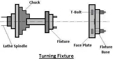
Simple odd shaped jobs can be held in chuck also, say by proper adjustment of jaws in a four-jaw chuck or by using shaped soft jaws. However, workpieces having complicated shaped have to be necessarily held in position with the help of turning fixtures. These fixtures are normally mounted on the nose of the machine spindle or on a faceplate and the workpieces held them.
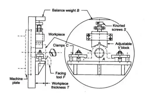
- Whenever necessary, the fixture must be provided with a counterweight so that to balance the unbalance fixture.
- These fixtures should be rigid enough
- They should have with minimum overhang.
- They should be designed to grip the workpieces very firmly
- They should not carry any dangerous projections for the machine operator or tool or both
- They should be able to provide proper support to thin and weak sections of the workpieces during the operation.
2-Milling fixtures
These fixtures are used on milling for carrying out different milling operations on the workpiece. The fixture is properly located on the table of the machine and secured in position by means of bolts and nuts.
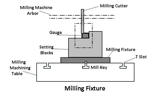
The table is shifted and set in the proper position, in relation to the cutter. The workpieces are located no the base of the fixture and clamped before starting the operation.
Since the cutting forces involved are quite high, and also intermittent, the clamping elements. Proper locating of the fixture on the machine table is usually achieved with the help of two tenons provided under the fixture base. These tenons enter a T-slot of the table to provide the required location. The fixture base can then be secured to the table by means of T-bolts and nuts.
3-Broaching Fixtures
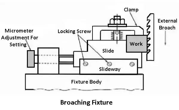
These fixtures are used on different types of broaching machines to locate, hold, and support the workpieces during the operations, such as keyway broaching operations, such as keyway broaching, hole broaching, etc. The use of a clamping plate as a fixture for internal pull-type hole broaching.
4-Grinding Fixture
Several different forms of fixtures are used in grinding machines to locate, hold, and support the workpieces during the operations. These fixtures may be the standard work-holding devices, such as chucks, mandrels, chuck with shaped jaws, magnetic chucks, etc.
For example; a vertical surface grinder with a rotary table will normally have a rotary fixture secured to its table. Similarly, a plain or string fixture may be provided on a surface grinder with the reciprocating table. A drill grinding attachment is a glaring example of a standard fixture used for grinding of drill geometry.
Whatever be the types of fixture designed for grinding operation, it should have provisions for supply and exit of coolant, mounting of wheel dressers and should be properly balanced, if it is a rotating fixture.
Boring Fixture
The operation can be performed in one of the following two ways:
- By keeping the boring bar (tool) stationary and feeding the touting workpiece on to the bar.
- By keeping the workpiece stationary and feeding the rotating boring bar into the work.
Accordingly, therefore, the boring fixture is made in two common designs.
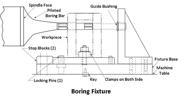
One of these incorporates the principle of a drilling jig, and in this, the boring bar (tool) is guided through a pilot bush. such fixture is also often referred to as boring jigs. the other design facilitates holding of the workpiece incorrect position, relative to the boring bar.
Although this fixture incorporates almost all the common principles of jig and fixture design, their construction need not be as sturdy as that of the milling fixtures, because they never have to bear as heavy cutting loads as involved in milling fixtures, because they never have to bear as heavy cutting loads as involved in milling operations.
Indexing Fixture
Several components need machining on the different surface such that their machined surface surfaces or forms are evenly spaced.
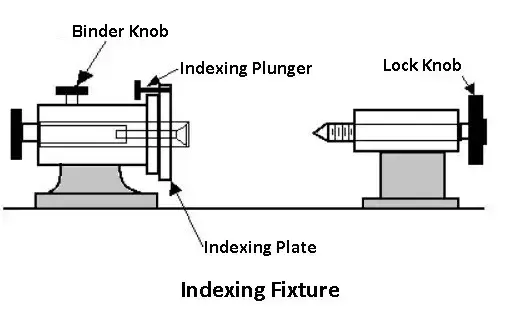
Such components are required to be indexed equally as many as the number of surfaces to be machined. Obviously, the holding devices (jigs or fixtures) used are made to carry a suitable indexing mechanism. A fixture carrying such a device is known as an indexing fixture.
Tapping Fixture
Tapping fixture is specially designed to position and firmly secure identical workpieces for cutting internal threads in drilled holes in them. Odd shaped and unbalanced components will always need the use of such fixtures, especially when the tapping operation is to be carried out repeatedly on a mass scale on such components.
Duplex Fixtures
It is the name given to the fixture which holds two similar components simultaneously and facilitates simultaneously machining of these components at two separate stations. While one workpiece is machined at one station.

Both the operations according to the requirement may be similar or different. Once machining at both the stations is over, the fixture is indexed through 180 degrees so that the first component is shifted to the second station for the second operation and the finished component to the first station.
The finished component is then uploaded here, replaced by a fresh component and the first operation performed on it. The cycle goes on repeating, which enables mass production of components at a fairly high speed.
Welding Fixtures
Welding fixtures are carefully designed to hold and support the various components to be welded in proper locations and prevent distortions in welded structures. For this, the locating element need to be careful, clamping has to be light but firm, placement of clamping elements has to be clear of the welding area. The fixture has to be quite stable and rigid to withstand the welding stresses.
In many cases, a preferably and commonly used practice is to first tack weld the structure by holding it in welding jig and then transfer it to a holding fixture for full welding. This helps in reducing the chances of distortion considerably and the fixture is subjected to lesser stresses.
Assembly Fixture
The function of these fixtures is to hold different components together in their proper relative position at the time of assembling them. For example, two or more steel plates can be held together in relative positions and riveted.
These fixtures, which are used for holding the components for performing mechanical operations, are known as mechanical assembly fixtures. Against this, there are other types of fixtures which the components are held for joining, such as the welding fixtures are also assembly fixtures, but for hot joining.
Difference Between Jigs and Fixtures
Following are the fundamental difference between a fixture and jig:
- A fixture holds and position the work but does not guide the tool, whereas a jig holds, locates and as well as guide the tool.
- The fixtures are heavier in construction and are bolted rigidly on the machine table, whereas the jigs are made lighter for quicker handling and clamping with the table is often unnecessary.
- The fixtures are employed for holding work in milling, grinding, planing or turning operations, whereas the jigs are used for holding the work and guiding the tool, particularly in drilling reaming or tapping operations.
Advantages of using jigs and fixtures in mass production work.
The following are the advantages of jigs and fixtures in mass production work.
- Eliminates the making out, measuring, and other setting methods before machining.
- It increases the machining accuracy because the workpiece is automatically located and the tool is guided without making any manual adjustment.
- It enables the production of identical parts which are interchangeable. This facilitates the assembly operation.
- It increases the production capacity by enabling a number of workpieces to be machined in the single set up, and in some cases, a number of tools may be made to operate simultaneously. The handling time is also greatly reduced due to the quick setting and locating of the work. The speed, feed and depth of cut for machining can be increased due to high clamping rigidity of jigs and fixtures.
- It reduces the operator’s labour and consequent fatigue as the handling operations are minimised and simplified.
- It enables a semi-skilled operator to perform the operations as the setting operation of the tool and the work is mechanised. This saves labour costs.
- It reduces the expenditure on the quality control of the finish products.
- It reduces the overall cost of machining by fully or partly automating the processes.
Applications of fixtures are:
- Drilling.
- Reaming.
- Tapping.
Basic Principle of fixture design
LOCATING POINTS: Locating the work is a prime necessity and requires suitable facilities. The correct setup ensures smooth insertion of a workpiece in the proper position and removing a workpiece from a jig without operational hassles or time consumption. The workpiece position needs to be precise with the guiding tool in the jig or setup pieces in the fixture.
FOOLPROOF: A foolproof design of jigs and fixtures does not permit a tool or workpiece to be placed in any other way other than the intended one.
REDUCTION OF IDLE TIME: Jigs and Fixtures must be designed in such a way that ensures smooth loading, clamping, machining, and unloading of a workpiece.
WEIGHT OF JIGS AND FIXTURES: A jig and fixture must be compact, easy to handle, and low cost regarding the number of materials used without giving up stiffness and rigidity.
MATERIALS FOR JIGS AND FIXTURES: Jigs and Fixtures are usually created with hardened materials to resist wear & tear and avoid frequent damage—for example, Mild steel, Cast iron, Die steel, High-speed steel, Caesium.
CLAMPING DEVICE: A suitable clamp is rated for its strength. It should be able to hold a workpiece firmly in its position while bearing the strain of the cutting tool simultaneously, without springing.
Broad rules of Jigs & Fixtures Design
- Compare the production cost of work between the existing tools and the tool to be made and see if the manufacturing price is not more than the expected gain.
- Determine location points and outline clamping arrangement.
- Make sure the clamping and binding pieces are as quick to act & efficient as possible.
- Make the jig and fixture foolproof.
- Make sure the locating points are adjustable.
- Do avoid intricate clamping arrangements.
- Round all corners.
- Make sure the operator has handles to make handling tasks easier.
- Provide ample amount of clearance.
- Provide holes for chips to escape.
- Systematically locate clamps to resist the pressure of the cutting tool while machining.
- To avoid springing action, place all clamps in proximity opposite to the bearing point of the workpiece.
- Test the jigs before putting them in a shop.
The 3-2-1 principle
Locating a part to be machined involves mainly three steps: Supporting, Positioning, and Clamping.
Two main intentions when placing a job on a jig/fixture are:
- Precisely positioning the part at the desired coordinates.
- Curbing all six degrees of movement so that the part cannot budge.
An extensively used method for obtaining these objectives is the 3-2-1 principle or six degrees of freedom for part location.
The 3-2-1 method is a work-holding principle where three pins are located on the 1st principle plane, i.e., either XY, YZ, ZX. And two pins are located on the 2nd plane perpendicular to the 1st plane, and at last, one pin on the plane is mutually perpendicular to the 1st and 2nd planes. The aim is to constrain the movement of the workpiece along all three axes.
Design objectives of Jigs and Fixtures
Before sitting down to design jigs/fixtures, the designer must consider the following points:
- The tool must be foolproof to prevent any mishandling or accidental usage by the operator.
- Easy to operate for increasing efficiency.
- Easy to manufacture using the lowest costs.
- Its ability to weather the tool life instead of appropriate materials.
- Must be consistent at producing high-quality parts.
- Must be safe and secure to use.
The designer must know the basics of the process and the tools associated with it for which the jig/fixture is designed. Overall objectives to look out for a while developing such tools are:
- Cycle time.
- Type of Jig/Fixture.
- Part Assembly sequence or Machining locations.
- Joining or machining process.
- Clamping method and clamping sequence.
- Required output accuracy.
- Type of equipment to be used with the jig.
- Method of ejecting finished output and transferring it to the next. Platform, whether the manual or automatic mode.
- The type of material, recommended weight, number of spots involving welding.
Assembly Line :
An assembly line is a process in which car panel/car body parts are joined as the semi finished assembly moves from one station to another station until the final product is produced.
In the process of joining in assembly line , panels are moved from one section to another sections.Those sections are called Station.
In BIW fixture designing we have various stations which are used to locate the panels so that joining processes can be done.
Some of these stations are:
- Geo Station
- Respot Station
- Pedestal Weld/Rivet
- Loading Station
- Buffer Station
- Marriage station
- Sealing station
- Curing station
1. Geo station:
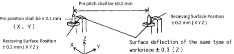
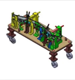
In this station geometry of two parts are fixed. it can be either using welding or riveting . In this station precision and geomatry of the finished product is defined Locating pins have closer tolerence of 0/-0.15.
Suppose the hole dia of panel is 16mm then the pin dia minimum can be 15.85.
Diameter of locating pins should be lesser than the panel hole dia. So Tolrence in locating pin is given in negative value.
2. Respot Station :
Once product comes out of the Geo Station and there are left out spots where spot welding or riveting is to be done. then it is moved to another station , that station is called Re-spot station.
These left out spots may be the due to clamp plan, cycle time,robot reach ability or any other various reasons.
In this station pins ahve tolrence upto 0/-0.28.
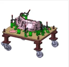
3. Pedestal Station :
In this station , Pedestal gun is mounted on a tool and panel is manipulated manually or by robot to weld the panels.
Pedestal station is generally a Re spot station.
Re spot station and Pedestal station, both perform same kind of operation . but to decide whether to go for pedestal or a re-spot station some parameters needs to consider like cycle time, floor space, no. of welds, clamp plan, or size of the panel.
4. Loading Station :
This station is used for loading of panel and same station is used to change the orientation of the if it is required in the upcomin station.
Sometime this station is used when Robots are unable to transfer panel from one station to another.
This station is used to make the balance between the process.
Some stations carry out procees in lesser time as compared to their respective stations.In that case panels can be stored in one sation so that assembly line process remains smooth.
6. Sealer Station :
In this station Sealant application is carried out.This process can be carried out manually or by using robots. Sealer is used in between two panels so that panels do not flatter due to friction.
7. Marriage Station :
In this Station inner and outer panels are joined. In this station to avoid the imprssion on the outer panel(A class surface), copper strips are used in betweenn the weld tip and A-class surface.
8. Curing Station :
In this Station product recieved after sealing application, is kept idle at ambient temperature, which allows sealent to get dry with better bonding between the panel.
- It is a set of thin plates (2 mm, 1mm, 0.5 mm, 0.25mm) used to adjust the gap or used for a better fit.
- Shimming can be of thickness 5mm, 8mm, or 10mm. If there is no proper fitting between mylar and Panel due to manufacturing errors then this error can be removed using shims.
- Shims are placed in the carline position so that gap can be adjusted in the required direction like X, Y, or Z.
There are three types of shimming. These are one-way, two-way, and three-way shimming.
Number of shimming depends upon the NC (Numeric control) cut angle and PIN angle with the car line.
If NC cut is less than 15 deg then mylar will have one-way shimming.
If NC cut is more than 15 deg in one direction then mylar will have a 2-way direction shimming
If NC has more than 15 deg angle in two directions then mylar will have 3-way directional shimming.
But in the case of pins, this case is a bit different. If the pin is on the angle with respect to the carline and that angle is more is not more than 15 deg then the pin will have 2-way directional shimming, if Pin’s angle is more than 15 deg in any direction then 3 shimming will be used.
Mylar
It is a block that touches the panel and holds or clamps the panel. Mylars are always designed in CAR LINE. Mylar is also called NC (Numerically Controlled)Block. Mylars are mounted on any block or plate with Shimming, So that height of mylar can be adjusted accordingly at the assembly level. For ‘A’ class surfaces Nylon mylars are used. So that surface can be saved from scratches.
Shimming can be 1 directional, 2 directional, or 3 directional as per the NC cut.
Pin
Pins are used to locking the rotational movement of the panel. Generally there two types of Pins, one is Round Pin and another one is a Diamond pin. We use two and three-directional shimming for pins as per the angle of the pin w.r.t. the carline. In some cases, we use a collared pin, when the pin is supposed to support the panel as well. For this kind of pin, we provide 3 way shimming irrespective of pin angle to the carline.
Blade
The plate which connects Riser to the Clamp cylinder is named Blade. This plate plays an important role in building the unit. The plate can be of any shape. But we need to keep in mind that the plate should be as compact as possible.
L block
A plate shaped as L is called an L block. This part is used as a connection between mylar and Blade. Generally, L blocks are used to provide shimming. It is not necessary that L blocks are only used for shimming, its uses changes as per the requirements, At some places, it is used just to connect one part to another. Similar to the L block one more block is used which is in the shape of T. So this block is called a T Block.
Pin block
Pin Block is also called Pin Retainer. This block holds the pin and restricts the rotational motion of the pin. Pin Block can be either manufactured one or Standard.
Riser
The part which is mounted on the base plate and holds a clamp or pin cylinder on it, is called Riser. Riser can be Standard Part or manufactured part, it varies from project to project. A riser can be a Single part or welded part. Standard risers also have various shapes and sizes.
Weldment
Weldment is the assembly of two or more parts that are joined by welding. To make a weldment it is the thumb rule to have a 5 mm overlay on each other plates so that space can be provided for welding. A weldment can be of any size and any number of plates.