Week 9:- 2D Detailing Challenge
Q1- What are the drawing template?
Drawing templates are the files of frame and title blocks which convey the design information that are used to generate 2D drawing from 3D part.
Neat and detailed drawing templates convey more information from designer to manufacturer so we can avoid misunderstanding and make a very effective parts which saves time and money.
Drawing templates are change as per the comany standards
Drawing templates are provide by thw customer at the starting of the project, If not then we should finalize at starting of project.
Drawing templates has n number of information such as:
COMAPNY NAME
PROJECT NAME
SHEET SIZE
SHEET NUMBER
ANGLE OF PROJECTON
REVISION NUMBER / LATTER (IF ITS REVISION DRAWING)
SIGNATURE OR NAME OF DRAWN BY, CHECKED BY, RESPONSIBLE ENGINEER AND APPROVED BY
PARTS DETAIL
QUANTITY
ADDITIONAL NOTES (SURFACE FINISH, HEAT TREATMENT, MATERIAL DETAIL ETC.)
SCALE, DATE, UNIT OF MEASUREMENT.
*NOTE : Above points can vary as per company standards.
Q2- What do you understand by Angle of projection?
Angle of projection
The angle at which an observer draw an object to convert it from 3D to 2D plane such as real object image to a plane paper is known as angle og of projection.
This is such a type of drawing in which parallel projection is used for the preparation of the drawing of an object.
These lines are perpendicular to the plane.
In this drawing it is assumed that the object is at infinity.
The shape of an object is seen in actual size in such drawing.
A plane is an imaginary surface on which pictures are prepared imaginably then it is tranferred to the paper.
This plane is faced toward the object whose view is to be prepared.
Generally, three views of an object are prepared. These are top view, Front view and side view.
ORTHOGRAPHIC PROJECTION
An Orthographic projection is a 2-D representation of a 3-D object. The 2-D drawing represents different sides of an object.
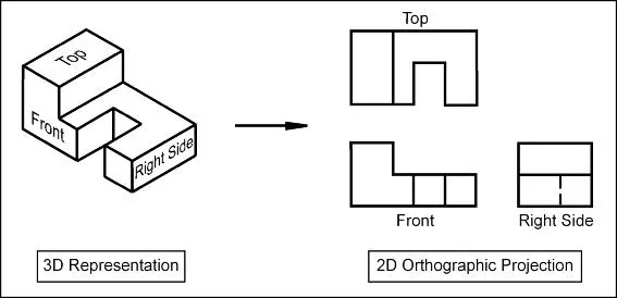
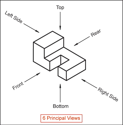
The six principal views
The 6 principal views are created by looking at the object (straight on) in the directions indicated.
Steps used to create an orthographic projection
The following steps take you through the creation of an orthographic projection.
- Choose a front view. This is the view that shows the most about the object.
- Decide how many views are needed to completely describe the object. If you are unable to determine which views will be needed, draw the standard views (front, top and right side).
- Draw the visible features of the front view.
- Draw projectors off of the front view horizontally and vertically in order to create the boundaries for the top and right side views.
- Draw the top view. Use the vertical projectors to fill in the visible and hidden features.
- Project from the top view back to the front view. Use the vertical projectors to fill in any missing visible or hidden features in the front view.
- Draw a 45° projector off of the upper right corner of the box that encloses the front view.
- From the top view, draw projectors over to the 45° line and down in order to create the boundaries of the right side view.
- Draw the right side view.
- Project back to the top and front view from the right side view as needed.
- Draw center lines where necessary.
Q4- What is the first angle and third angle projection ? and why can't we use the 2 nd and 4 th angle projection?
Third angle projection
Third angle projection can be visualized by “unfolding the box,” as if the object itself is being unfolded to show the views from each side. Figure 1 shows the views of a cube being represented by third angle projection.
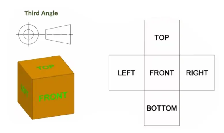
Third angle views are intuitive, as they represent you looking at the object from the corresponding side. The front view is always shown in the center. The view of the object from the right is shown to the right of the front view, the view of the object from the left is shown to the left of the front view, and the top and bottom views are shown above and below the front view, respectively. If we needed to show the view from the back, the back view would be placed below the bottom view.
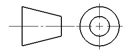
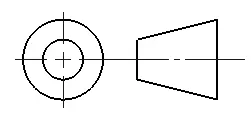
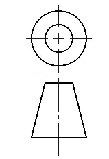
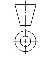
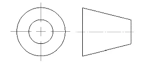
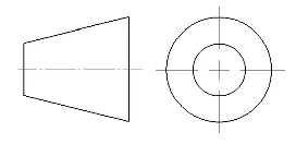
Quick Note on representation of the symbol for third angle. There are actually four ways Third Angle Projection can be represented on a print and all of them are acceptable (figure 2). The big takeaway here is it does not matter if the “side” view of the “cone” is on the right or left. For Third Angle Projection the “pointy” end of the side view of the cone in the symbol is always pointing towards the front/”circle” as shown in Figure 2 below. All four of these are perfectly acceptable for third angle:
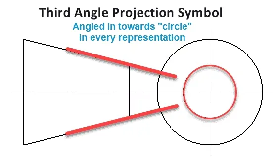
All orientations below are acceptable
First angle projection
First angle views are less intuitive. They can be visualized by “tipping the box over.” Figure 2 shows the views of a cube being represented by first angle projection.
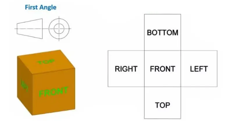
The front view is shown in the center, just like in the third angle projection. To place the view of the right side, you must tip the box so that the right side is facing you. To do this, the box must be tipped toward the left. This results in the right-side view of the object being located on the left side of the front view. With the front side facing you once more, tip the box to the right, and you will have the left side facing you. So, the left-side view will be located to the right of the front view. This same method is used for top and bottom views. With the front of the object facing you, tip the cube downward. You now have the top side facing you, with the top view being located under the front view on the drawing. By tipping the front view upward, the bottom view of the object is facing you, with the bottom view located above the front view.
Again there is common confusion about the symbol representation for First Angle Project. There are four ways First Angle Projection can be represented on a print and all of them are acceptable. The big takeaway here is it does not matter if the “side” view of the “cone” is on the right or left. For First Angle, the “pointy” end of the side view of the cone in the symbol is always pointing away from the front/”circle”
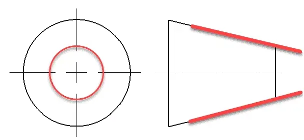
All the four orientations of first angle projection are possible.
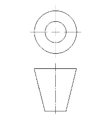
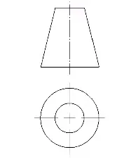
Reason behind not using second and fourth angle projection
Let us first understand the concept behind the angle projection system. Imagine you have Vertical Plane (VP) and Horizontal Plane (HP) (Perpendicular to each other),now we have 4 quadrants. For 1st angle projection system, we place object in 1st quadrant, for 2nd angle projection system, we place object in 2nd quadrant and so on.
In Second quadrant, Vertical plane (VP) lies in between object and observer. Therefore front view of the object will lie on vertical plane whereas top view will lie on horizontal plane. As per rule of projection when horizontal plane is rotated 90 degree in clockwise direction, top and front view will overlap.
Overlapping projection views create confusion in the drawing. Therefore 2nd angle projection system is not used.
To sum up, because of overlapping of front and top views 2nd and 4th angle projections are not used. First and third angle projection systems are recommended for orthographic projections.
Q5- What is GD&T? What are the benefits of GD&T?
It is compilation of symbols and rules that efficiently describe and control dimensioning & tolerancing for all drawings (castings, machined components,etc.). It is documented in ASMEY14.5M which has the symbols, rules, and simple examples. Also ASME Y14.8 has guidance for
casting and forging drawings.
Advantages of using GD&T
a. It is a simple and efficient method for describing the tolerancing mandated by the designer of the part.
b. It eliminates ambiguities as to what Datum features are to be contacted to establish the Datum planes and/or Datum axis that are to be used for locating other features. All inspection will result in the same result – the dimension is within or out of tolerance. Fig-a illustrates a simple example of ambiguities associated with the “old” type drawing. Fig-b illustrates the same example with GD&T.
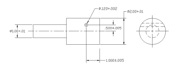
Fig-a
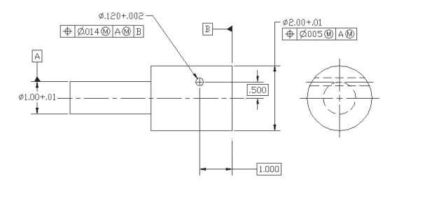
Fig-b
c. It simplifies inspection because hard gages can often be utilized and inspection fixtures are often mandated which simplifi es inspection for production quantities.
d. It forces the designer to totally consider function, manufacturing process, and inspection methods. The result is larger tolerances that guarantee function, but reduce manufacturing & inspection costs. Also the “bonus” or extra tolerance for certain conditions can result in significant production cost savings.
In addition the time to analyze whether a missed dimension is acceptable is dramatically reduced.
Q6- Explain all the symbols used in GD&T?
a) Form tolerances
Form tolerance is a basic geometric tolerance that determines the form of the target (part). None of the characteristics of form tolerance require a datum—forms can be independently determined.It is of four types.
Straightness
The straightness requirement specifies how perfectly straight a target should be. It is applied to lines and not planes, and represents a curve in the center line or generatrix. Therefore, straightness is used to indicate the warpage tolerance of long objects.
Flatness
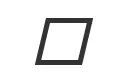
The flatness requirement specifies the evenness of a surface, or how accurately flat a target plane should be. The most protruding part and the most concaved part must be at a specific distance between two planes that are separated vertically.
Circularity / Roundness

The roundness requirement specifies how perfectly circular a target—the circular cross-section of a shaft, bore, or cone—should be.
Cylindricity

The cylindricity requirement specifies how accurately circular and straight a target cylinder is. The value represents any distortion in a cylinder.
b) Profile tolerances
Profile tolerance defines a uniform boundary around a surface within which the elements of the surface must lie. Profile is a complex tolerance that simultaneously controls a feature's form, size, orientation, and sometimes location.
Profile of a surface
Controls size and form of a feature. In addition it controls the location and orientation where the datum reference frame is used.
Profile of a line
Similar to profile of a surface applies to cross sections of a feature.
c) Orientation
Perpendicularity.
Control the orientation of the feature which is nominally perpendicular to the primary datum of its datum reference frame.
Angularity.
Control the orientation of the feature at a specific angle in relation to the primary datum of its datum reference frame.
Parallelism.
Control the orientation of the feature which is nominally parallel to the primary datum reference frame.
d) Location
Position.
Control the location and orientation of the feature in relation to its datum reference frame.
Concentricity.
Controls the concentricity of a surface of revolution to a central datum.
Symmetry.
Controls the symmetry of two surfaces about the central datum.
e) Runout
Circular runout.
Controls circularity and coaxiality of each circular segment of a surface independently about the coaxial datum.
Total runout.
Control circularity, straightness coaxiality and taper of a cylindrical surface about the coaxial datum.