Advanced Sheet Metal Design Using NX Cad Challenge_3_Dimple Using solid punch
AIM: To create the dimple using solid punch command.
THEORY OF PUNCH AND DIE
Sheet metal forming is the cold forming process in which there is the permanent deformation of the sheet takes place in order to create the complex geometry feature.The process is carried out in the plane of sheet by tensile forces with high ratio of surface area to thickness ratio.
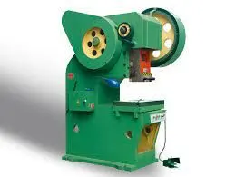
PRESS
A press is the machine used for performing most of the cold forming operations, it consists of
- Rigid machine frame.
- Press tools.
- Ram.
- Power source and mechanisms.
- Die assembly.
- Press accessories.
DIE
It is the element in the press which is use to hold the sheet metal we have to provide the clearance on the die for the Punching operation.The Die corresponds in size and shape to the Punch and is secured directly beneath the Punch
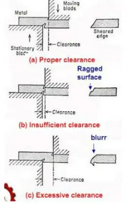
Why we need to provide optimum clearance?
A narrow strip of metal is severely plastically deformed to the point where it fractures at the surfaces in contact with the blades
the fractures then propagate in the inward direction to provide the complete separations.
CLEARANCE VALUE: (2-10)% OF THICKNESS
- PROPER CLEARANCE - CLEAN FRACTURE SURFACE
- INSUFFICIENT CLEARANCE - RAGGED FRACTURE SURFACE
- EXCESSIVE CLEARANCE - GREATER DISTORTION, GREATER ENERGY REQUIRED TO SEPARATE METAL.
Why we need to provide optimum clearance?
A narrow strip of metal is severely plastically deformed to the point where it fractures at the surfaces in contact with the blades
the fractures then propagate in the inward direction to provide the complete separations.
CLEARANCE VALUE: (2-10)% OF THICKNESS
- PROPER CLEARANCE - CLEAN FRACTURE SURFACE
- INSUFFICIENT CLEARANCE - RAGGED FRACTURE SURFACE
- EXCESSIVE CLEARANCE - GREATER DISTORTION, GREATER ENERGY REQUIRED TO SEPARATE METAL.
-
PUNCH
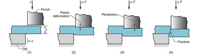
The punch operation detach the metal pieces by causing the fracture of the material Unlike, the cutting action of a drill or holesaw will generate large amounts of scrap leaving the work area covered in sharp scrap and chipping. The action of a Punch & Die uses a solid metal piece, the “Punch” located vertically above the “Die”. The Punch is usually, hydraulically driven to meet the Die. The location and alignment of the Die is critical, with the material to be punched in between.
There are 3 phases for a Punch & Die action;
- Deformation
- Penetration
- Fracture
Cutting force F = S*T*L
S= ULTIMATE SHEAR STRENGTH OF THE MATERIAL.
T = THICKNESS OF MATERIAL.
L = CIRCUMFERENCE OF PUNCH.
DESIGN FLOWCHART
- TAB.
- EXTRUDE.
- SOLID PUNCH.
- CHANGE THE DIMPLE SHAPE.
- PATTERN FEATURE.
STEP BY STEP PROCEDURE
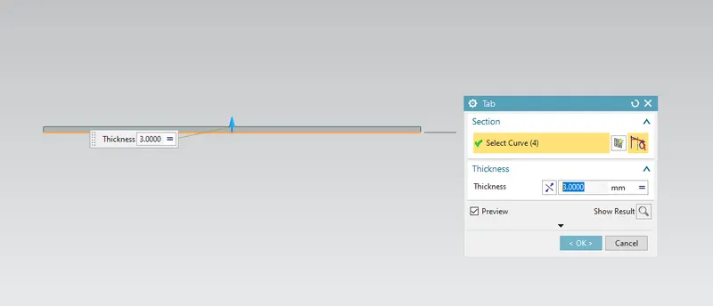
1- CREATE THE TAB OF GIVEN DIEMENSION
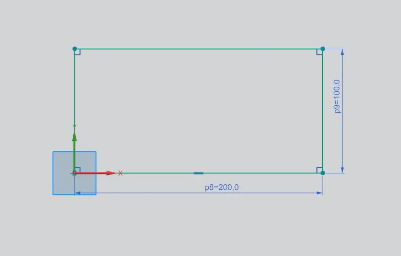
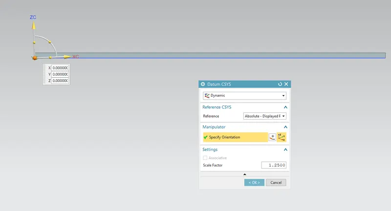
2- CREATE A NEW DATUM CSYS OF 3 DEG. INCLINATION WITH RESPECT TO THE X-AXIS.
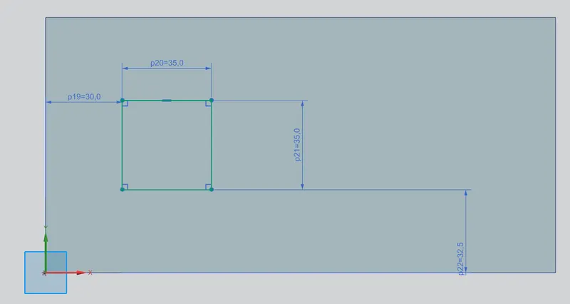
3- CREATE A SKETCH ON THE XY PLANE OF NEW DATUM CSYS ACCORDING TO THE DIEMENSION AS FOLLOWS
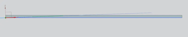
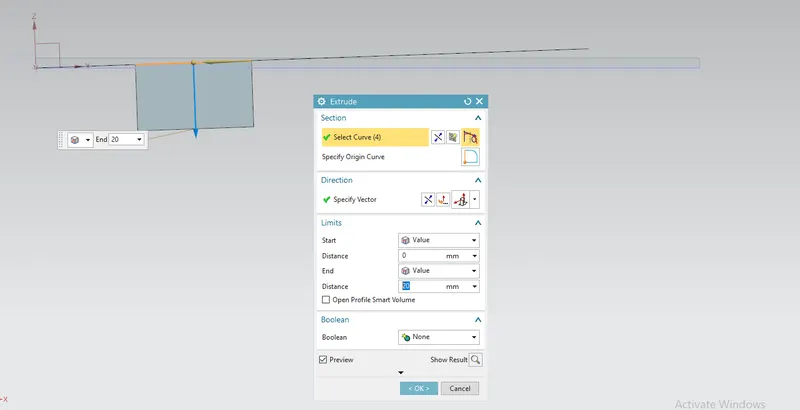
4- EXTRUDE THE NEW SKETCH TO THE DISTANCE OF 20mm AS SHOWN BELOW
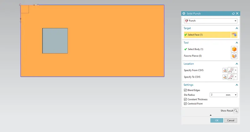
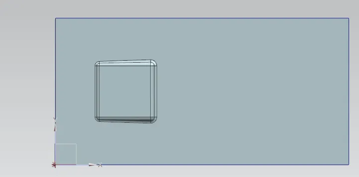
5- USE SOLID PUNCH COMMAND
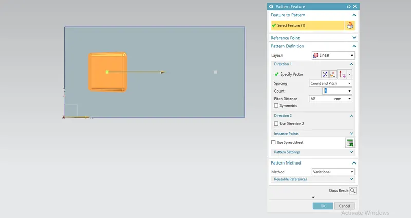
6- USE PATTERN FEATURE COMMAND TO CREATE THE COPY OF 2 OF THAT FEATURE ALONG THE LINE
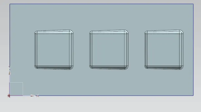
DIFFERENT VIEWS
- TOP
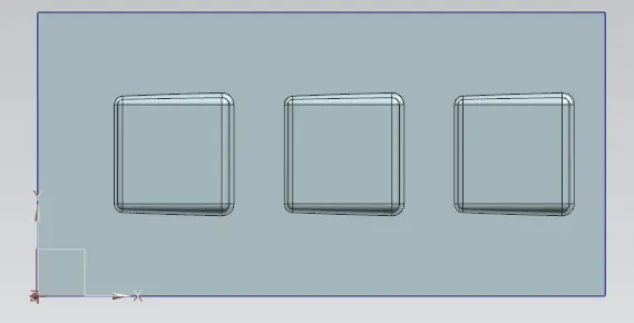
- FRONT

- RIGHT
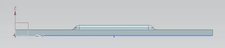
- LEFT

- TRIMETRIC
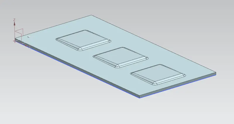
- BOTTOM
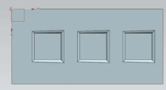
CONCLUSION : HERE WE GOT TO LEARN ABOUT THE PUNCH AND DIE AND WE SUCCESSFULLY COMPLETED THE DESIGN OF THE DIMPLE ON THE SHEET USING THE SOLID PUNCH COMMAND.