Week 2:- BiW Fixture Basics Challenge
1-PROCESS EXECUTION ACTIVITY
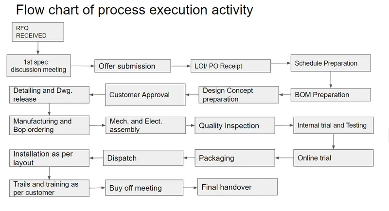
RFQ Received: A request for quote (RFQ), also known as an invitation for bid (IFB), is a process in which a company solicits select suppliers and contractors to submit price quotes and bids for the chance to fulfill certain tasks or projects.
1st spec discussion meeting: In this meeting customer requirement and specification is discussed also the timeline and overall budget of the project will be discussed.
Offer submission: Whatever decision we made in earlier stage is documented and final offer is proposed to the customer.
LOI/ PO Receipt: Aka letter of intent or purchase order, In this stage customer will review the offer proposed by us and compare it with different vendors and choose the best for themselves.
Schedule Preparation: Once customer accepted our offer we are going to set the schedule the various activities for the completion of project.
BOM Preparation: After clarify the activity we prepare the sheet for required resources needed for the project with their price and no.of quantities.
Design Concept preparation: Now we are going to do carryover study of our previous existing model and try to modify the part for better product once this study is over we present the model of final product to the customer.
Customer Approval: After customer sees the model and satisfied with the design he approved final design model and if it is not we have to modify the design as per the customer need.
Detailing and Dwg. release: After final approval by the customer we release the 2D detailing and drawing of the model for the manufacturing and we have to contact with the CAM TEAM.
Manufacturing and Bop ordering: In this stage we decide the most suitable manufacturing process to manufacture the model and what components required to purchase we handover the Bom to the market and sales team
Mech. and Elect. assembly: Here mechanical and elecrical component are assembled of the project.
Quality Inspection: After Assembly we check whether parts are assembled with in the tolerance limit.
Internal trial and Testing: Once inspection is done we ensure that whether the functioning of the project meeting our standard requirement or not.
Online trial: Here we demonstrate the working of the project to the customer.
Packaging: Finally we pack all the component carefully and send it to dispatch facility.
Dispatch: Here we dispatch the package to the customer address with the tracking Id.
Installation as per layout: After package reach to the customer we install the project to the customer location by sending special team.
Trails and training as per customer: then we trained the customer about how to operate and do's and don't of the project.
Buy off meeting: Here customer pays the deal amount to the Project management team also if customer wants the additional feature it is also considered by the project management team.
Final handover: Once customer demand is fullfilled we handover all the manuals along with the project to the customer.
Q2 WELDING PROCESSES
- Welding: permanent joining of two materials,usually metals, by coalescence.
- Coalescence results in atoms of the materials being joined to form common crystal structures.
- Coalescence induced by a combination of temperature, pressure and metallurgical conditions.
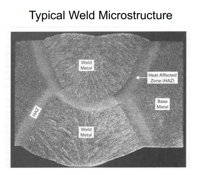

Joining Variations
Fastening: Materials are joined together using fasteners (e.g., screws, nails, nuts, bolts).
Advantages: Any shape or material; can be disassembled; often the least expensive method for volume production.
Disadvantages: Do not develop the full strength of the base material; do not produce hermetic seals; fasteners are extra parts; need to drill holes.
True bonding: Formation of a bond
- The perfect joint is indistinguishable from the material surrounding it (diffusion bonding).
- Any two solids will bond if surfaces are brought into intimate contact.
Two inhibiting factors:
1) Surface contamination (in nanoseconds).
2) Do not mate perfectly (true contact area <10%).
- Welding using interfacial shear (cold welding)
a) Ultrasonic welding.
b) Friction welding.
- Adhesive bonding:
a) Viscous fluid fills hills & valleys.
b) Bond created by surface tension forces or mechanical interlocking.
c) Weaker than interatomic bonds.
d) Best for joining sheets, fibers.
- Diffusion bonding: Materials held together under high pressure at elevated temperature to increase contact area (surface contaminants must be soluble).
- Fusion welding: Materials are melted and bonded together by means of heat (chemical or electrical).
Classification of welding processes
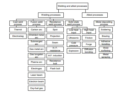
This approach of classifying the welding process is primarily based on the way metallic pieces are united together during welding such as
1- Availability and solidification of molten weld metal between components being joined are similar to that of casting: Cast weld process.
2- Fusion of faying surfaces for developing a weld: Fusion weld process.
3- Heating of metal only to plasticize then applying pressure to forge them together: Resistance weld process.
4-Use pressure to produce a weld joint in solid state only: Solid state weld process.
1-Cast welding process:
Those welding processes in which either molten weld metal is supplied from external source or melted and solidified at very low rate during solidification like castings
Types of cast welding process
a) Electroslag Welding: Weld metal is melted by electrical resistance heating and then it is allowed to cool very slowly for solidification similar to that of casting.
b) Thermite welding : Weld metal is melted externally using exothermic heat generated by chemical reactions and the melt is supplied between the components to be joined.
2-Fusion Weld Processes : Those welding processes in which faying surfaces of plates to be welded are brought to the molten state by applying heat and cooling rate experienced by weld metal in these processes are much higher than that of casting.
3-Resistance welding processes : Welding processes in which heat required for softening or partial melting of base metal is generated by electrical resistance heating followed by application of pressure for developing a weld joint.
4- Solid state welding process : Welding processes in which weld joint is developed mainly by application of pressure and heat through various mechanism such as mechanical interacting, large scale interfacial plastic deformation and diffusion etc.
Types of joint
Butt joint
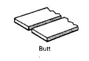
A butt joint or butt weld is a joint where two pieces of metal are placed together in the same plane, and the side of each metal is joined by welding.
Note: The area of the metal’s surface that is melted during the welding process is called the faying surface.The faying surface can be shaped before welding to increase the weld’s strength which is called edge preparation.The edge preparation may be the same on both members of the butt joint or each side can be shaped differently.
Reasons for preparing the faying surfaces for welding include the following:
- Codes and standards.
- Metals.
- Deeper weld penetration.
- Smooth appearance.
- Increased strength.
Lap joint
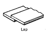
Lap welding joints are essentially a modified version of the butt joint. They are formed when two pieces of metal are placed in an overlapping pattern on top of each other. They are most commonly used to joint two pieces with differing thicknesses together. Welds can be made on one or both sides.
Lap joints are rarely used on thicker materials, and are commonly used for sheet metal. Potential drawbacks to this type of welding joint include lamellar tearing or corrosion due to overlapping materials. However, as with anything, this can be prevented by using correct technique and modifying variables as necessary.
Tee joint
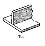
Tee welding joints are formed when two pieces intersect at a 90° angle. This results in the edges coming together in the center of a plate or component in a ‘T’ shape. Tee joints are considered to be a type of fillet weld, and they can also be formed when a tube or pipe is welded onto a base plate.
Tee joints are not usually prepared with groove, unless the base metal is thick and welding on both sides cannot withstand the load the joint must support. A common defect that occurs with tee joints is lamellar tearing—which happens due to restriction experienced by the joint. To prevent this, welders will often place a stopper to prevent joint deformities.
Corner joint
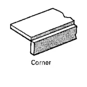
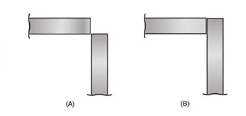
Corner joints have similarities to tee welding joints. However, the difference is the location of where the metal is positioned. In the tee joint, it’s placed in the middle, whereas corner joints meet in the ‘corner’ in either an open or closed manner—forming an ‘L’ shape.These types of joints are among some of the most common in the sheet metal industry, such as in the construction of frames, boxes and other applications.
There are two ways of fitting up an outside corner joint—either it forms a V-groove (as shown in fig.a) or forms a square butt joint (as shown in fig. b).
Edge joint
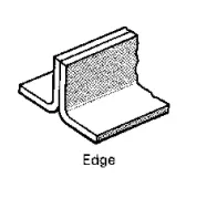
In an edge joint, the metal surfaces are placed together so that the edges are even. One or both plates may be formed by bending them at an angle.
3-RESISTANCE WELDING AND ITS APPLICATION IN AUTOMOTIVE SECTOR
Resistance welding
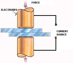
Resistance welding is the joining of metals by applying pressure and passing current for a length of time through the metal area which is to be joined. The key advantage of resistance welding is that no other materials are needed to create the bond, which makes this process extremely cost effective.
There are several different forms of resistance welding (e.g. spot and seam, projection, flash, and upset welding) which differ primarily by the types and shapes of weld electrodes that are used to apply the pressure and conduct the current.
The electrodes, typically manufactured from copper based alloys due to superior conductive properties, are cooled by water flowing through cavities inside the electrode and the other conductive tooling of the resistance welding machine.Resistance welding machines are designed and built for a wide range of automotive, aerospace and industrial applications. Through automation, the action of these machines is highly controlled and repeatable allowing manufacturers to staff production readily.
Types of resistance welding process
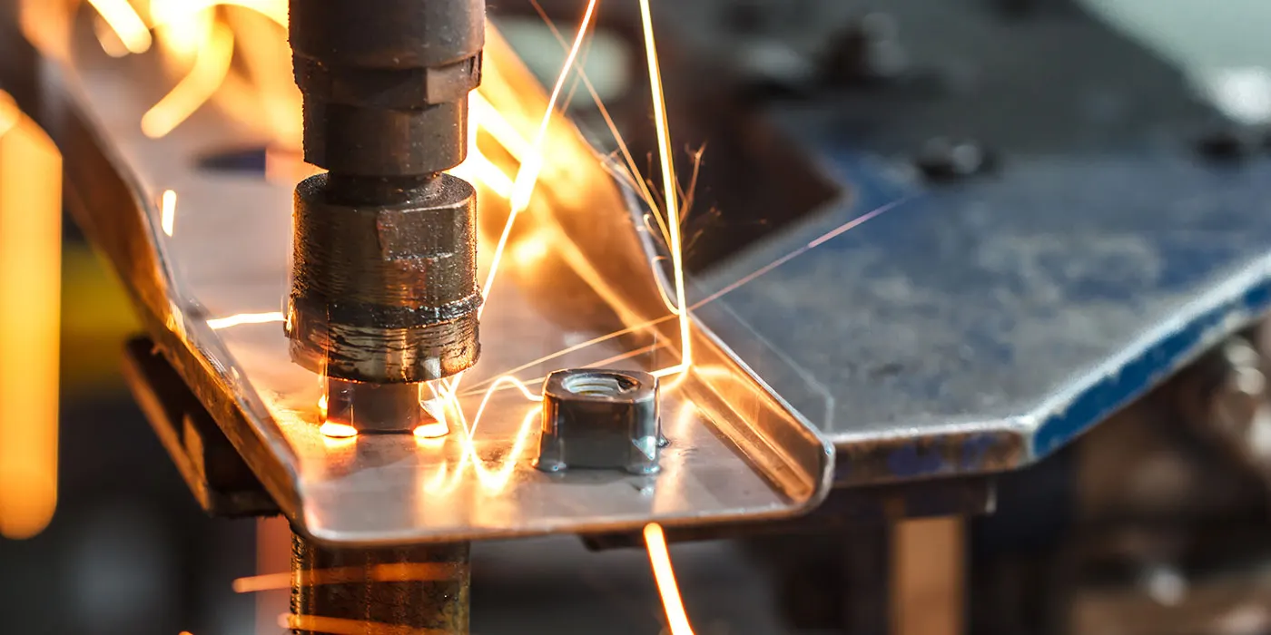
1- Spot Welding : Resistance Spot Welding, like all Resistance Welding Processes, creates welds using heat generated by resistance to the flow of welding current between the faying surfaces, as well as force to push the workpieces together, applied over a defined period of time. Resistance Spot Welding uses the face geometries of the welding electrodes themselves to focus the welding current at the desired weld location, as well as to apply force to the workpieces. Once sufficient resistance is generated, the materials set down and combine, and a weld nugget is formed.
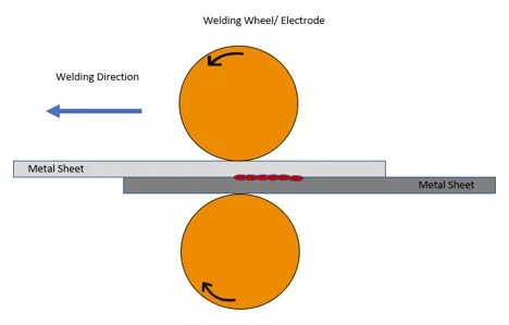
2-Seam welding : Resistance Seam Welding is a subset of Resistance Spot Welding using wheel-shaped electrodes to deliver force and welding current to the parts. The difference is that the workpiece rolls between the wheel-shaped electrodes while weld current is applied. Depending on the particular weld current and weld time settings, the welds created may be overlapping, forming a complete welded seam, or may simply be individual spot welds at defined intervals.
3-Projection Welding:
Like other Resistance Welding Processes, Projection Welding uses heat generated by resistance to the flow of welding current, as well as force to push the workpieces together, applied over a defined period of time. Projection Welding localizes the welds at predetermined points by using projections, embossments or intersections, all of which focus heat generation at the point of contact. Once the weld current generates sufficient resistance at the point of contact, the projections collapse, forming the weld nugget.
Solid Projections are often used when welding fasteners to parts. Embossments are often used when joining sheet or plate material. An example of Projection Welding using material Intersections is cross-wire welding. In this case the intersection of the wires themselves localizes heat generation, and therefore resistance. The wires set-down into one another, forming a weld nugget in the process.
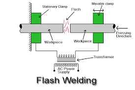
4-Flash Welding:
Like other Resistance Welding Processes, Flash Welding uses heat generated by resistance to the flow of welding current, as well as force to push the workpieces together, applied over a defined period of time. Flash Welding is a Resistance Welding Process which generates resistance using flashing action. This action is created using very high current density at very small contact points between the workpieces. At a predetermined point after the flashing process has begun, force is applied to the workpiece, and they are moved together at a controlled rate. Rapid upset created by this force expels oxides and impurities from the weld.
5-Upset welding:
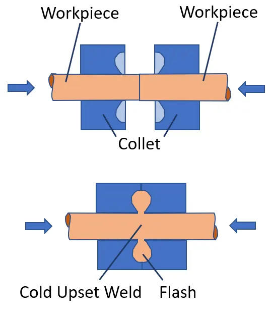
Like other Resistance Welding Processes, Upset Welding uses heat generated by resistance to the flow of welding current, as well as force to push the workpieces together, applied over a defined period of time. While similar to Flash Welding, in Upset Welding the workpieces are already in firm contact with one another, so no flashing occurs. Pressure is applied before the current is started, and is maintained until the process is complete.
| Spot welding | JOINING OF BIW COMPONENT |
| Seam welding | USED FOR LEAK PROOF JOINT |
| Projection welding |
Automotive. Projection welding is used to weld connectors such as screws, nuts, and bolts to flat sheets. |
| Flash welding |
(i) It is used for welding metal sheets, bars, rods fittings etc. (ii) Flash welding finds applications in automotive and air craft products. (iii) It is also employed in household appliances, refrigerators and farm implements. |
| Upset welding |
(i) This process is mainly used for welding nonferrous materials of smaller cross section such as bars, rods, wires, tubes etc.
|
4-FUSION WELDING, TYPES OF FUSION WELDING AND IT'S APPLICATION.
Fusion Weld Processes
Those welding processes in which faying surfaces of plates to be welded are brought to the molten state by applying heat and cooling rate experienced by weld metal in these processes are much higher than that of casting. The heat required for melting can be produced using electric arc, plasma, laser andelectron beam and combustion of fuel gases. Probably this is undisputed way of classifying few welding processes. Common fusion welding processes are given below:
Fusion Weld Processes.
1-Shielded metal arc welding.
2-Submerged arc welding.
3-Gas tungsten arc welding.
4-Plasma arc welding.
5-Metal inert gas welding.
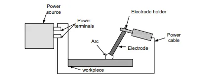
Fusion/arc welding process principle : All arc welding processes apply heat generated by an electric arc for melting the faying surfaces of the base metal to develop a weld joint.
1- Shielded Metal Arc Welding (SMAW)
In this process, the heat is generated by an electric arc between base metal and a consumable electrode. In this process electrode movement is manually controlled hence it is termed as manual metal arc welding. This process is extensively used for depositing weld metal because it is easy to deposit the molten weld metal at right place where it is required and it doesn’t need separate shielding. This process is commonly used for welding of the metals, which are comparatively less sensitive to the atmospheric gases.This process can use both AC and DC. The constant current DC power source is invariably used with all types of electrode (basic, rutile and cellulosic) irrespective of base metal (ferrous and non-ferrous). However, AC can be unsuitable for certain types of electrodes and base materials. Therefore, AC should be used in light of manufacturer’s recommendations for the electrode application. In case of DC welding, heat liberated at anode is generally greater than the arc column and cathode side. The amount of heat generated at the anode and cathode may differ appreciably depending upon the flux composition of coating, base metal, polarity and the nature of arc plasma. In case of DC welding, polarity determines the distribution of the heat generated at the cathode and anode and accordingly the melting rate of electrode and penetration into the base metal are affected.
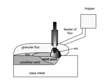
2- Submerged arc welding (SAW)
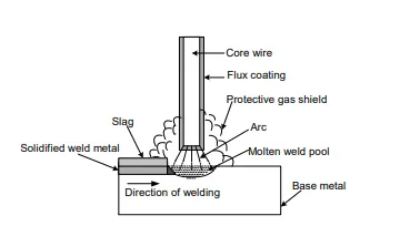
Submerged arc welding (SAW) process uses heat generated by an electric arc established between a bare consumable electrode wire and the work piece. Since in this process, welding arc and the weld pool are completely submerged under cover of granular fusible and molten flux therefore it is called so. During welding, granular flux is melted using heat generated by arc and forms cover of molten flux layer which in turn avoids spatter tendency and prevents accessibility of atmospheric gases to the arc zone and the weld pool. The molten flux reacts with the impurities in the molten weld metal to form slag which floats over the surface of the weld metal. Layer of slag over the molten weld metal results.
Increased protection of weld metal from atmospheric gas contamination and so improved properties of weld joint, Reduced cooling rate of weld metal and HAZ owing to shielding of the weld pool by molten flux and solidified slag in turn leads to
a) Smoother weld bead.
b) Reduced the cracking tendency of hardenable steel.
3- Gas Tungesten arc welding (G.T.A.W)
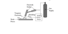
Tungsten inert gas welding process also called as gas tungsten arc welding is named so because it uses
a) Electrode primarily made of tungsten
b) Inert gas for shielding the weld pool to prevent its contamination from atmospheric gases especially when joining high strength reactive metals and alloys such as stainless steel, aluminium and magnesium alloys, wherever high quality weld joints need to be
developed for critical applications like nuclear reactors, aircraft etc.
Invention of this process in middle of twentieth century gave a big boost to fabricators of these reactive metals as none of the processes (SMAW and Gas welding) available at that time were able to weld them successfully primarily due to two limitations
a) contamination of weld from atmospheric gases
b) poor control over the heat input required for melting.
Moreover, welding of aluminium and its alloys with shielded metal arc welding process can be realized using halide flux coated electrodes by overcoming the problems associated with Al2O3, however, halides are very corrosive and therefore welding of aluminium is preferable carried out using inert shielding environment with the lerp of processes like GTAW and GMAW.Despite of so many developments in the field of welding.
TIG process is invariably recommended for joining of thin aluminium sheets of thickness less than 1mm.
4-Plasma arc welding (PAW)
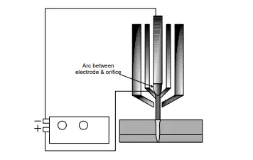
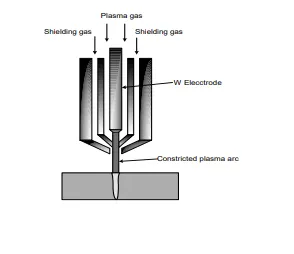
In plasma arc welding, arc is forced to pass through nozzle (water cooled copper) which causes the constriction of the arc Constriction of arc results in
(a) Reduction in cross-sectional area of arc.
(b) Increases energy density.
(c) Increases to velocity of plasma approaching to the sound velocity and temperature to about 25000 Degree celsius.
Above stated factors together make PAW, a high energy density and low heat input welding process therefore; it poses fewer which in turn reduces problems associated with weld thermal cycle.Energy density and penetration capability of plasma jet is determined by the various process parameters namely plasma current, nozzle orifice diameter and shape, plasma forming gas (Air, He, Ar) and flow rate of plasma carrying. Increasing plasma current, flow rate, thermal conductivity of plasma forming gas and reducing nozzle
orifice diameter increases together result in the energy density and penetration capability of plasma jet. In general, the plasma cutting uses high energy density in combination with high plasma velocity and high flow rate of high thermal conductivity plasma forming gas. A combination of such characteristics for plasma cutting is achieved by controlling above process parameters. Further, thermal conductivity of plasma forming gas must be high enough for cutting operation so that heat can be effectively transferred rapidly to the base metal. Plasma welding needs comparatively low energy density and low velocity plasma to avoid melt through or blowing away tendency of molten metal.
5- Metal inert gas welding (MIG)
This process is based on the principle of developing weld by melting faying surfaces of the base metal using heat produced by a welding arc established between base metal and a consumable electrode. Welding arc and weld pool are well protected by a jet of shielding inactive gas coming out of the nozzle and forming a shroud around the arc and weld. MIG weld is not considered as clean as TIG weld. Difference in cleanliness of the weld produced by MIG and TIG welding is primarily attributed to the variation in effectiveness of shielding gas to protect the weld pool in case of above two processes. Effectiveness of shielding in two processes is mainly determined by two characteristics of the welding arc namely stability of the welding arc and length of arc besides other welding related parameters such as type of shielding gas, flow rate of shielding gas, distance between nozzle and work-price.
The MIG arc is relatively longer and less stable than TIG arc. Difference in stability of two welding arcs is primarily due to the fact that in MIG arc is established between base metal and consumable electrode (which is consumed continuously during welding) while TIG welding arc is established between base metal and nonconsumable tungsten electrode. Consumption of the electrode during welding slightly decreases the stability of the arc. Therefore, shielding of the weld pool in MIGW is not as effective as in TIGW.
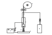
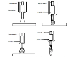
Metal transfer in inert gas welding.
DIFFERENT APPLICATION IN INDUSTRY
| Shielded metal arc welding. |
SMAW can be used for a variety of metal types and various thicknesses. It is often used for heavy-duty work involving industrial iron and steel, like carbon steel and cast iron, as well as work involving low- and high-alloy steels and nickel alloys. SMAW is used in a variety of industries, including:
|
| Submerged arc welding. | Submerged arc welding is commonly used in industries where thick steel sheets are involved or where long welds are required. The process consists in creating a welded joint between steel components using an electric arc submerged beneath a layer of powdered flux. |
| Gas tungsten arc welding. |
TIG is applied in all industrial sectors but is especially suitable for high quality welding. TIG is also widely applied in mechanised systems either autogenously or with filler wire. However, several "off the shelf" systems are available for orbital welding of pipes, used in the manufacture of chemical plant or boilers. The systems require no manipulative skill, but the operator must be well trained. Because the welder has less control over arc and weldpool behaviour, careful attention must be paid to edge preparation (machined rather than hand-prepared), joint fit-up and control of welding parameters. |
| Plasma arc welding. |
The applications of PAW mainly include the following.
|
| Metal inert gas welding. | MIG/MAG is widely used in most industry sectors and accounts for more than 50% of all weld metal deposited. Compared to MMA, MIG/MAG has the advantage in terms of flexibility, deposition rates and suitability for mechanisation. However, it should be noted that while MIG/MAG is ideal for 'squirting' metal, a high degree of manipulative skill is demanded of the MIG welder. |
5-) 3-2-1 Principle
Locating a part to be machined involves mainly three steps: Supporting, Positioning, and Clamping.
Two main intentions when placing a job on a jig/fixture are:
- Precisely positioning the part at the desired coordinates.
- Curbing all six degrees of movement so that the part cannot budge.
An extensively used method for obtaining these objectives is the 3-2-1 principle or six degrees of freedom for part location.
The 3-2-1 method is a work-holding principle where three pins are located on the 1st principle plane, i.e., either XY, YZ, ZX. And two pins are located on the 2nd plane perpendicular to the 1st plane, and at last, one pin on the plane is mutually perpendicular to the 1st and 2nd planes. The aim is to constrain the movement of the workpiece along all three axes.
Design objectives of Jigs and Fixtures
Before sitting down to design jigs/fixtures, the designer must consider the following points:
- The tool must be foolproof to prevent any mishandling or accidental usage by the operator.
- Easy to operate for increasing efficiency.
- Easy to manufacture using the lowest costs.
- Its ability to weather the tool life instead of appropriate materials.
- Must be consistent at producing high-quality parts.
- Must be safe and secure to use.
The designer must know the basics of the process and the tools associated with it for which the jig/fixture is designed. Overall objectives to look out for a while developing such tools are:
- Cycle time.
- Type of Jig/Fixture.
- Part Assembly sequence or Machining locations.
- Joining or machining process.
- Clamping method and clamping sequence.
- Required output accuracy.
- Type of equipment to be used with the jig.
- Method of ejecting finished output and transferring it to the next. Platform, whether the manual or automatic mode.
- The type of material, recommended weight, number of spots involving welding.
6- BODY COORDINATE SYSTEM ( PART LOCATING SYSTEM)
Car lines are the (Grid lines) shown on the fixture , which virtually represent the same location in the BIW. All the car line on fixture display the coordinate at corner for reference . With these lines one can easily relate the ,location in BIW.
Some times single coordinate hole is given in the fixture ,that also represent the car line coordinates, from that reference point fixture is made and can be inspected . Body coordinate are mentioned near the hole
Below picture shows the grid line on fixture
Maintaining X,Y & Z co-ordinates in fixture is a very important factor.
We should try that the co-ordinates of locating and clamping points should not be in three decimal (e.g. X=100.124, Y=245.127, Z=450.458).
They should be in the whole nos. or max upto 1 decimal . Once these co-ordinates are maintained automatically the BIW base structure is maintained.
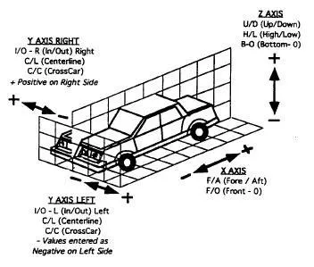
All vehicle product drawings are identified numerically relative to three vehicle planes Description shown below.
1. ( X ) It is in length of BIW – 0 X is Near Front Bumper
2, ( Y ) It is in width of BIW – 0 Y - is Body Center Line
3. ( Z ) It is in Height of BIW - 0 Z is about Center of Wheel
Body Coordinate system on which BIW Geometry is maintained and Designed
Figure below illustrates a typical body coordinate system.
7-BODY PLANE SYSTEM AND IT'S ESSENTIALS
It is basically a three imaginary planes with respect to these planes all other body parts is located / positioned
- It is used to locate the part with respect to the origin.
- Using this system ensures that assembly of part is proper.
- This system helps in quality check.
- This helps in creating the standardize the system.