Fender Design Challenge
AIM- To design the Drip area mounting, A pillar mounting, Sill mounting, Bumper mounting and Baffle region mountings on the main body of the fender using NX CAD software.
What is fender?
Fender is the component that frames the wheel well, its' primary purpose is to prevent the sands, mud, rocks, liquids and other road spray from being thrown into the air by the rotating tire.

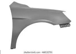
When the vehicle is moving the tyre pick up the mud particles, pebbles and throw them in a tangential direction after that the spatter of these particles occur in all the direction due to the collisions happens to the near by surface therefore
decreasing the pedestrian safety as well as the decreasing the life of the components which are situated near to the wheels.
CLASSIFICATIONS OF THE FENDER
Fender are classified into two types as follows
FULL BUMPER TYPE
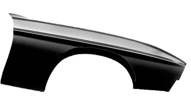
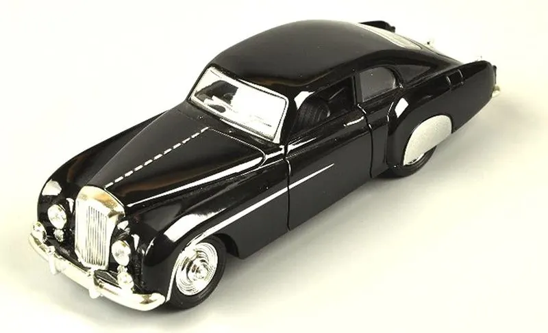
These types of fender cover the wheel well and it is stretches upto the head light, these type of fender are obsolete now a days as a lot of material got wasted while making these types of fender
also using these type of fender will result into increase the weight of the car.
HALF BUMPER TYPE
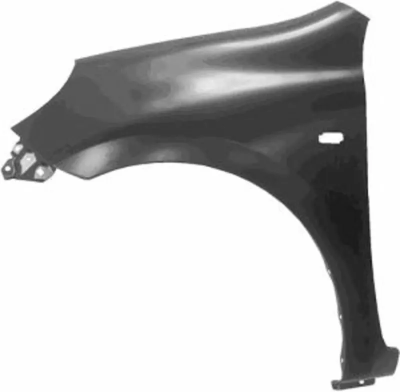

These types of fender covers half of the portion what full bumper type fender does, It is now used mostly used by all the cars as we can save a lot of material practically we can make two half bumper type from the single blank also the weight of the car is considerably reduced while using this fender.
Manufacturing process involved to make fender
1- Stamping- It is produced by the downward stroke of the ram when the punch moves towards and into the die block, the punch and die block assembly is generally termed as a die set ,the operations are usually done at room temperature.
we have to consider the positive draft for easy removal of the tool also ensuring the longer tool life. Values of draft angles for a particular material are as follows.
Sheet metal--- 7 deg.
Plastic -- 5 deg.
2- Bending - Bending is one very common sheet metal forming operations used not only to form shapes like seams, corrugations and flanges but also to provide stiffness to the part (by increasing the moment of inertia).
When we do bending operation to the workpiece the top most fiber experiences the tension and the bottommost fiber experiences compression and because of the poission ratio property the width of the workpiece above neutral layer decrease.and below the neutral
axis it is increases.
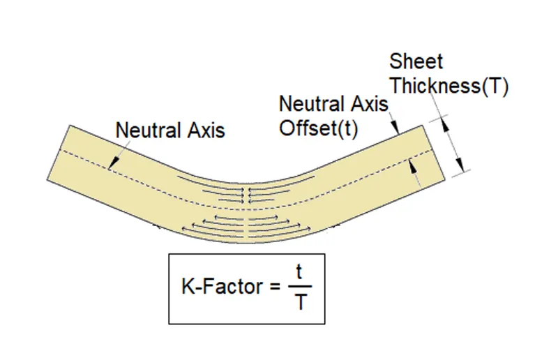
In order to make the flange of drip area we have to consider the effect of spring back effect
SPRING BACK In bending when the applied load is removed, the metal tries to regain its original positions this results in a smaller bend angle and a larger bend radius than before, such a phenomenon is termed as spring back
spring back for some common metals are
Low carbon steel --> 1 to 2 deg.
Medium carbon steel --> 3 to 4 deg.
In order to avoid the spring back we can provide the above values in addition with the bend angle or we can provide L shape structure to the wall.
DIFFERENT MOUNTINGS ON THE FENDER
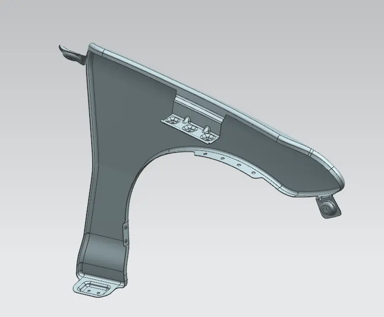
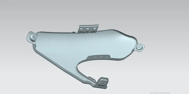
1- Drip area mounting - This mounting is situated near to the engine compartment we have to leave the Gap of 200 mm from the cowl side and 150 mm from the headlight We have to maintain the level mounting as constant and if it is not possible try to maintain either uniform increasing or decreasing.
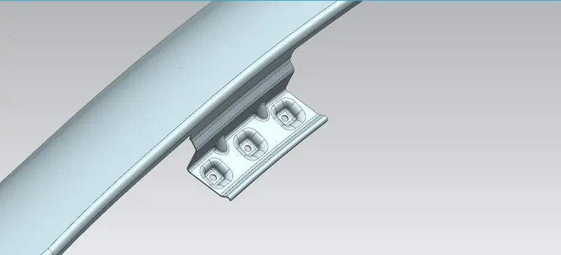
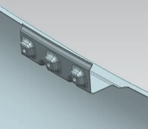
2- A-pillar mounting - This type of mounting we provide it on the fender in order to attach it to the A-pillar of the windshield flange.
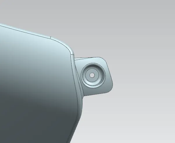
3- Bumper mounting - Here we provide mounting on the fender in order to attach it from the bumper.
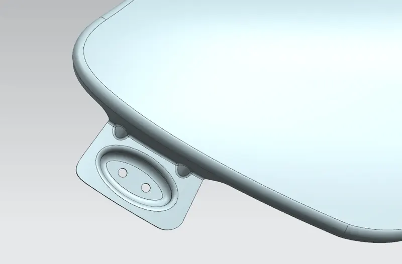
4- Sill mounting- We provide mounting on the fender in order to attach it to the sill area of the car.
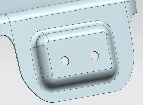
5- Baffel region mounting This type of mounting we provide it on the fender in order to attach it to the underside area of the wheel well.
We are attaching it through the push pin.
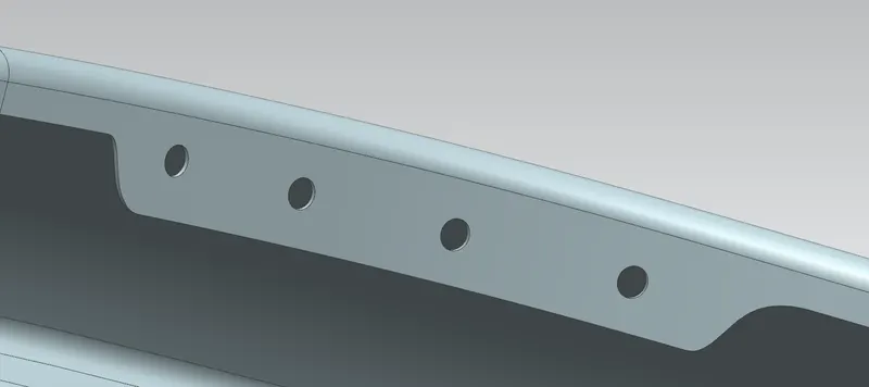
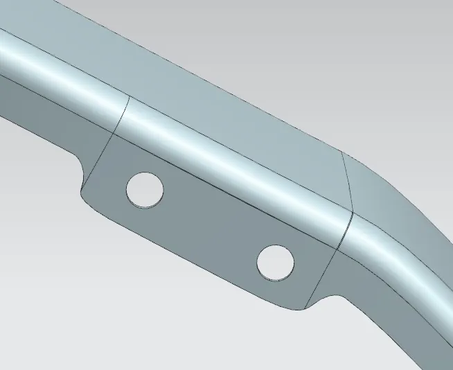
Overall view of fender
CONCLUSION
All the mountings are successfully designed on the fender skin while considering the ease of manufacturing of the mountings.