Design of backdoor
Aim- To design the backdoor while providing all the necessary mountings and reinforcements for Hinges, Gas stay, Wiper motor mountings and latch striker using Top Down assembly in NX CAD.
Backdoor introduction
It is a door panel which provides access to the boot space for luggage in the rear part of the car. Material we used generally used are steel and aluminium it depends on the segment of a car for luxury car we use aluminium.
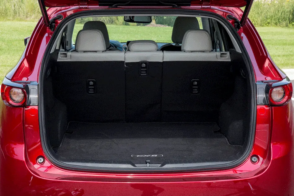
Types of backdoor based on the position of hinge axis
- Top mounted.
- Side mounted.
- Bottom mounted.
1- Top mounted : Here the hinge is mounted on the upper side of the car so that the door is open in the upward direction.
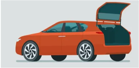
Examples- Hatchback, Sport utility vehicles (S.U.V)
2- Side mounted : Here the hinge is mounted on the sideways of the rear side of the vehicle, this arrangement is made for medium to extra heavy level of goods and carriage services.
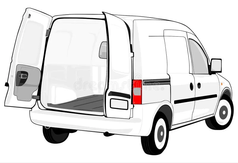
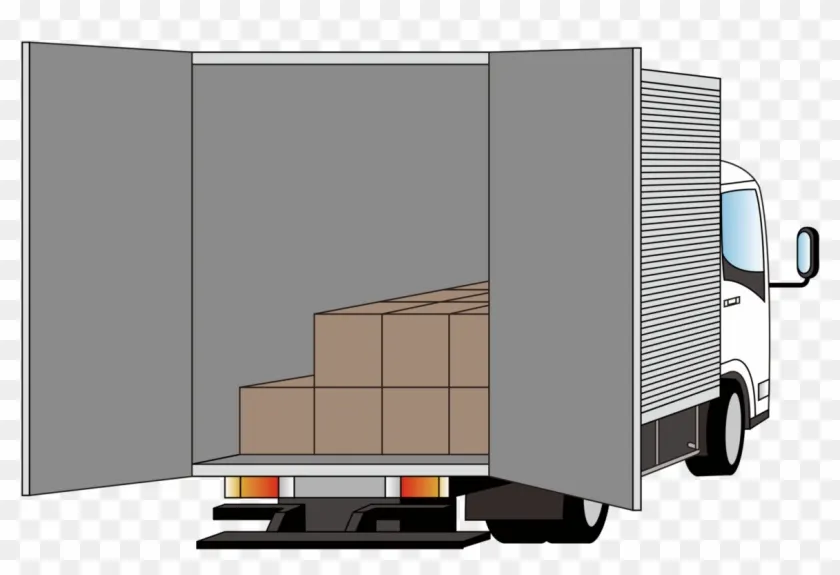
Examples - Van, Ambulance vehicle etc.
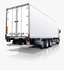
3- Bottom mounted : Here the hinges are mounted on the bottom of the rear side of the vehicle, this arrangement is made for heavy load capacity vehicle or vehicle with platform type chassis
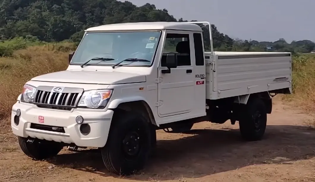
Examples : All platform type vehicle, Truck etc.
Here in this challenge we are going to design the backdoor of the hatch back.
Hatchback : Here the hinges are mounted on the top side of the vehicle i.e. on the roof side. Hatchback is design as 2-box [ hood , ( passenger compartment + boot space)]
here rear seat can be folded to increase the boot space of the car.
Design consideration of backdoor
1- Rear visibility criterion
2- Boot space
3- Should pass all kind of test ( Bend test, Dent test, Torsion test, Endurance test etc.)
4- Rear crash
5- Functional requirement of Hinge and gas stay.
6- Functional requirement of Latch and striker.
Features of backdoor
- Outer panel upper and lower.
- Inner panel.
- Hinge mounting and reinforcement (L.H and R.H).
- Gas stay mounting and reinforcement( L.H and R.H).
- Wiper motor mounting and reinforcement.
- Latch mounting and reinforcement.
Outer panel upper and lower
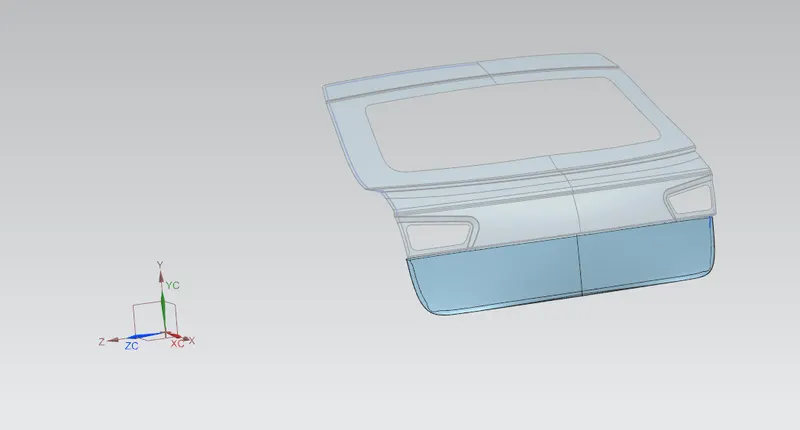
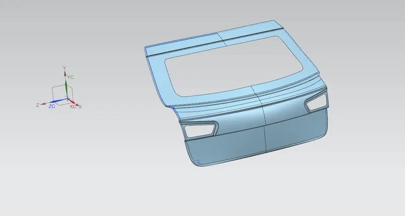
Here we receive the step file of the backdoor first we have to rectify the class A surface of the backdoor, this surface are responsible for the aesthetic and aerodynamic aspect of the car.
here we thicken both outer panel upper and lower in downward direction of thickness 0.75mm.
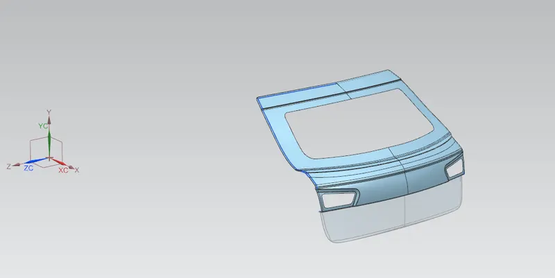
Outer panel upper Outer panel lower Outer panel
Inner panel
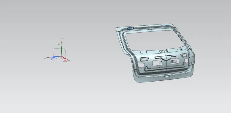
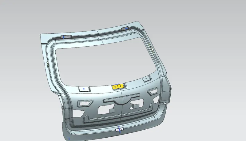
- It is the skeleton of the outer surface, that is, it provide sufficient strength to the outer surface and all the mounting is done with the inner panel.
- we use steel and aluminium for producing inner panel,
- we create embosses to locally increase the strength of inner panel by increasing the section modulus also if crash happens first load is taken by the embosses and force is going to dissipate according to the shape of emboss after that it will hit to the inner panel.
Hinge mounting and reinforcement
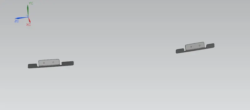
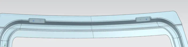
In order to open or close the backdoor we use hinge and to accomodate the hinge pin correctly we have to provide the plane surface in order to maintain surface contact rather than point or line contact and reinforcement is provided in order to increase the strength of mounting flange here we provide the thickness of 1.5 mm
Gas stay mounting and reinforcement
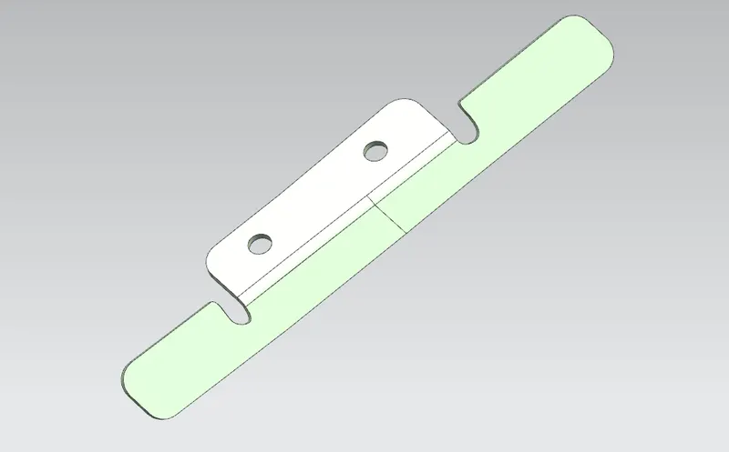
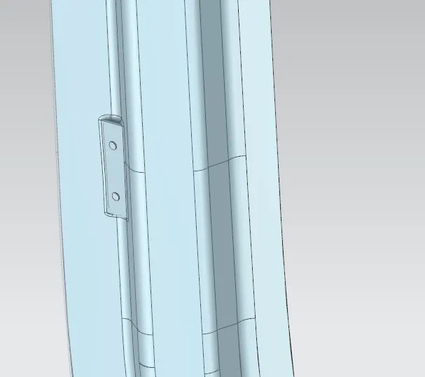
Gas stay is used to hold the backdoor of the vehicle in open conditions with the help of support rod, so we have to make the gas stay mounting on the inner panel since we are consider steel material for the manufacturing of backdoor and we adopt the stamping process for the manufacturing of the gas stay mounting, in order to provide the strength to the mounting we have to provide the reinforcement of thickness value of 1.5mm.
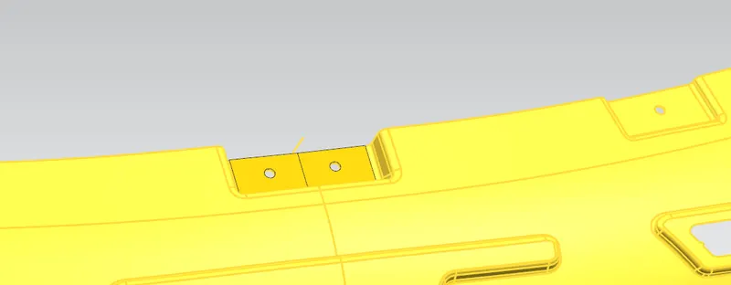
Wiper motor mounting reinforcement
In order to accomodate the wiper motor we have to provide mounting on the inner panel for wiper motor and in order to ensure the strength of mounting we provide reinforcement of thickness 1.5mm
.
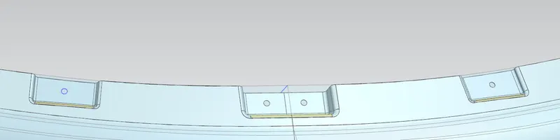
Latch and striker reinforcement
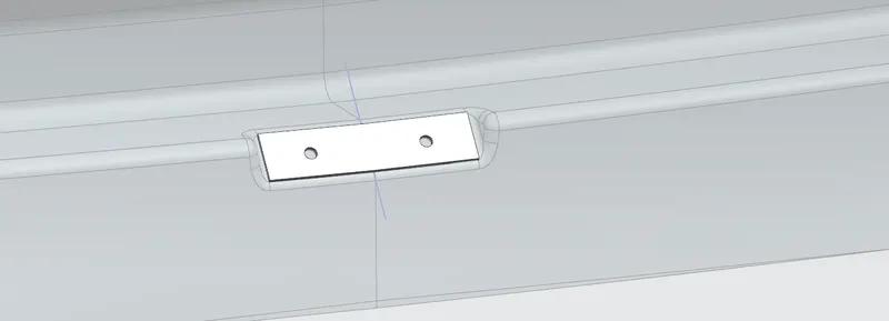
We also provide mounting for the latch and to ensure the strength of the mounting we provide reinforcement of thickness 1.5mm.
.
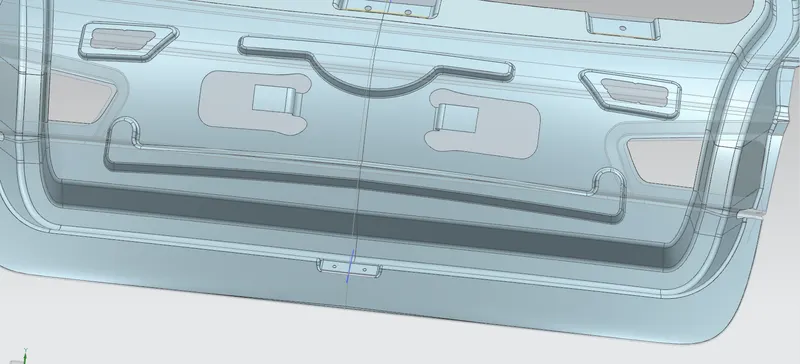
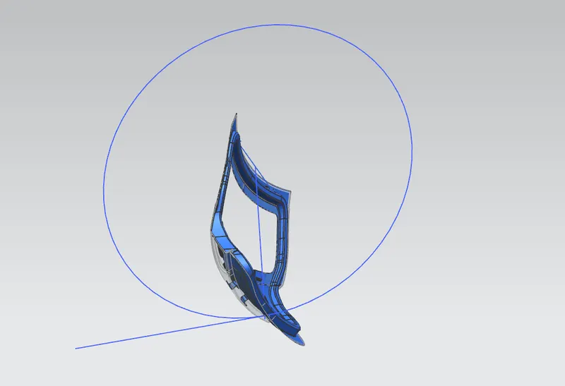
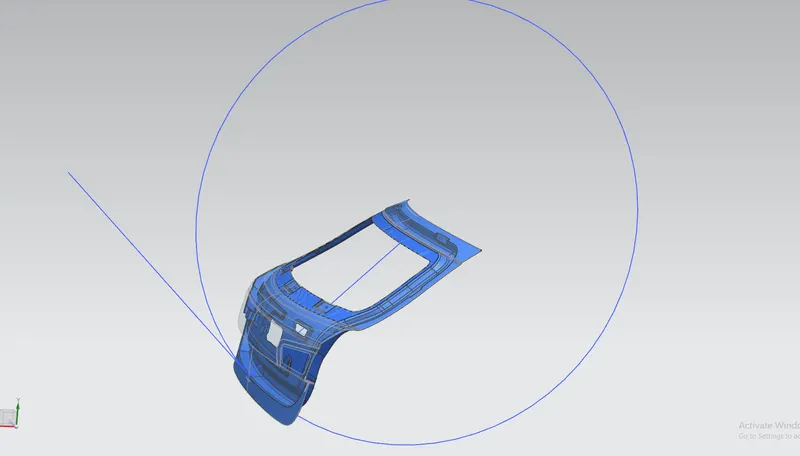
Locus/ Trajectory of the striker
In order to ensure that the striker can completely fit into the latch we have to make sure that at every point on the trajectory line of action of the striker should be perpendicular to the radius of the trajectory.
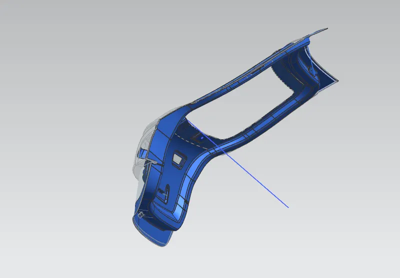
OVERALL ASSEMBLY OF INNER PANEL
.
Mastic glue
It is a paste like substance, it is get cured to the higher temperature and become the elastic hard material, it is used for the joining of the inner panel to the outer panel without deteriorating the aesthetic look of the outer panel we apply the mastic glue between the inner and outer panel and at corner we do the hemming operations we have to provide the space of 4 to 5 mm for effective use of the mastic glue.
surface needs to be clean while applying the mastic glue.

MANUFACTURING PROCESS
Embosses
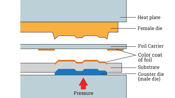
Sheet metal embossing is a stamping process for producing raised or sunken designs or relief in sheet metal. This process can be made by means of matched male and female roller dies, or by passing sheet or a strip of metal between rolls of the desired pattern.but it should be done with respect to the tooling direction but it should be done with respect to the tooling direction.
Metal sheet is drawn through the male and female roller dies, producing a pattern or design on the metal sheet. Depending on the roller dies used, different patterns can be produced on the metal sheet. The pressure and a combination of heat actually “irons” while raising the level of the image higher than the substrate to make it smooth. The term “impressing” refers to an image lowered into the surface of a material, in distinction to an image raised out of the surface of a material.
Tooling direction
Before creating embosses we need to create the line which represent the tooling direction basically the tooling direction is the axis of the advancement of tool (ram) towards the workpiece.
method for creating tooling direction
create two points on the extreme end of the workpiece then draw a line using it after that create a line perpendicular to that line this new line will bw our tooling direction.
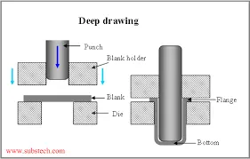
Deep drawing
Deep drawing or a cup drawing is a process of forming hollow shaped components from the flat pieces of sheet metal or from lready drawn components, a large variety of components such as kitchen utensils ,boxes of various shapes, components of car bodies, domestic gas cylinders etc. are made by deep drawing.
the equipment consists of the die with a central hole having a profile radius, a blank holding plate which keeps the sheet pressed on the flat die surface and a punch with a suitable diameter and corner radius.
the motion of punch pushes the bottom of cup into the die the sheet around the punch pulls the remaining sheet into the die to form a cup the flat sheet between die and blank holding plate move towards the die center against the frictional forces between sheet and die surface and between sheet and blank holding plate the sheet then bends over the die profile radius slips over it against the frictional forces and then unbends it into the cup wall
each of these processes increases the tensile stresses in the cup wall the maximum tensile stress occur at the punch profile radius where the sheet bend over it under tension generally the failure takes place near the punch profile radius since the tensile stress is the cumulative stress due to drawing of flange bending and unbending of sheet at die profile radius frictional effect on die profile radius and lastly due to bending on punch profile radius
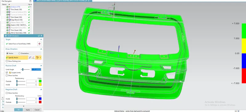
Draft analysis
We have to check whether it is feasible to manufacture the components for this we have to do draft analysis
Draft analysis for the inner panel
CONCLUSION
We have successfully designed the backdoor with all the mounting and reinforcement while considering all the manufacturing criterion needed using NX- CAD.