To Generate seismic loading based on IS code and to run the analysis using TSD
- Generate seismic loading based IS codal provisions and zone II. Any other data you can assume and input accordingly
AIM:- To generate seismic loading based IS codal provisions and zone II. Any other data you can assume and input accordingly
INTRODUCTION:- Seismic load are the earthquake load on the structure which acts from ground and transfer to the top the building. The Structure must be designed in such a manner to resist the seismic force. IS 1893 part 1 are followed for seismic loadcase.
PROCEDURE:-
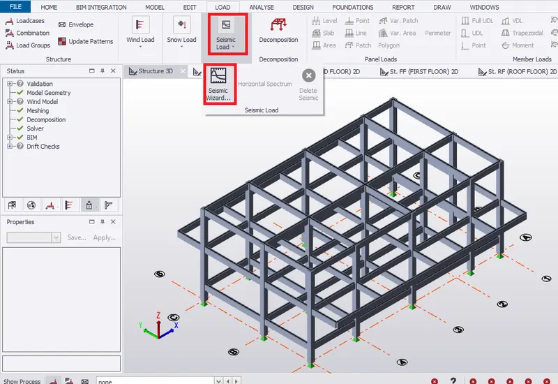
- Select Seismic Load (Seismic wizard) ribbon from Load tab.
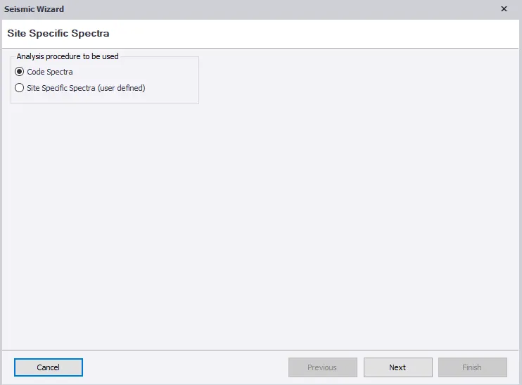
- Select Code spectra for analysis procedure. Click Next.
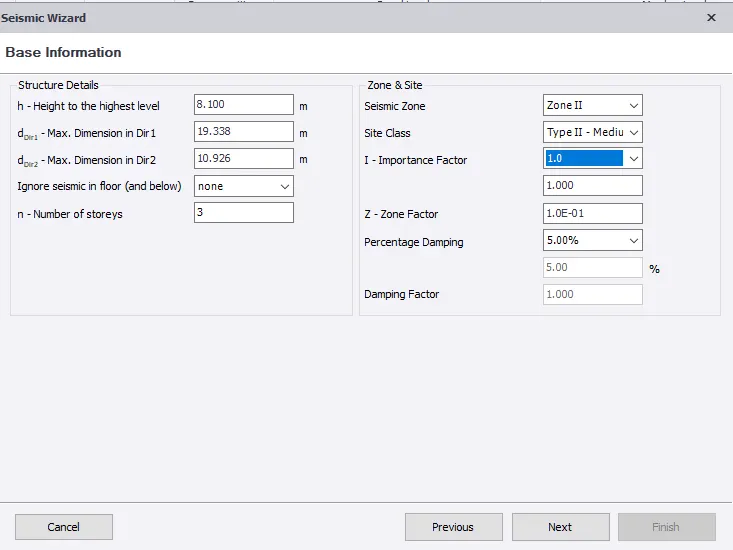
- Structural Details under base information is automatically inputed.
- Set the seismic zone to 2 and site class to 2 as shown below.
- Importance factor and percentage damping is obtained from Table 6 and 3 respectively of IS 1893-1 and zone factor from Table 2
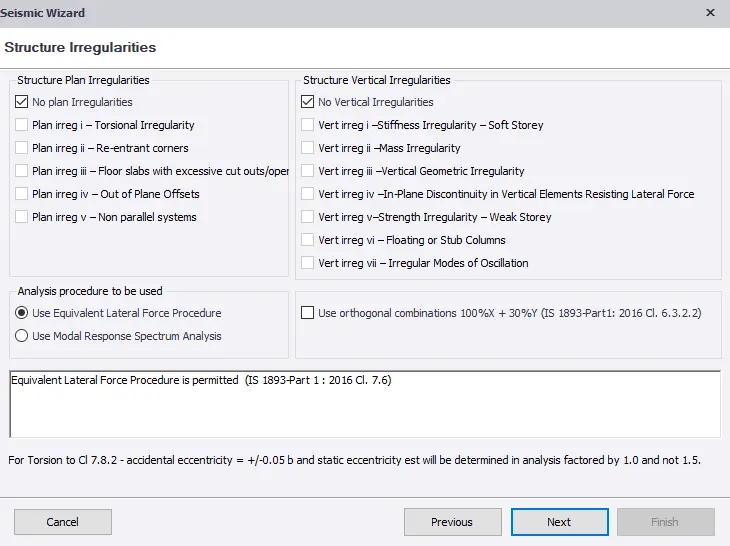
- No structural irregularity in the structure as mentioned in Table 4 and 5.
- Use approxmiate fundamental period. Set RC MRF building without any masonry infill in both direction.
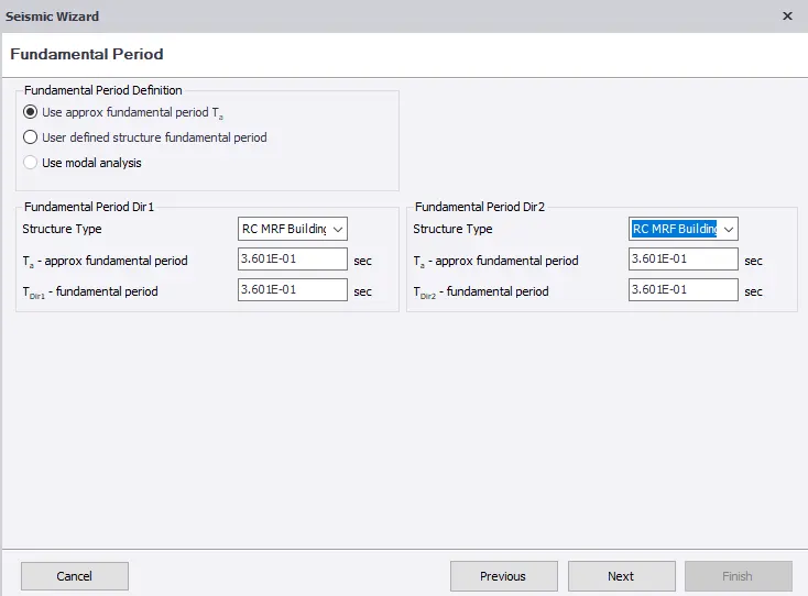
- Set structure type to seismic force resisting system in both direction.
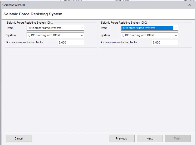
- Select all the loadcases and set factor for imposed load to 25% for refered from table 8
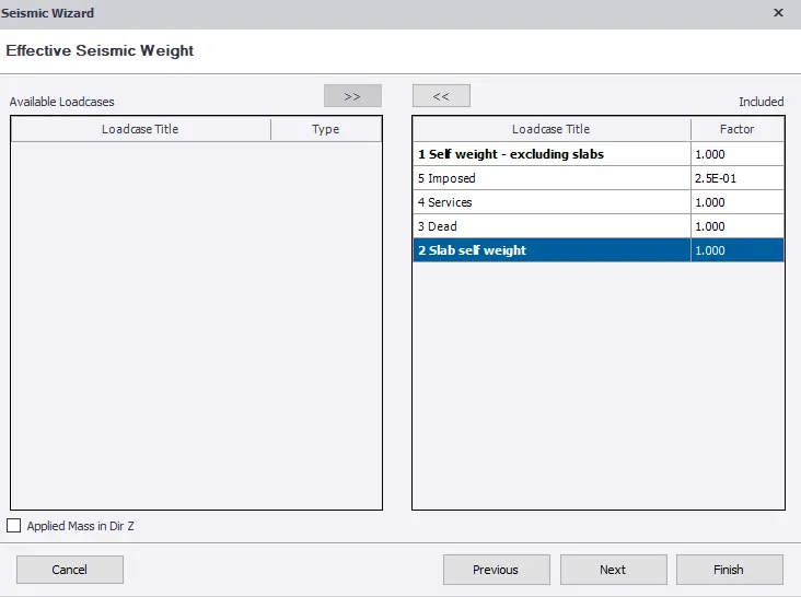
- Set allowable storey drift factor as 0.004. Click finish.
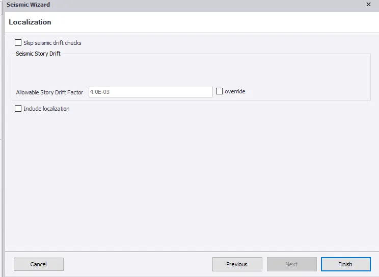
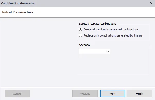
- Delete all previously generated combinations.
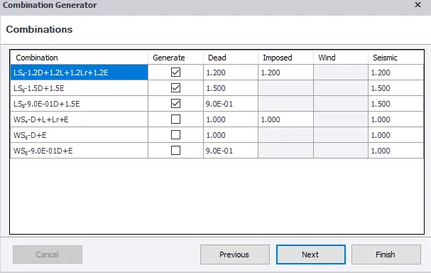
- Select the combinations to be generated.
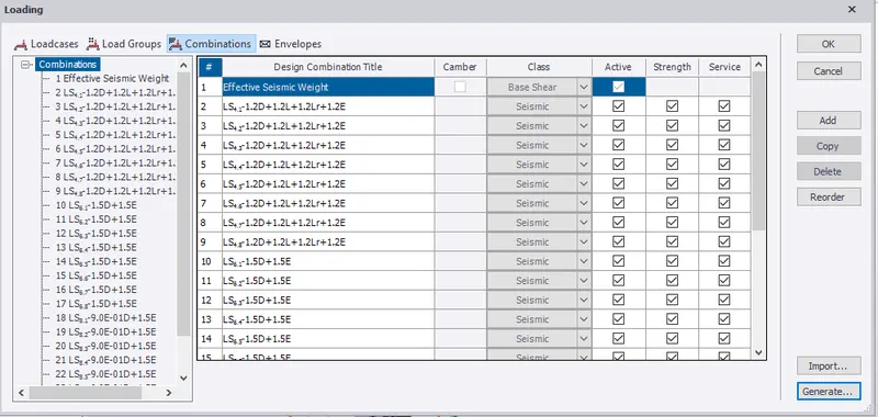
- Select the load combination from load tab to check the combination generated.
- Click on generate to replace only combinations generated by this run.
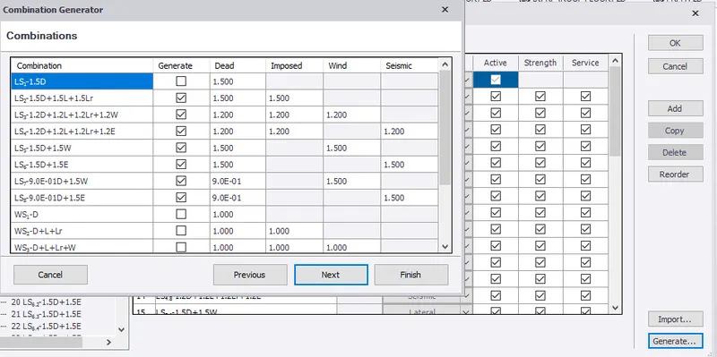
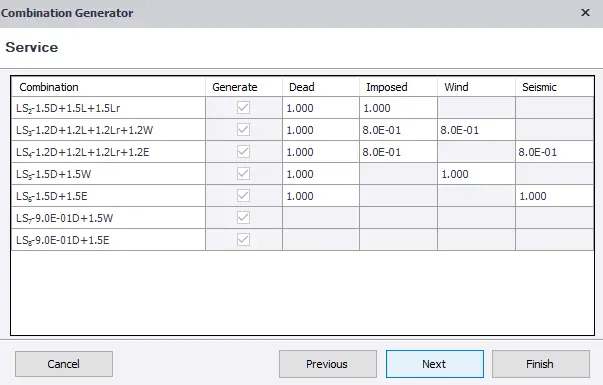
- Click finish.
- Therefore, load combinations are generated.
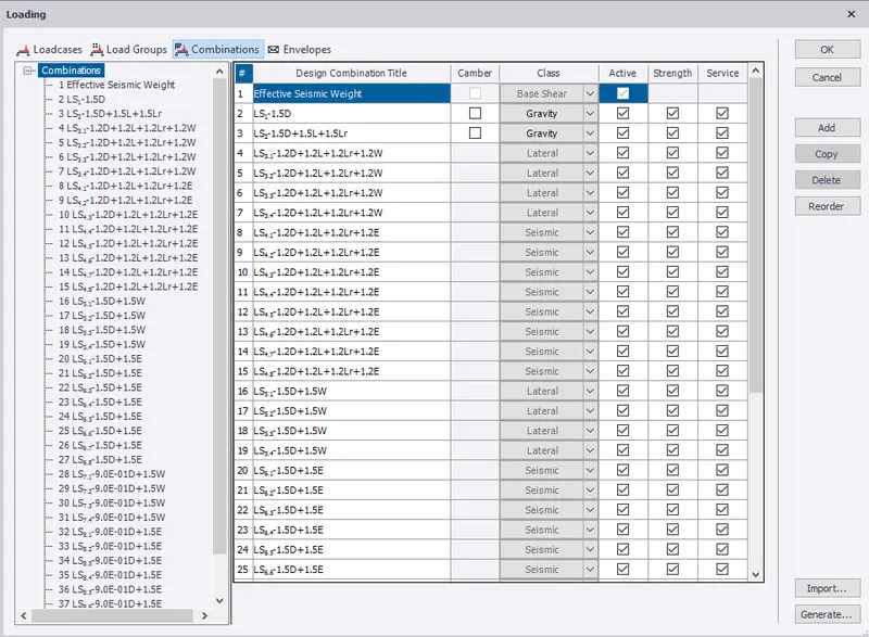
RESULT:- Hence, seismic loading are generated based IS codal provisions and zone II.
2. Run the analysis. Summarize your understanding of the analysis results
AIM:- To run the analysis and to summarize the analysis results
INTRODUCTION:- Analyical diagrams like Bending moment, Shear force, Axial force and deflection are used for the study of behaviour of each member of the building.
PROCEDURE:-
- Go to analyse, under settings check modification factor for concrete as 1.
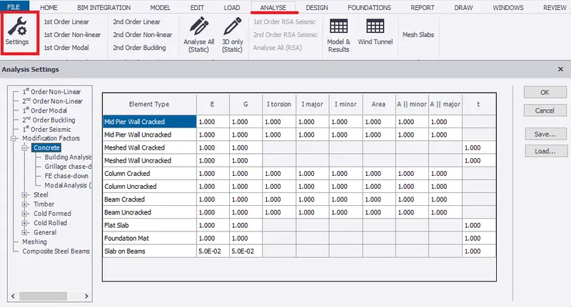
- Run under 1st order analysis. Select all load combinatons.
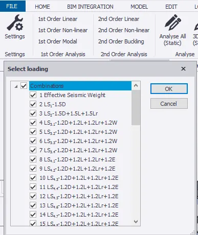
- After run analysis, the status shows no error.
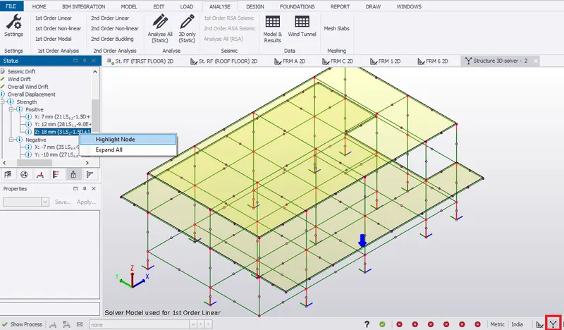
- Expand the overall displacement, check the maximum positive displacement for both strength and service in solver view.
- Highlight the node for displacement along z axis to check maximum displacement for the member as shown
- In results view, under results select deflections for different load combinations. Therefore, maximum deflection is shown in load combination 3
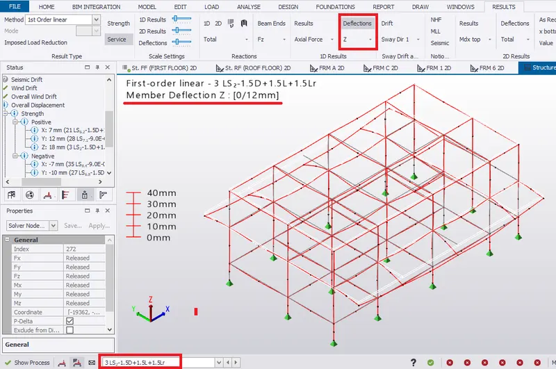 DEFLECTION DUE TO GRAVITY ON THE STRUCTURE
- Select the frame 3 from project window, to check the deflection diagram.
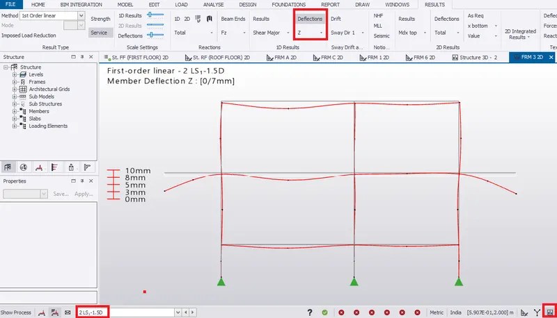 DEFLECTION DUE TO GRAVITY
- The deflection due to gravity in picture above is correct.
- But the deflection at the cantilever ends are high.
- Similarly, check for different load combinations
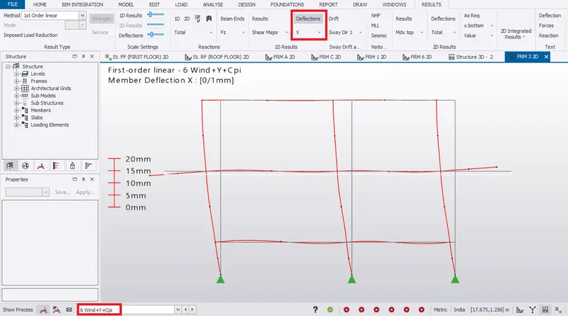
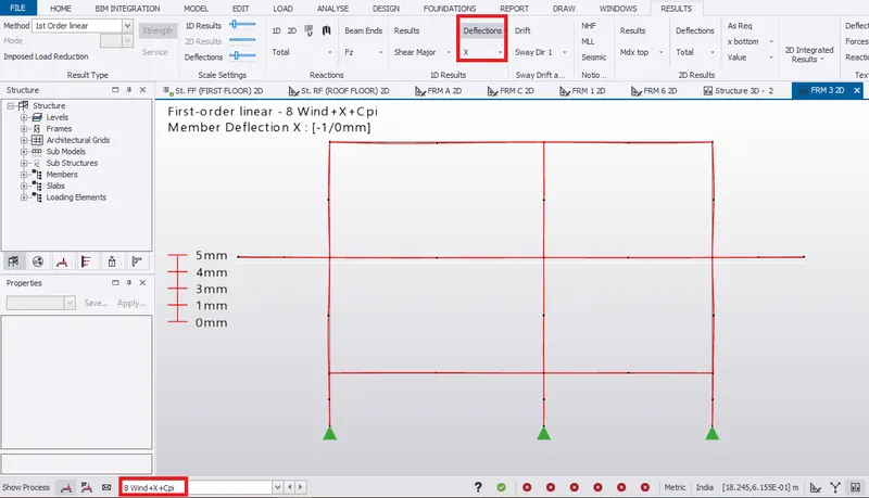
- Deflection due to wind is shown below.
Axial force
- In result view, select Axial force from results tab.
- Maximum axial force for column is shown for load combinations 3.
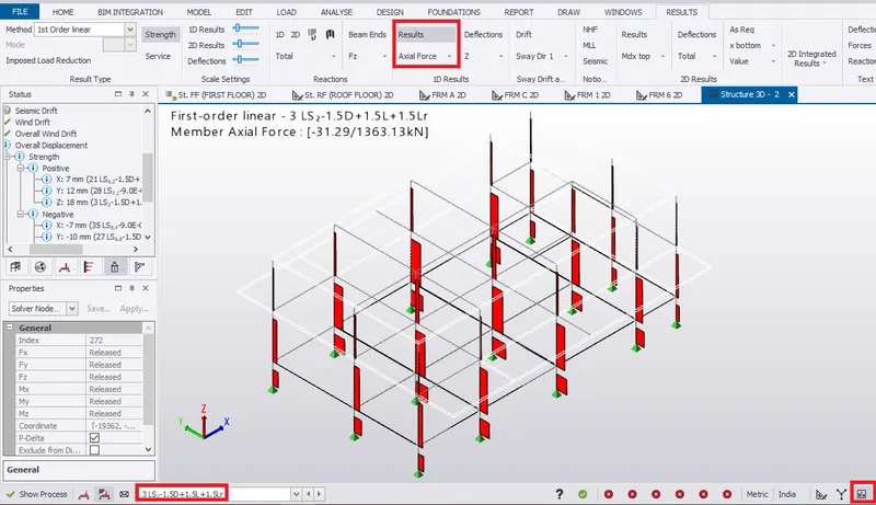
- Select the frame 3 from project window, to check the axial force diagram.
- The axial force is acting maximum at bottom of the column which is correct.
- Similarly, check for different load combinations
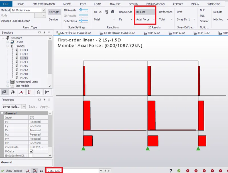 AXIAL FORCE FOR GRAVITY LOAD
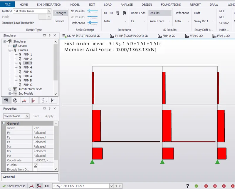 MAXIMUM AXIAL FORCE FOR LOAD COMBINATION 3
Bending Moment
- For frame 3, select moment major from results tab.
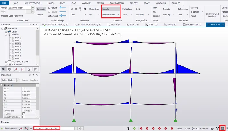 MAXIMUM BENDING MOMENT IS SHOWN IN LOAD COMBINATION 3
- Bending moment at the end of the cantilever beam is 0 which is correct.
- Similarly, check for diffenent load conditions such as wind and seismic.
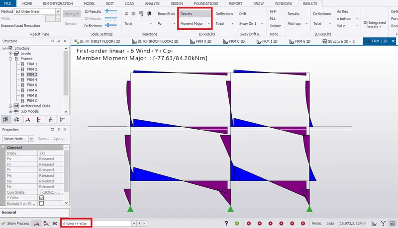 BENDING MOMENT FOR WIND LOAD CONDITION
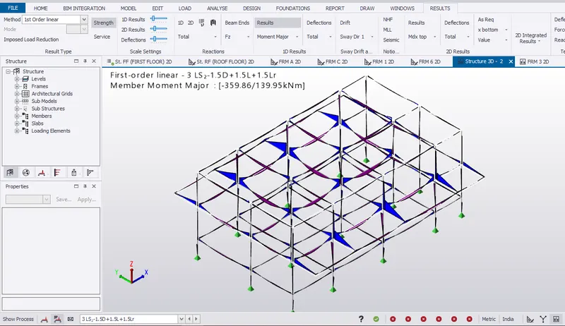 MAXIMUM BENDING MOMENT ON THE STRUCTURE FOR LOAD COMBINATION 3
Shear force
- For frame 3, select shear major from results tab.
- Check shear major for different load conditions and combinations.
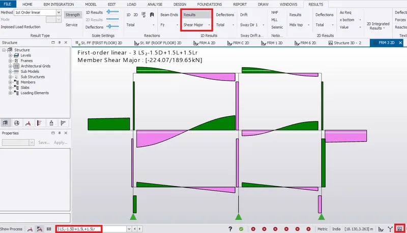 MAXIMUM SHEAR FORCE IN LOAD COMBINATION 3
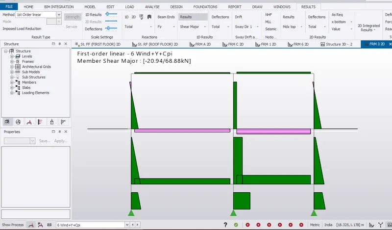 SHEAR FORCE FOR WIND LOAD CONDITION
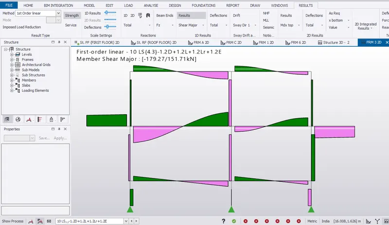 SHEAR FORCE FOR SEISMIC LOAD COMBINATION
RESULT:- Hence, summarized the analysis results obtained after run analysis.