To Model a RC residential structure using TSD
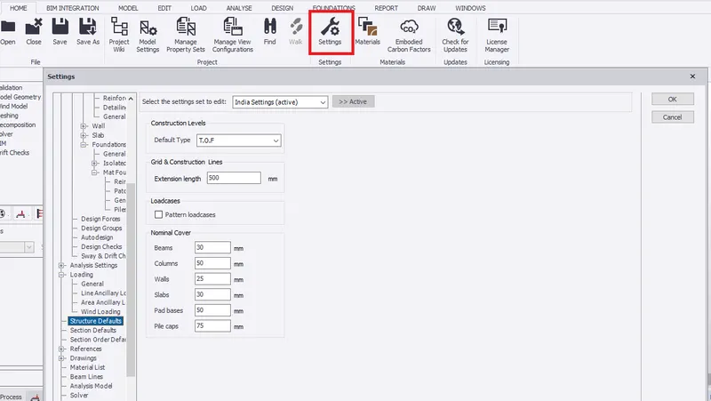
Setup model for RC building design and based on following parameters for cover
|
MEMBERS |
IN CONTACT WITH GROUND |
ABOVE GROUND |
|
Column |
50mm |
40mm |
|
Beam |
30mm |
25mm |
|
Slab |
30mm |
25mm |
|
Pilecap |
75mm |
|
|
Foundation |
50mm |
AIM:- To setup model for RC building design and based on the cover parameters
INTRODUCTION:- Setting must be done to specify the design code, design settings which includes reinforcement details and other criteria for each structural members and therefore set analysis.
PROCEDURE:-
- Open the TEKLA STRUCTURAL DESIGNER for design of RCC structure.
- Click NEW to open new file and save it to new name.
- Go to SETTINGS under HOME tab. Select structural defaults to set the nomial cover for each member in contact with ground
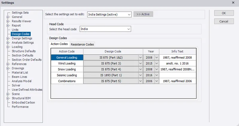
- Set the design code to Indian standard.
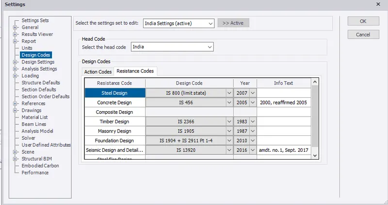
- In Design Settings, select beam under concrete to set reinforcement.
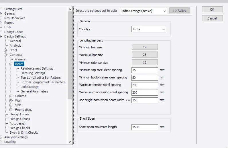
- Set reinforcement Detailing
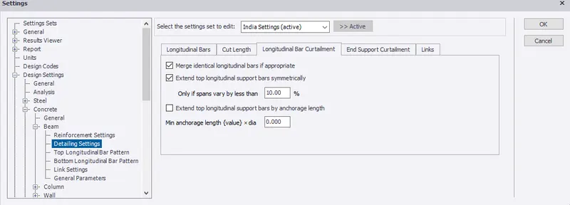
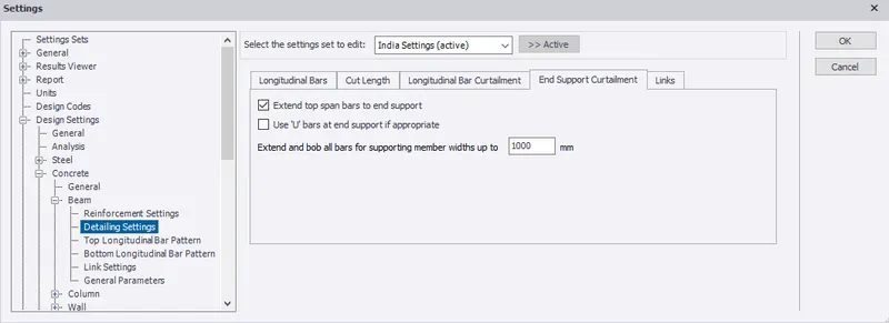
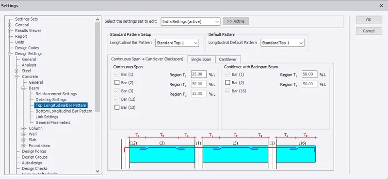
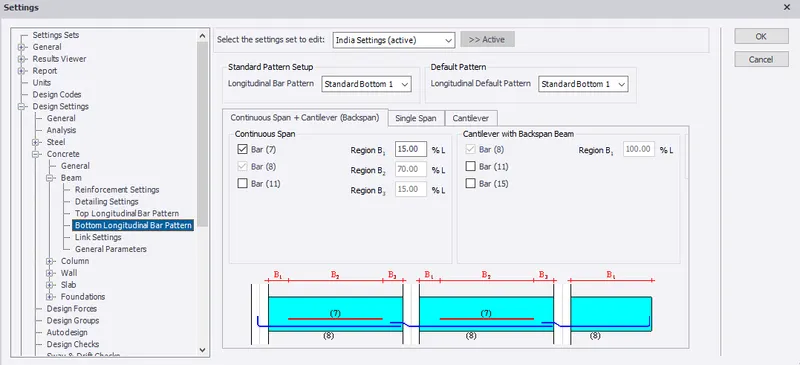
- Set top and bottom longitudinal bar pattern.
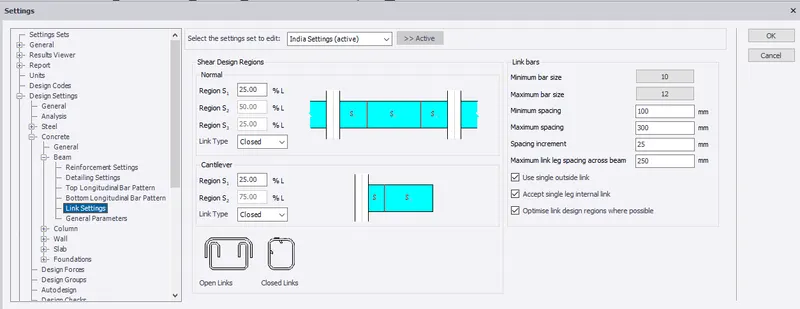
- Set links, ie, stirups details
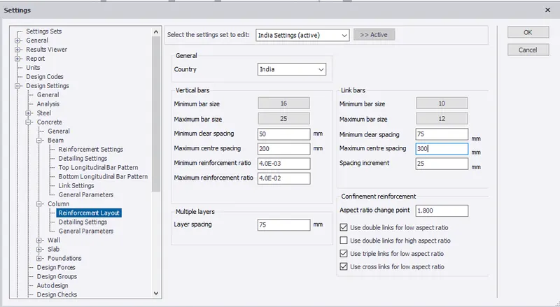
- Select column under concrete to set reinforcement details.
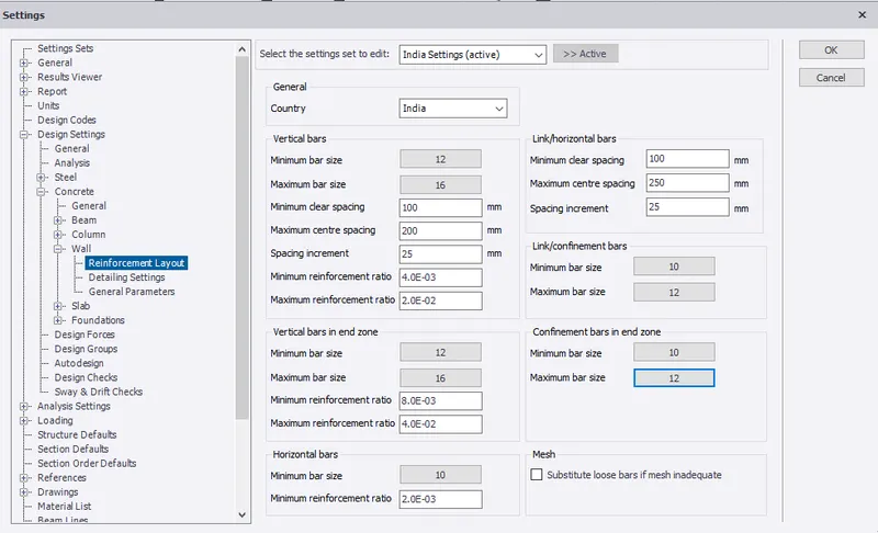
- Set reinforcement details for wall
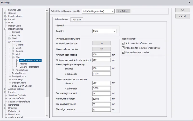
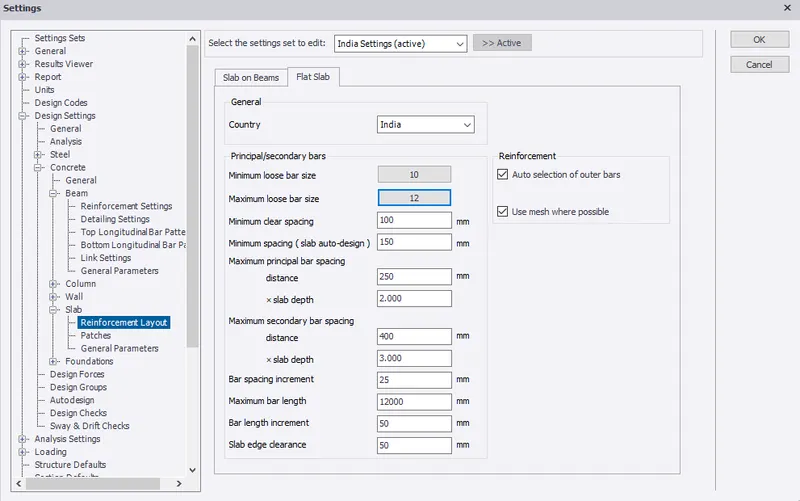
- Set reinforcement details for slab on beam
- Set reinforcement details for flat slab.
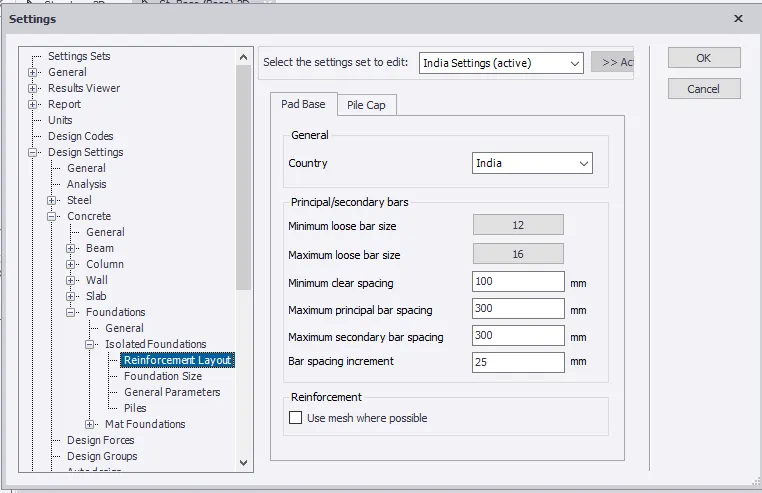
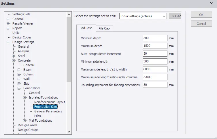
- Set reinforcement and size details for isolated foundation.
RESULT:- Therefore, model setup for RCC building design is completed.
2. Model grids as per the attachment 2,2.1 and 2.2
AIM:- To model grids as per the attachment 2, 2.1, 2.2
INTRODUCTION:- Grid line helps in easy arrangement of beams and columns for the structural member based on the attachment given.
PROCEDURE:-
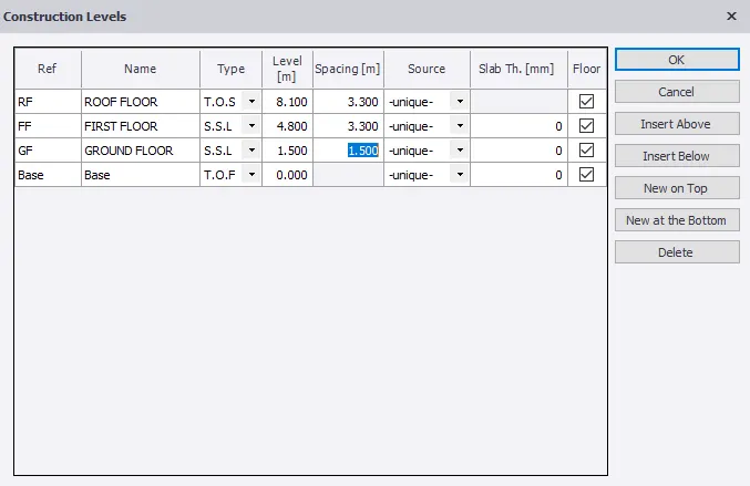
- Under MODEL, select Construction Level
- Select grid line under model to model grid line
- Pick the first and second point on the scene view to add the grid line.
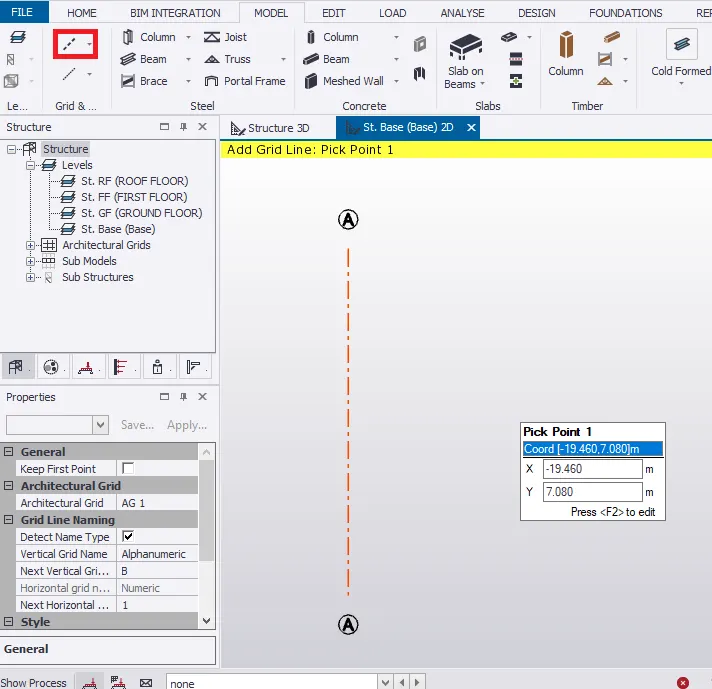
- Refer the plan drawing of the building to model the rest the grid line.
- Given, the brickwall thickness 225mm.
- Therefore, grid line distance for the office room should be (0.225/2)+ 4.5 = 4.6125m
- Similarly, construct parallel grid line for rest of the rooms.
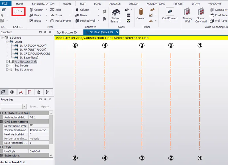
- Construct perpendicular line by picking grid line 6 as referance line.
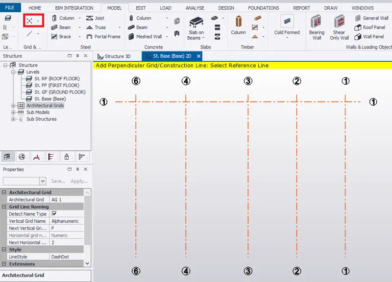
- Model grid line parallel to the perpendicular grid line.
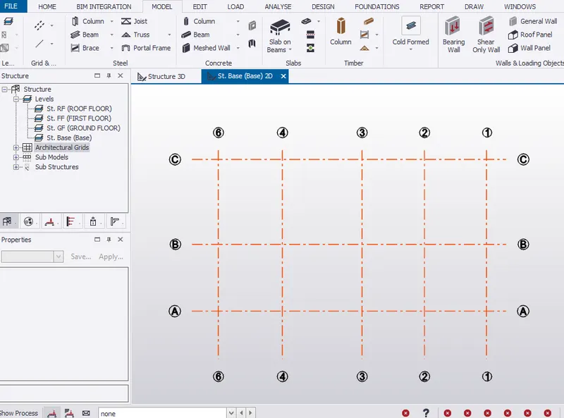
RESULT:- Hence, modelled grid line as per the attachment.
3. Study the layout and write a summary for general arrangement of the structure
AIM:- To study the layout and write a summary for general arrangement of the structure
INTRODUCTION:- Column are provided to carry the beam load in which beam load includes self weight and slab load distribution. Column should safely transfer the load to foundation.
PROCEDURE:-
Ground Floor
- Plinth beam must be provided beneath the ground level.
- Plinth beam must be provided at 1.5m from base.
- Column must be provided from base to roof level as per the attachment 2.1 with column position.
- The structure is an industrial building with rectangle size of 11.15m x 19.675m .
- Given, The brickwall thickness is 225mm.
- Ground floor provides provision for equipment rooms, office,etc directly to the ground.
First Floor
- Provide 3m height for the ground floor to first floor.
- In first floor, cantilever beams are provided for corridor portion with 2.62m width at both ends.
- The cantilever beam ends are supports by the simply supported beam.
- Slabs are provided in both 1 way and 2 way direction based on its ly/lx ratio.
- Slab loads are equally distributed to beams which are then transferred to column and then to foundation.
Roof Floor
- Provide 3m height for the first floor to roof floor.
- Slabs are provided in both 1 way and 2 way direction based on its ly/lx ratio.
RESULT:- Hence, layout of the structure is studied and summary of the general arrangement is noted.
4. Model RC columns, beams and slabs as per your general arrangement
AIM:- To model RCC columns, beams and slabs as per your general arrangement
INTRODUCTION:- Tekla structural Design is used for modelling of RC structures like beam, column and slabs by specifying its property sets and reinforcement details.
PROCEDURE:-
Column
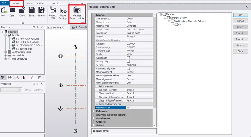
- Go to MANAGE PROPERTY SETS under HOME.
- Set property of RC column C1 with concrete grade M30 and size 400mm x400mm as shown below.
- Provide a nominal cover of 40 mm for RC column
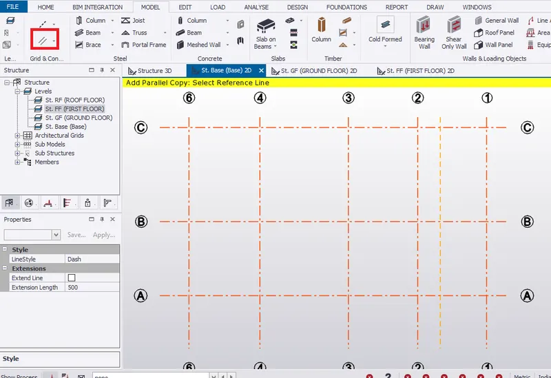
- Create 3m parallel construction line from grid line 1 to provide column for staircase.
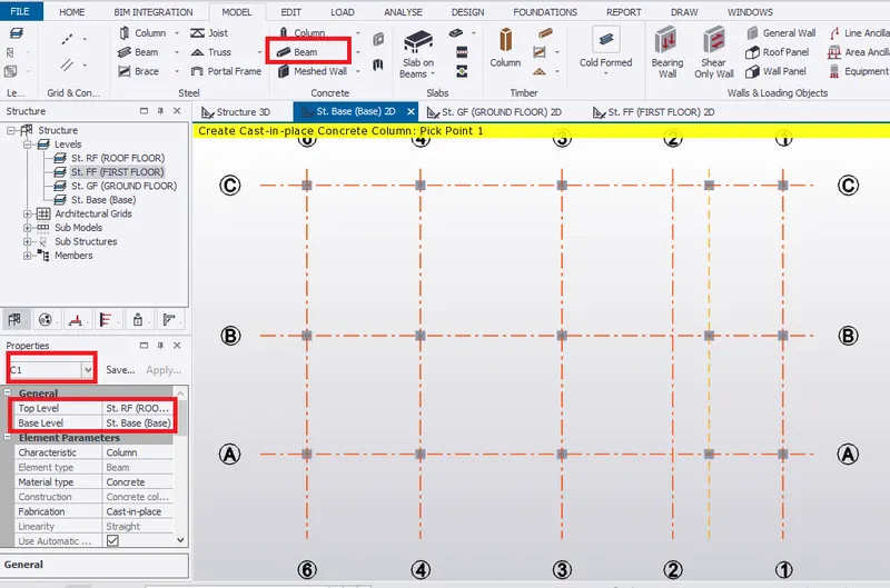
- Select concrete column from Model tab.
- Under property window, select C1 from base level to roof level.
- Pick the point of intersection to create the concrete column.
Beam
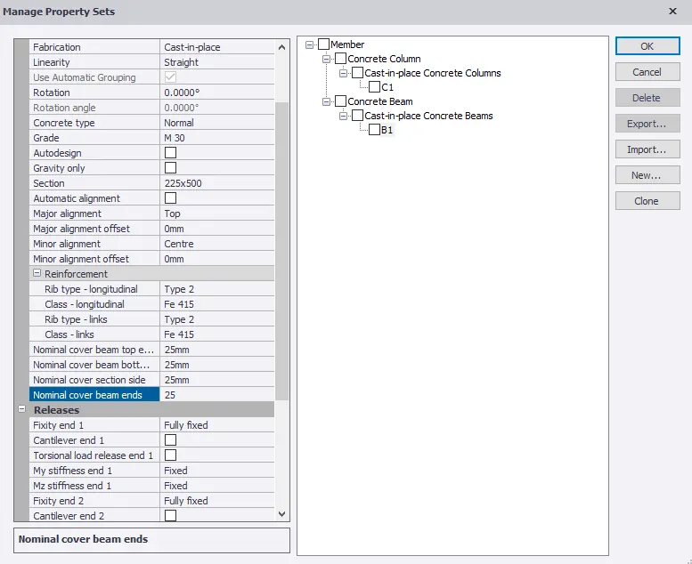
- Go to MANAGE PROPERTY SETS under HOME.
- Set property of RC beam B1 with concrete grade M30 and size 225mm x500mm since the brickwall thickness is 225mm.
- Provide a nominal cover of 25 mm for RC beam
- In ground floor, select concrete beam from Model tab.
- Under property window, select B1 continuous.
- Pick the point 1 to 5 to create the concrete beam.
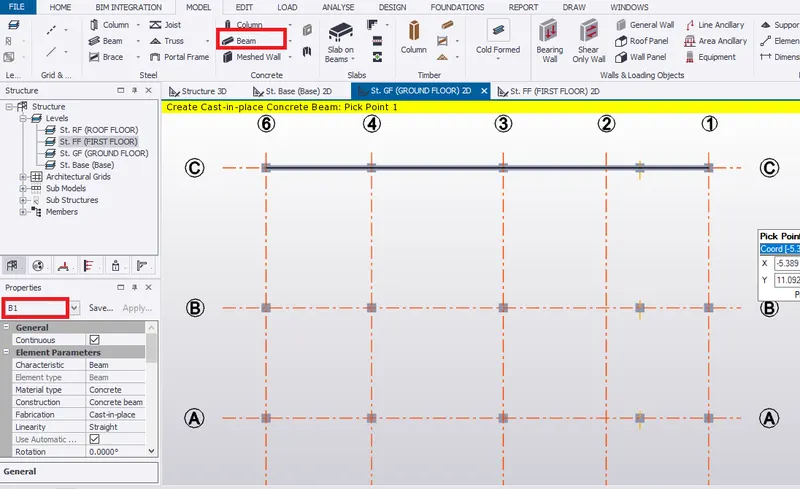
- Copy this beam to grid line B and A.
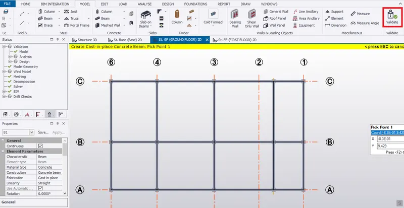
- Similarly, provide B1 beam along grid line 1,2,3,4, and 6.
- Therefore, no error after validation.
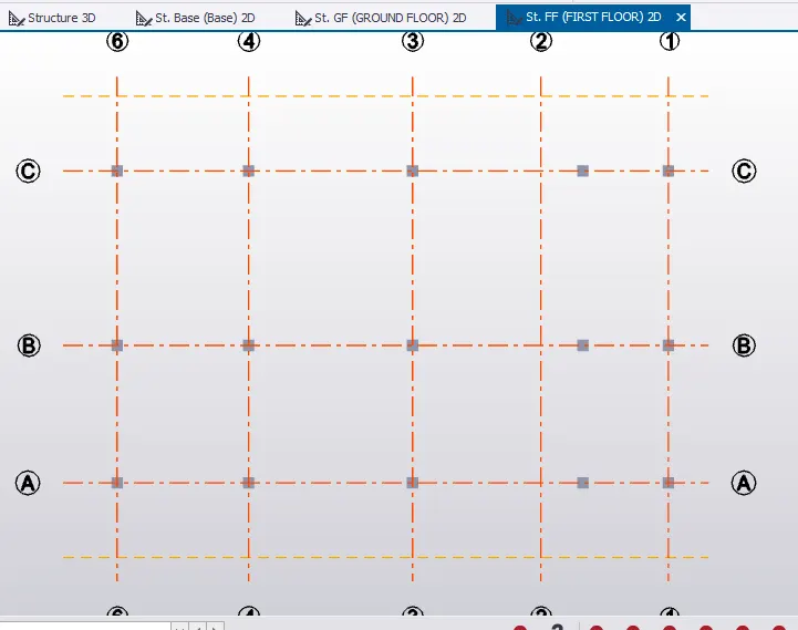
- Go to first floor in scene view, create parallel construction line at a distance 2.62m from grid line A and C for the corrider provision as shown in the attachment 2.1.
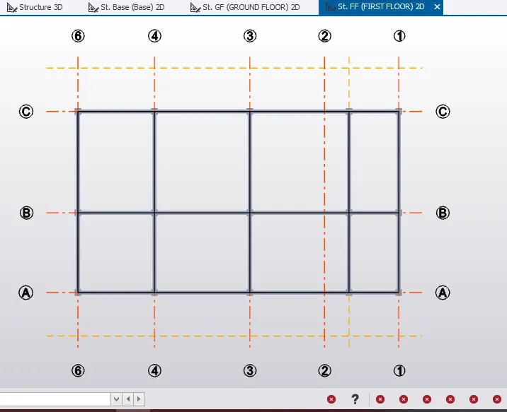
- In first floor, select concrete beam from Model tab.
- Under property window, select B1 continuous.
- Pick the point 1 to 5 to create the concrete beam.
- Copy this beam to grid line B and A.
- Similarly, provide B1 beam along grid line 1,2,3,4, and 6.
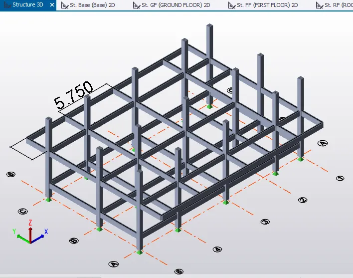
- For corrider, cantilever beams are to be provided.
- Go to manage property sets to create property for cantilever beam.
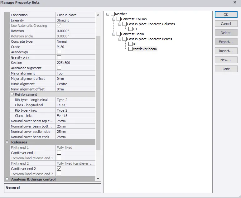
- Select concrete beam from model tab
- Select cantilever beam from property window, pick the first point to create cantilever beam.
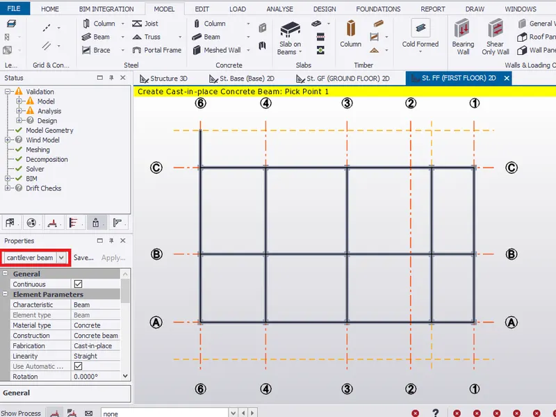
- Copy this cantilever beam to rest of the column ends as shown below for the corridor.
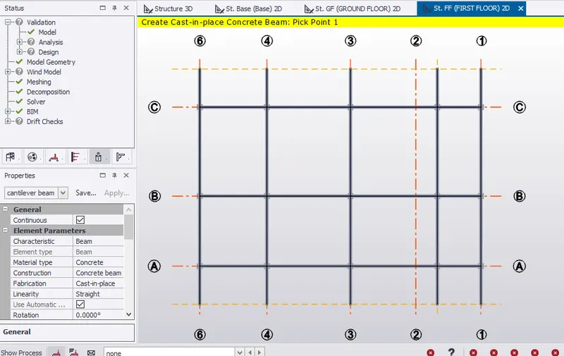
- Copy the B1 beam from grid line C and provide it at the cantilever ends.
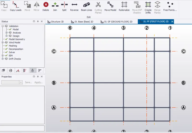
- Delete the beam from grid line B for the provision of staircase as shown in the first floor plan.
- Therefore, beam position in the first floor is shown below.

- Check in structural 3D view.
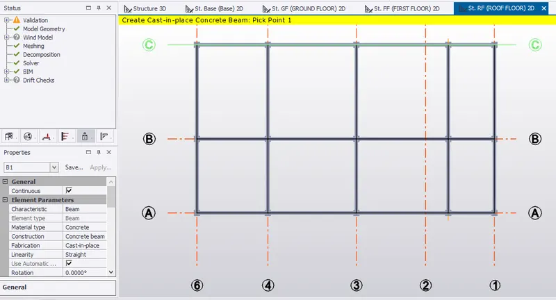
- In roof floor, select concrete beam from Model tab.
- Under property window, select B1 continuous.
- Pick the point 1 to 5 to create the concrete beam.
- Copy this beam to grid line B and A.
- Similarly, provide B1 beam along grid line 1,2,3,4, and 6.
Slab on Beam
- Go to manage property sets to set property for 2 way slab as shown below.
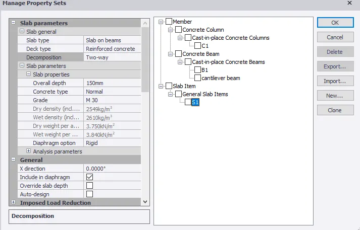
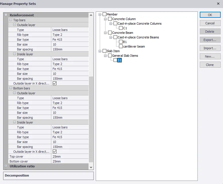
- Go to first floor in scene view, select slab on beams
- Change to S1 in property window.
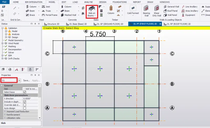
- Go to manage property sets to set property for 1 way slab as shown below since lx/ly >2.
- Provide reinforcement as provided in 2 way slab.
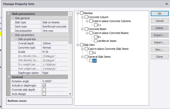
- Provide 1way slab for rest of the slab area. Avoid the staircase area.
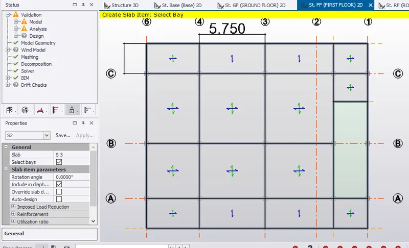
- Go to roof floor in scene view, select slab on beams from ribbon window.
- Change to S1 in property window for 2 way slab.
- Also, provide S2 for 2 way slab for region where lx/ly >2.
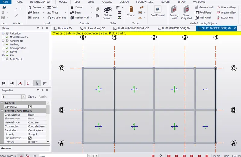
- Check in structural 3D view.
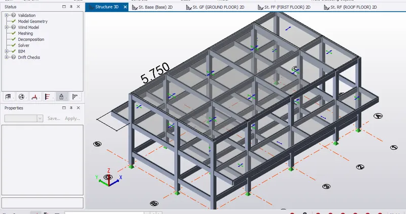
RESULT:- Hence, modelling of RCC columns, beams and slabs as per your general arrangement is completed.