To Design slab and foundation for an RC residential building using TSD
- Design the slab and foundation of the model. Outline the thought process for designing of the elements (column, beam, slab and foundations)
AIM:- To design the slabs and foundation for the model.
INTRODUCTION:- Slab design are done based on the dead load, live load and floor finishes and based on this slab thickness and reinforcement are provided. Similarly, foundation design is done based on the column load and soil type and based on that pile and pile cap are provided.
PROCEDURE:-
Slab design
- Go to first floor in scene view.
- In scene content, untick grid lines and members, so that only slab members can be seen.
- After run analysis, select slab 12 to check panel.
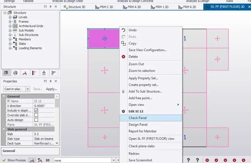
- Slab reinforcement does not satisfy the design criteria.
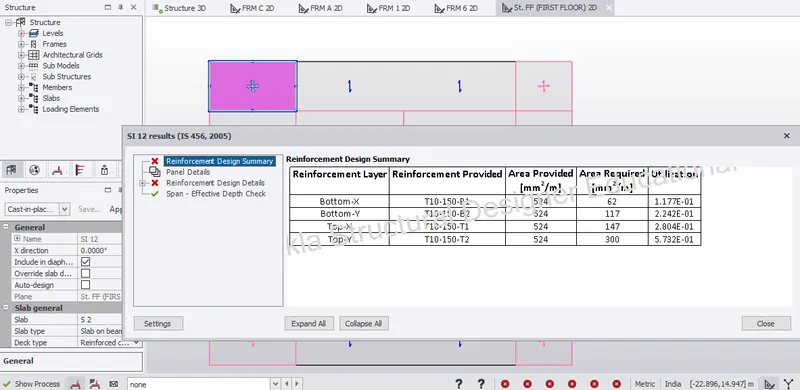
- As area of reinforcement provided is more than the area of reinforcement required, go to property window, change reinforcement spacing to 175mm for 10mm diameter bar.
- Once again check the panel. Hence, safe.
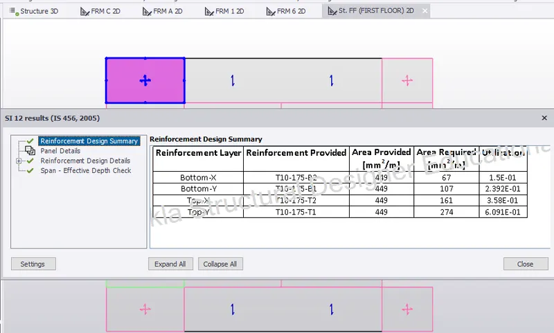
- Similarly, select the identical slab of SL12 (ie, SL21).
- In the property window, change the reinforcement spacing to 175 mm as provided for SL12.
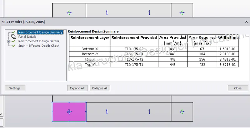
- Since the slab span size is high, either we provide higher slab depth or provide secondary beams in between to reduce the l/d ratio.
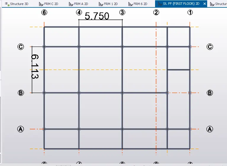
- Provide secondary beams between grid line A, B and C.
- Delete the slab portion and again provide slab on beam
- Apply dead and imposed load on the newly created slab.
- Validate the model to check any error.
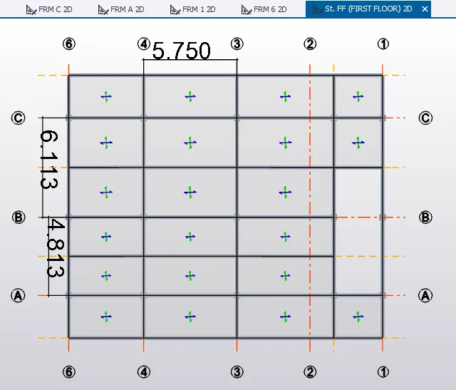
- Run analysis.
- Select the newly Created slab SL55 to check panel.
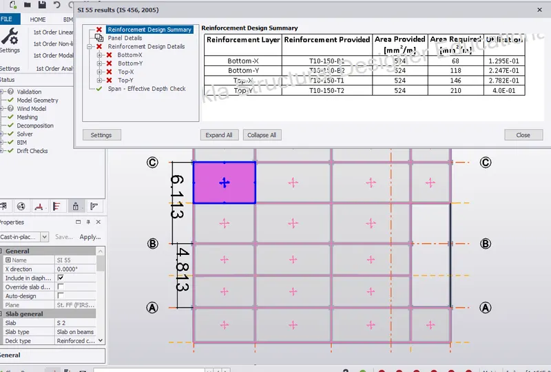
- Provide overall depth 150mm and reinforcement diameter of 10mm at 175mm centre to centre for SL55.
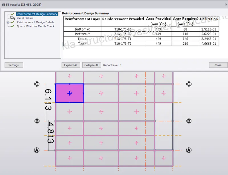
- Similarly, provide overall depth 150mm and reinforcement diameter of 10mm at 175mm centre to centre.
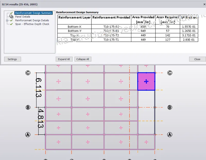 Slab 54 with Diameter 10mm at 175mm c/c
- Provide slab depth of 150mm with 10mm diameter at 175mm c/c thorough out.
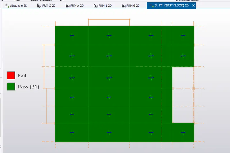
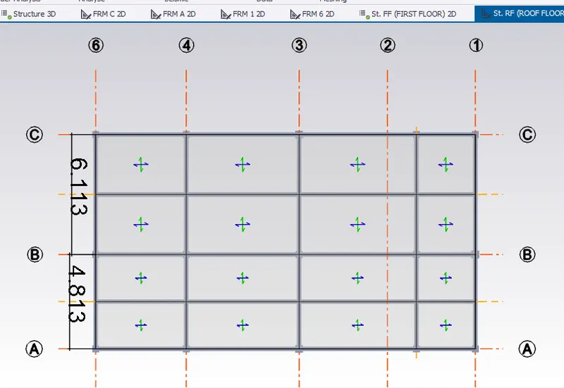
- For roof floor, provide secondary beams between grid line A, B and C.
- Delete the slab portion and again provide slab on beam
- Apply dead and imposed load on the newly created slab.
- Validate the model to check any error.
- Select SL 83. Provide depth of 150mm and reinforcement diameter 10mm at 175mm spacing.
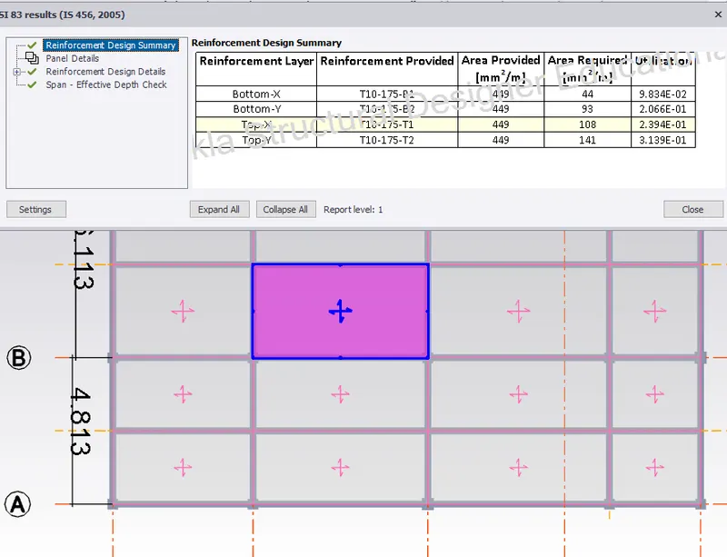
- Similarly, provide reinforcement diameter 10mm at 175mm spacing thorough out. Hence, safe
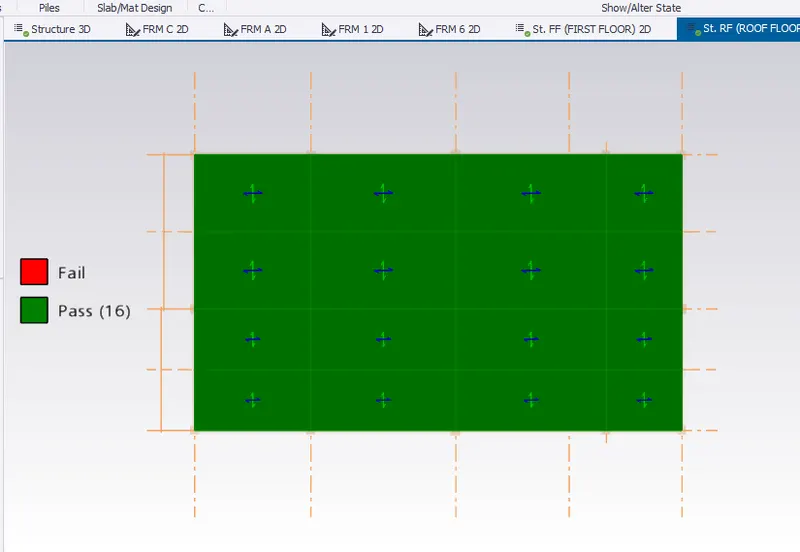
Foundation Design
- Go to settings, Under Isolated Foundation, select pile cap for reinforcement settings.
- Set minimum loose bars as 16mm diameter.
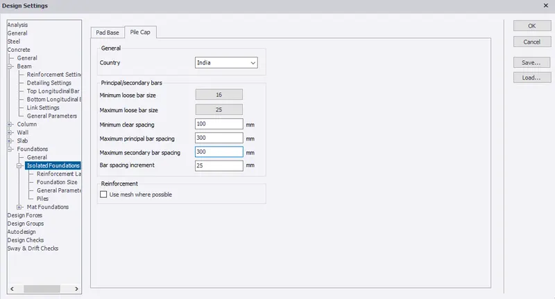
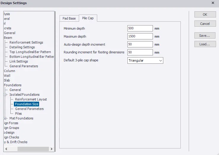
- Set pile cap size
- Set general parameter for pile cap.
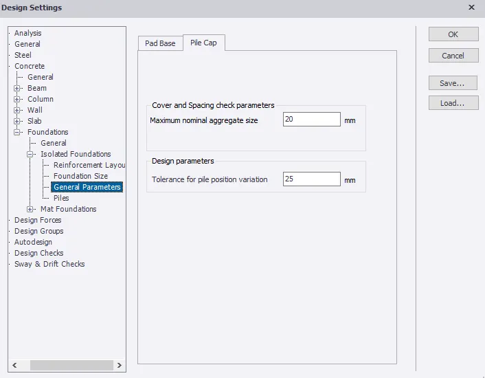
- Set general pile property.
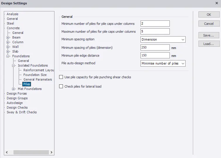
- Go to base floor, set pile type in catalogue.
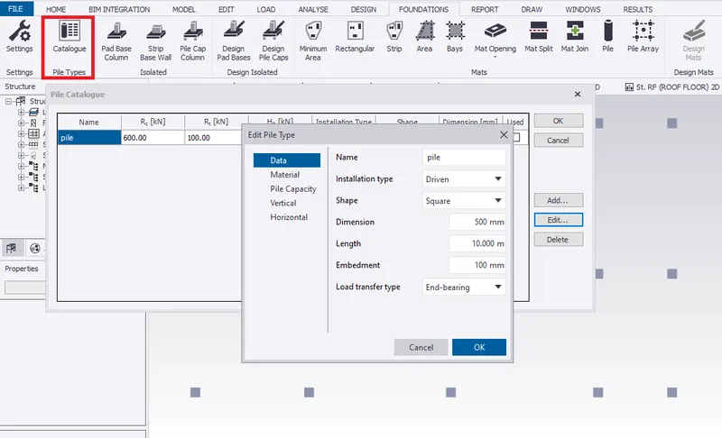
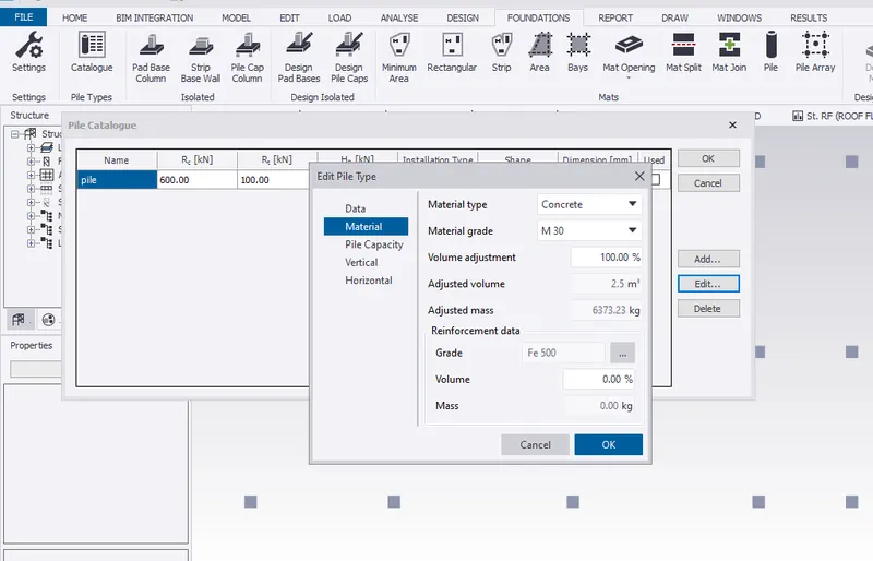
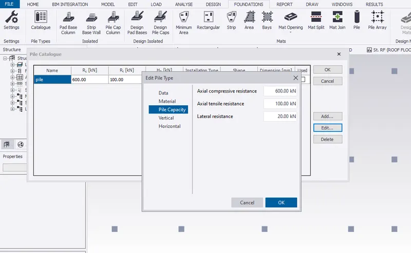
- Edit data, materials and pile capacity for piles.
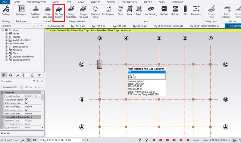
- Select isolated pile cap column
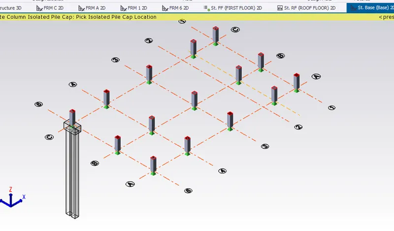
- Pick the location to create column isolated pile cap position.
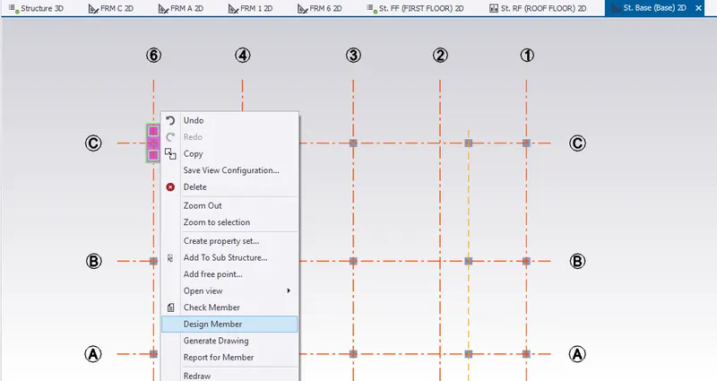
- Select to design the member.
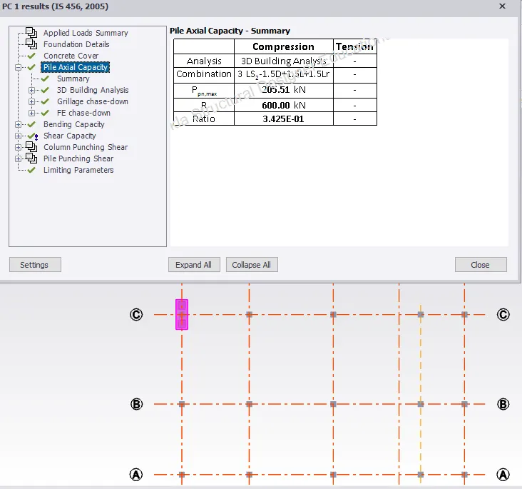
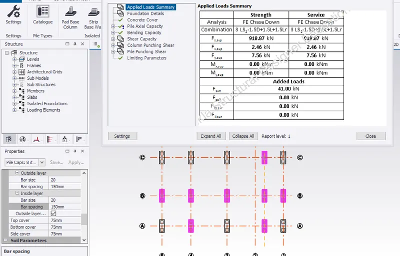
- In the property window, change the property for PC1 pile.
- Size 2.05m x 0.8m x1m. M30 grade of concrete
- Pile spacing= 1250mm with reinforcement diameter of 20mm at 150mm c/c spacing
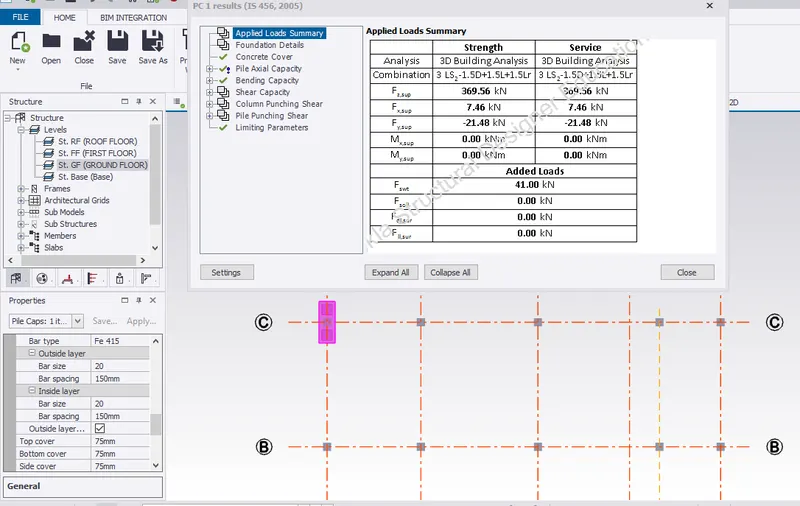
- Simiarly, select isolated pile cap column
- Pick the C2 location to create column isolated pile cap position.
- Design the member
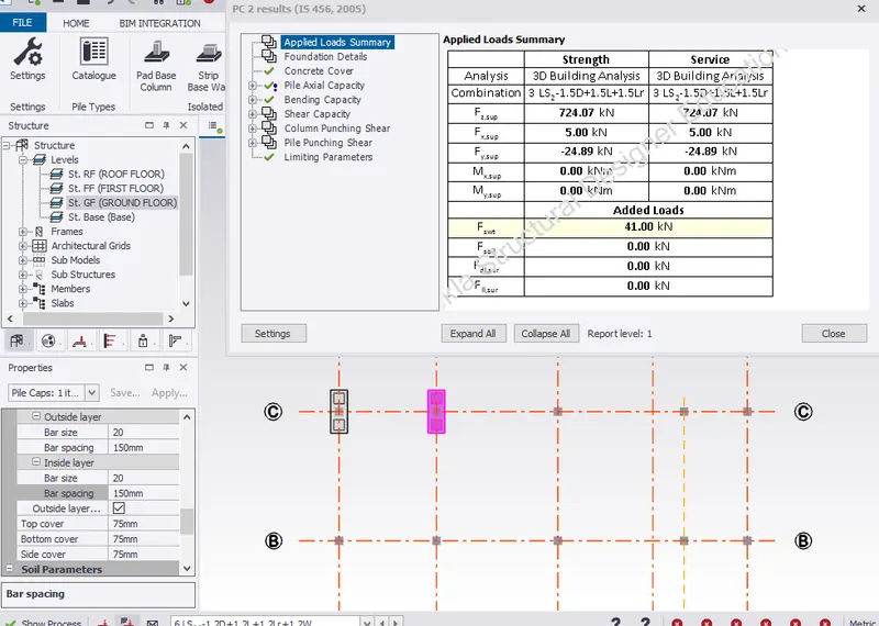
- In the property window, change the property for PC2 pile.
- Size 2.05m x 0.8m x1m. M30 grade of concrete for 2 pile
- Pile spacing= 1250mm with reinforcement diameter of 20mm at 150mm c/c spacing
- Check the member satisfy the design condition.
- Simiarly, select isolated pile cap column
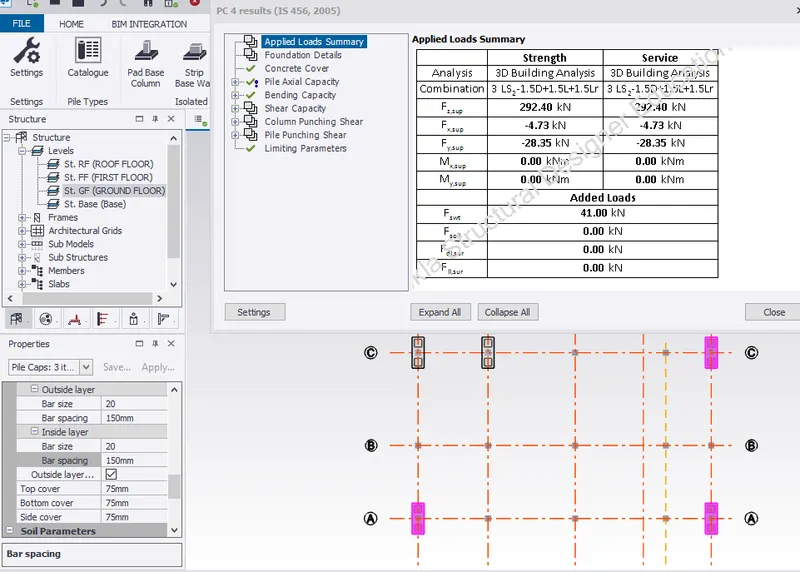
- Pick the C5,C11,C15 location to create column isolated pile cap position.
- In the property window, change the property for PC3,PC4,PC5 pile.
- Size 2.05m x 0.8m x1m. M30 grade of concrete for 2 pile
- Pile spacing= 1250mm with reinforcement diameter of 20mm at 150mm c/c spacing
- Check the member satisfy the design condition.
- Simiarly, select isolated pile cap column
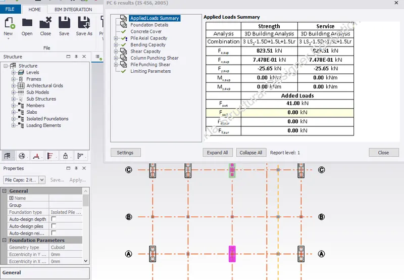
- Pick the C3,C13 location to create column isolated pile cap position.
- In the property window, change the property for PC6,PC7 pile.
- Size 2.05m x 0.8m x1m. M30 grade of concrete for 2 pile
- Pile spacing= 1250mm with reinforcement diameter of 20mm at 150mm c/c spacing
- Check the member satisfy the design condition.
- Simiarly, select isolated pile cap column from ribbion tan
- Pick the column location to create column isolated pile cap position.
- In the property window, change the property for pile.
- Size 2.05m x 0.8m x1m. M30 grade of concrete for 2 pile
- Pile spacing= 1250mm with reinforcement diameter of 20mm at 150mm c/c spacing
- Check the member satisfy the design condition.
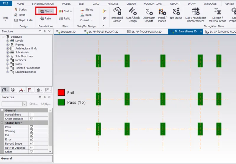
- In review view, check the status of the pile cap.
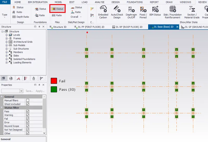
- Also, check status of pile in review view. Hence safe.
Outline for designing the member elements
- Column and beams are designed by interactive design method.
- Column of particular frame is selected. each stacks are provided with required reinforcement for section members. The UR value should be less than 1.
- Beam of a particular floor is selected with maximum bending moment. Tension and compression bars are provided at needed arrangement. Stirups are provided to resist shear force. UR value should be less than 1.
- Slab panels are checked and based on the load, slab thickness and reinforcement at required spacing are provided. Also, l/d value should be less than 1.
- Based on the geotechnical report and soil capacity, pile and pile cap designing must be done. Set details of pile in pile catalog for design the pile.
RESULT:- Hence, designed slab and foundation for the model.