To model beams and bracings for industrial steel structures using TSD
- Create beam properties for First floor and model the beams
AIM:- To create beam properties for First floor and model the beams
INTRODUCTION:- Beam are provided to carry slab loads of that particular floor, ie, beams in the first floor takes the slab load that is placed above it. Tekla Structural Design is used to model, analysis and design of beams in a structural building.
PROCEDURE:-
- Open the file that was previously modelled for columns, primary beams and secondary beams in ground floor.
- In project workspace, under LEVEL, select FIRST FLOOR.
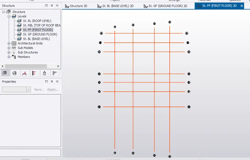
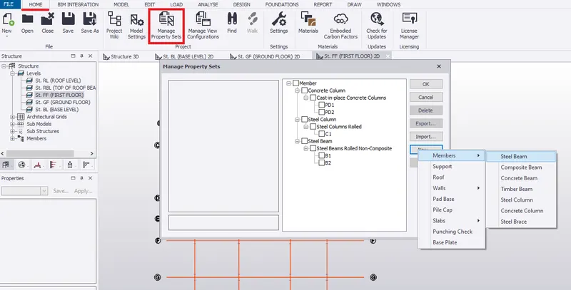
- To create beam property, go to HOME, select MANAGE PROPERTY SETS.
- Under MANAGE PROPERTY SETS, select NEW and then select STEEL BEAMS.
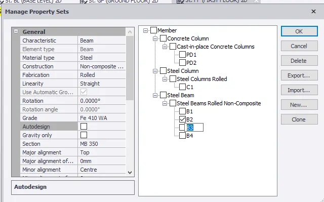
- Rename Steel Beam Rolled Non-Composite to B3
- Set grade of steel as Fe 410 WA, steel section as ISMB 350 and major alignment as TOP.
- Turn off AUTO DESIGN. Click OK.
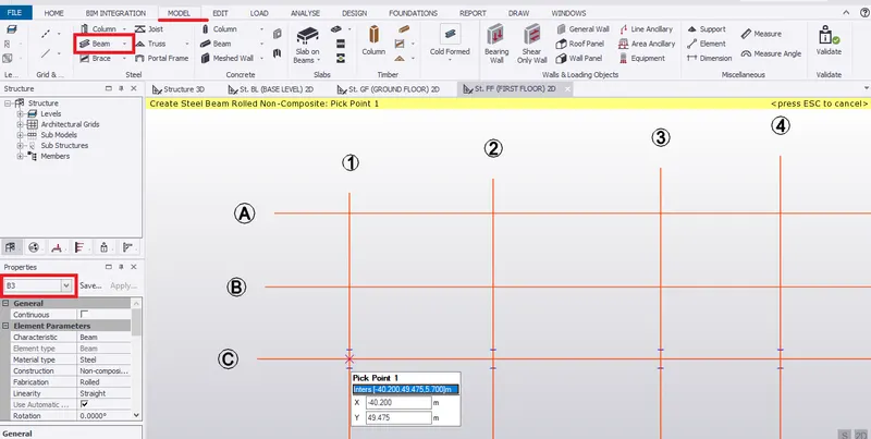
- Go to MODEL, select BEAM under steel section.
- Under property window, select B3 member and check the properties of B3.
- Pick point 1 on grid line C-1 and then point 2 on grid line C-2 to create a beam.
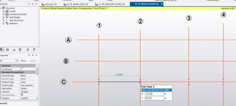
- Therefore, a beam is created on grid line C as per requirement.
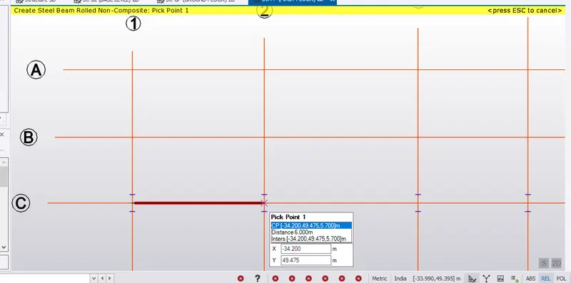
- Similarly, create beams by picking point on C2, C3 and C4.
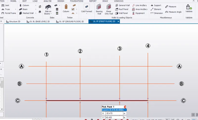
- Similarly, create beams by picking point from column to column.
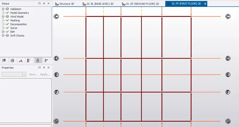
- Therefore, primary beam is created in first floor as shown below.
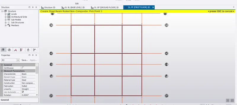
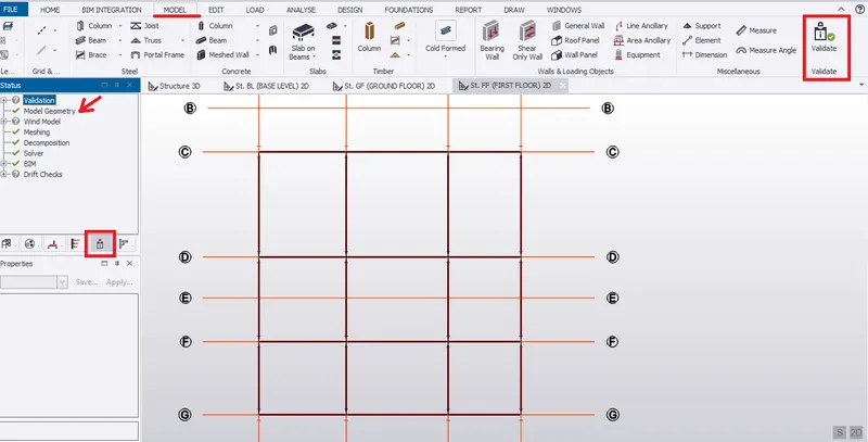
- Go to MODEL tab, click on VALIDATE to check if there is any error on the model creation.
- In project window, under statues it is shown that model geometry has no error.
- As per first floor plan, a staircase portion comes between grid line C and D and also between 1 and 2.
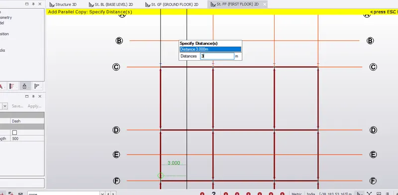
- To create staircase beam, firstly, construct a parallel construction line which is 3m from grid line 1.
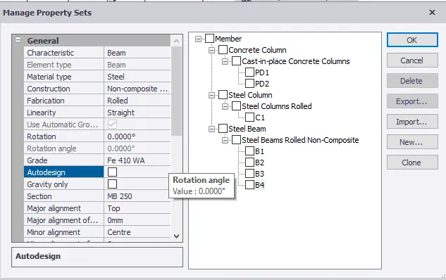
- Go to HOME, select MANAGE PROPERTY SETS.
- Select MEMBERS, then STEEL BEAM.
- Name B4. Set steel section as ISMB 250 for staircase beam.
- Go to MODEL, select Beam in steel section.
- Set to B4 beam in the property window.
- Pick point 1 which 3m from the primary beam.
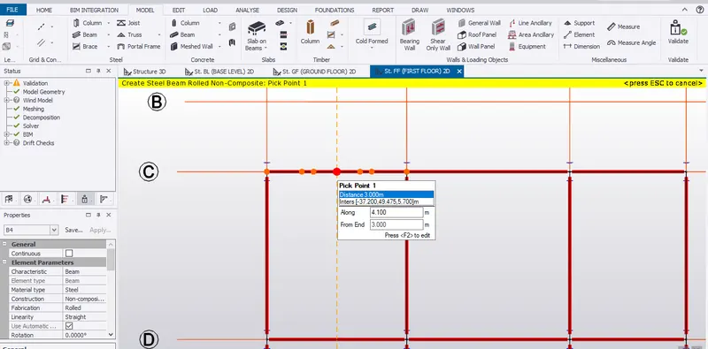
- From point 1 drag to pick point 2 to form beam for staircase.
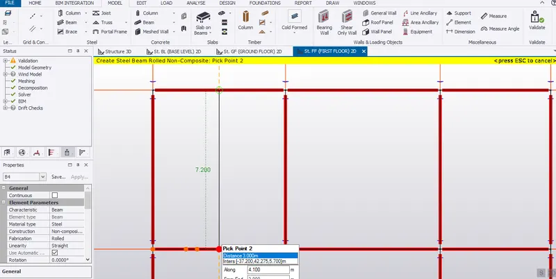
- Since the span length for toilet area is large, we will provide secondary beam along the mid span as shown below.
- Set to B4. Pick the first point on the primary beam which is 3m.
- Similarly, create an another secondary beam for second toilet area.
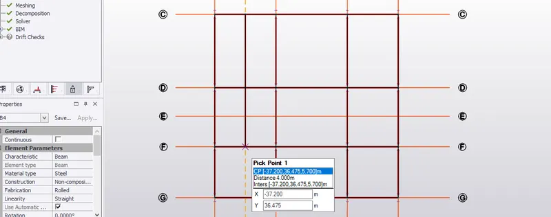 SECONDARY BEAM FOR FIRST TOILET AREA
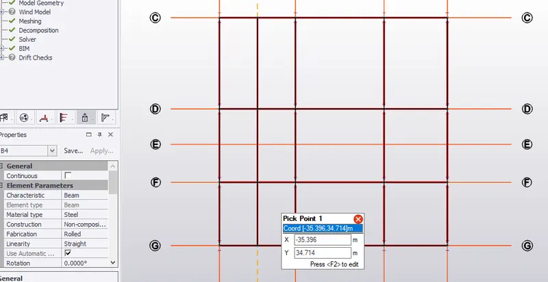 SECONDARY BEAM FOR SECOND TOILET AREA
- Construct a parallel construction line which is 3.5m from grid line 2 since the span length of beam between 2 and 3 grid line is large.
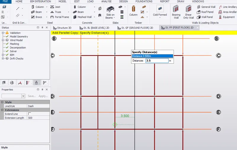
- Pick the first point on the construction line and drag to pick down to pick second point.
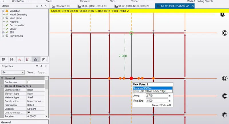
- Similarly, create secondary beam to reduce the span size of the primary beam.
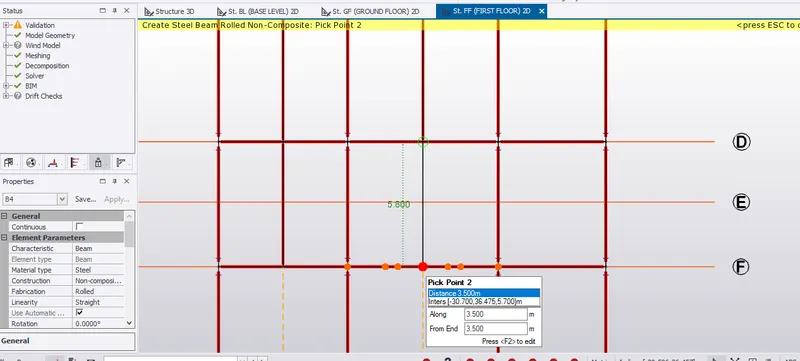
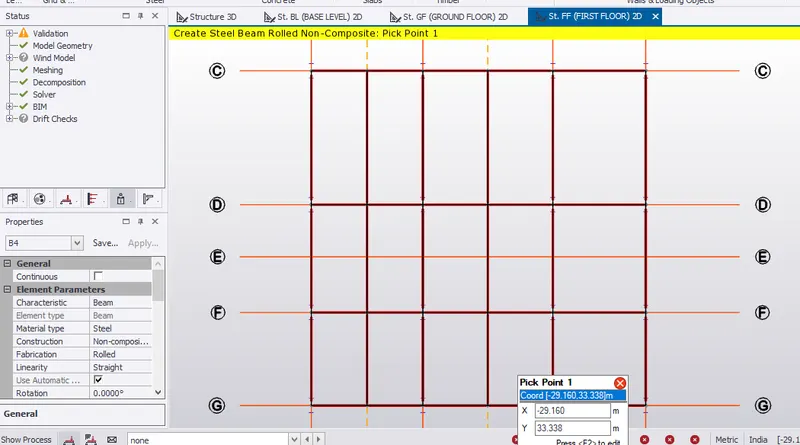
- Validate the model created to check any error.
RESULT:- Beam properties and modelling of beams in the first floor is completed. Therefore, from validation no error in geometry modelling.
II. Create rafter beam on second floor as roof and moment frame action in one direction and add bracings at locations as per the design intent
AIM:- To create rafter beam on the second floor as roof and moment action in one direction and add bracings at locations as per the design intent.
INTRODUCTION:- Rafter beams are long beams which are provided to parallel to roof sheets inorder to carry the sheet load. It is provided between the columns, where rafter beams are supported by columns.
In Moment Frames, building/structures are divided into frames where frames are modelled in such a manner to resist lateral loads(ie, wind load, seismic loads, etc.).
Bracing techinques are provided to resist sway action or provides lateral stabillity to the structure that takes place in a building which are provided on the sides of the building and on the roof.
PROCEDURE:-
RAFTER BEAM
- Create beams in the second floor/ top of roof beam level which is 12m from ground level.
- In project window, under LEVELS, select top of roof beam level.
- Go to HOME, select MANAGE PROPERTY SETS.
- Select STEEL BEAMS in MEMBERS. Name it to B5 to create top roof beam.
- Set grade of steel to Fe410 WA, section to ISMB 350. Turn off Auto Design.
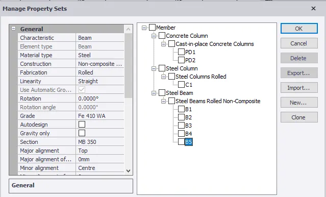
- Go to MODEL, select BEAM under steel section.
- Select B5 beam in property window.
- Create primary beam as shown below.
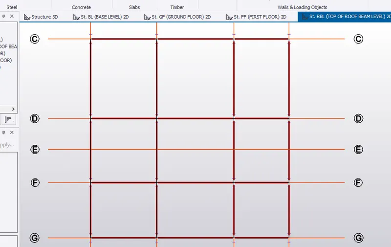
- Validate to check any error. Therefore, no error in model geometry.
- Go to 3D view in scene view.
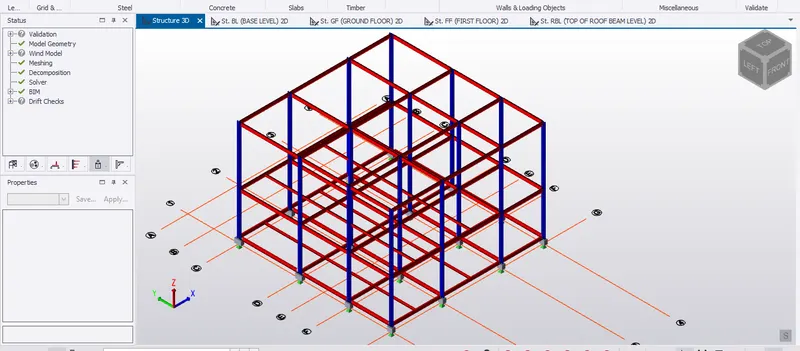
- To create frames, click on MODEL tab select FRAMES under ribbon tab.
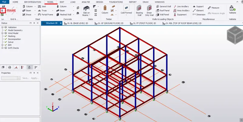
- To create frames, pick each grid lines.
- For example, let's pick grid line C.
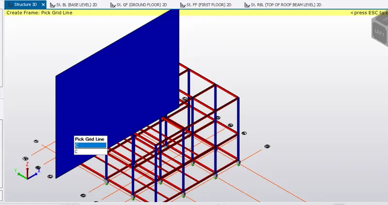
- Therefore, frame C created is shown in project window under project icon as shown below.
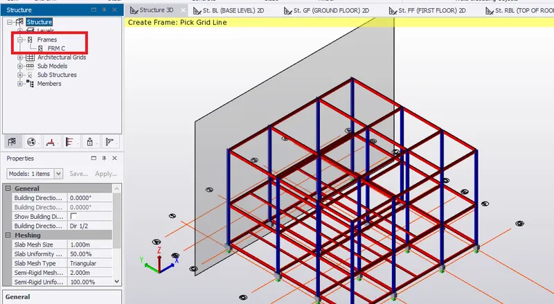
- Similarly, create frames D,F,G,1, 2, 3 and 4.
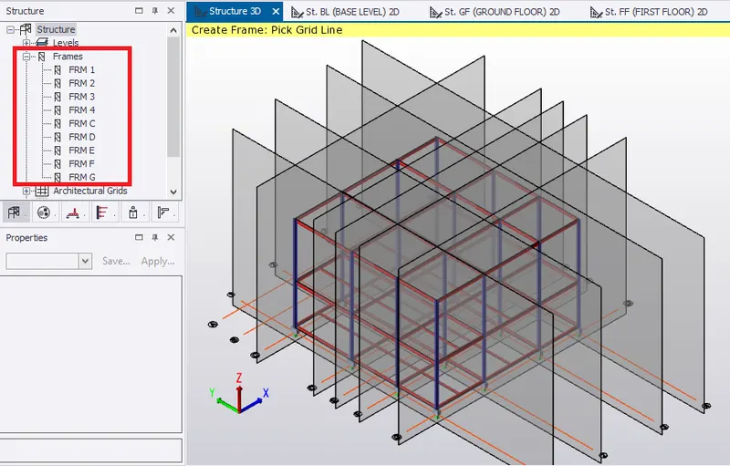
- Select frame 1 from project window. Therefore, frame 1 appears on the scene view.
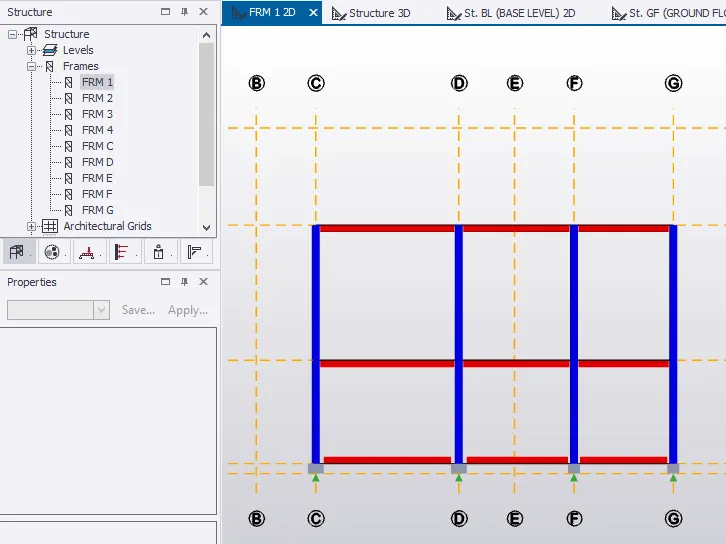
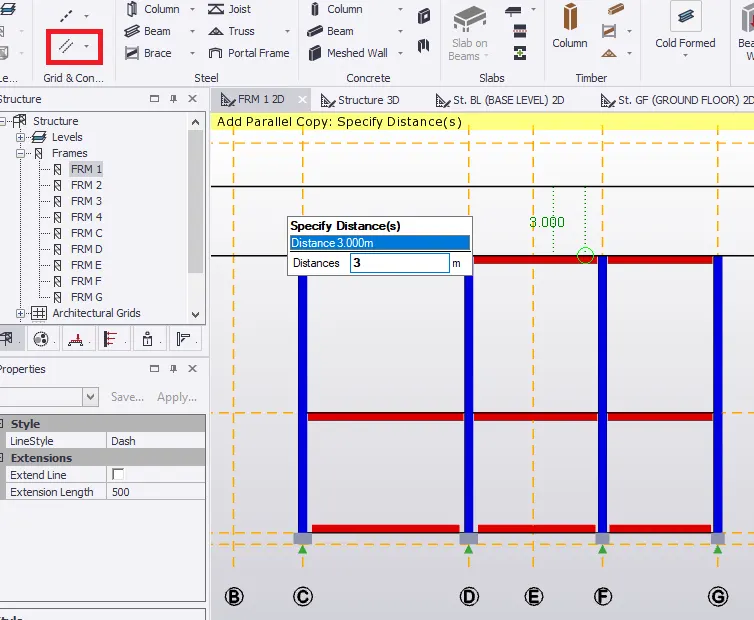
- Create a parallel construction line at 3m from top of roof beam to create reference line for rafter beam.
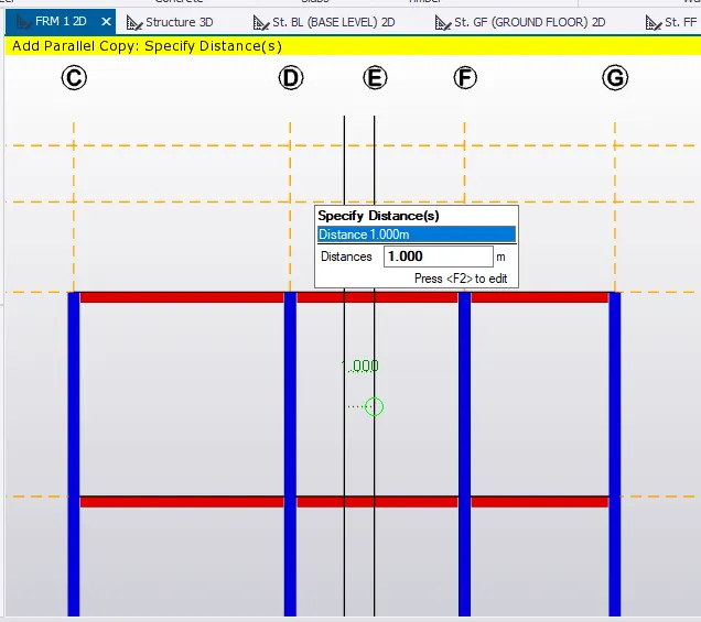
- Similarly, create a parallel construction line at 1m from left of grid line E to create mid-point for the sloping roof.
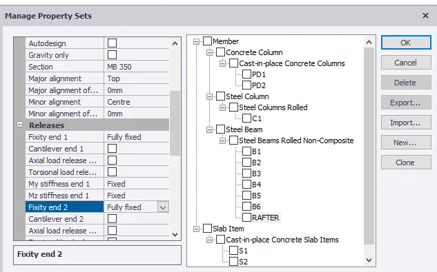
- Go to HOME, select MANAGE PROPERTY SETS.
- To set property for rafter beam, select MEMBERS from NEW and then STEEL BEAM.
- Name steel beam as Rafter and set member section to ISMB 350.
- In releases, end fixity is fully fixed at both ends. Click ok.
- Go to MODEL, select BEAM from steel section. Set to Rafter beam in property window.
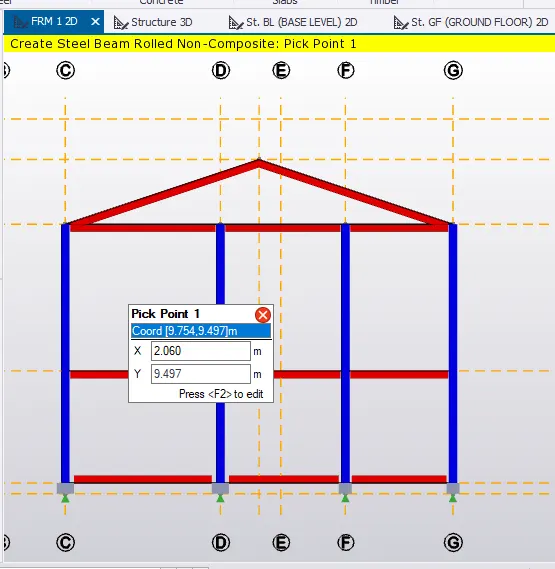
- Pick the first point on the top of roof beam at grid line C.
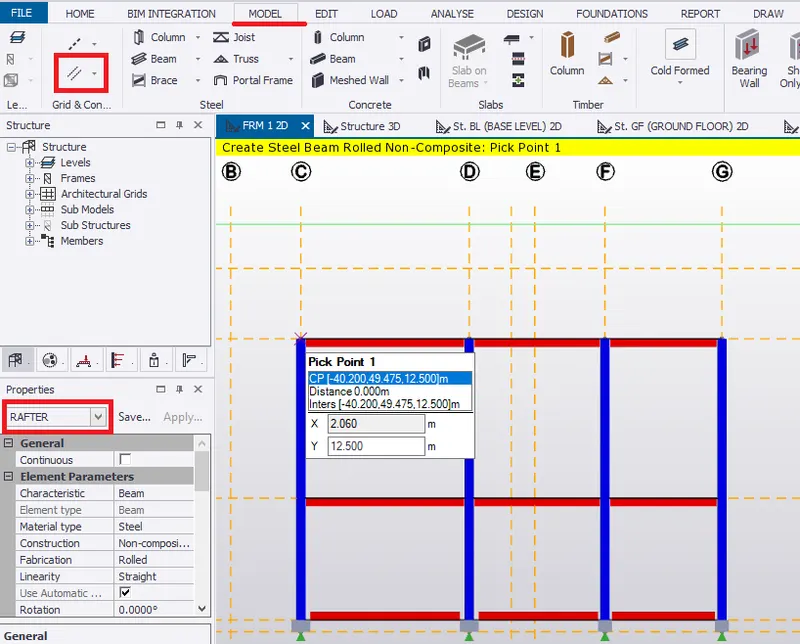
- From first point to reference line (construction line) to form rafter beam. Similarly, pick a point on grid line G on top of roof beam to the reference line.
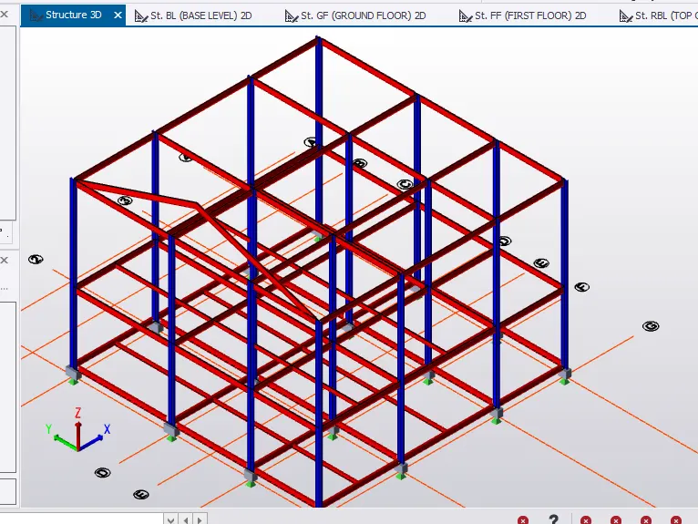
- See in 3D view as shown below.
- Select the rafter beams and copy the rafter beams to remaining column points.
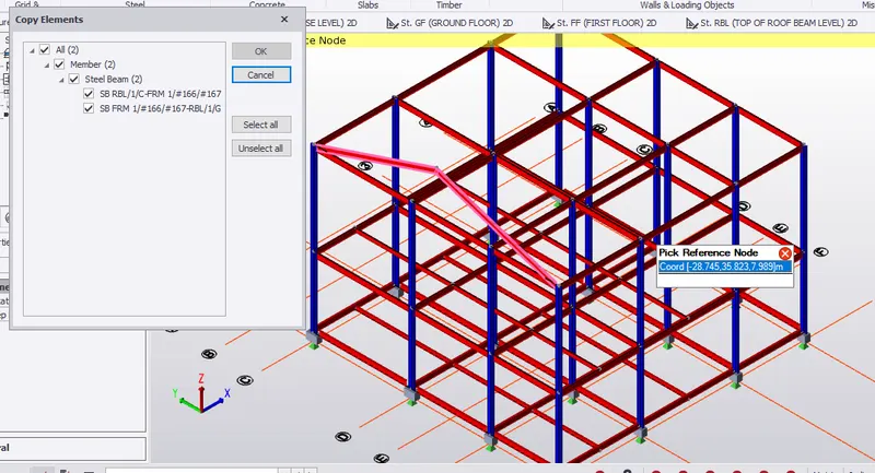
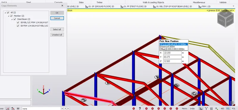
- Pick the reference node of the rafter beam and pick the column point of the new position of the copy rafter beam.
- To provide beams on ridgeS on the roof.
- Go to MANAGE PROPERTY SETS. Select STEEL BEAMS and name it to RIDGES.
- Set to ISMB 250. Click ok.
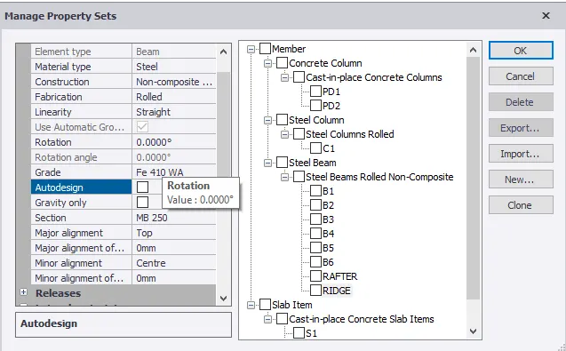
- Select BEAM in the MODEL tab. Set to RIDGE in the property window.
- Pick first point on the apex the the rafter beam and move to pick the second point of the next rafter beam. Similarly, create ridges by picking apex point.
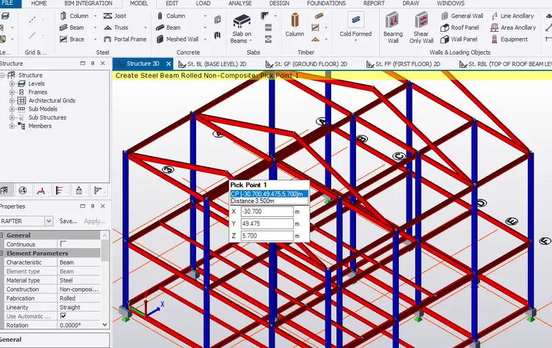
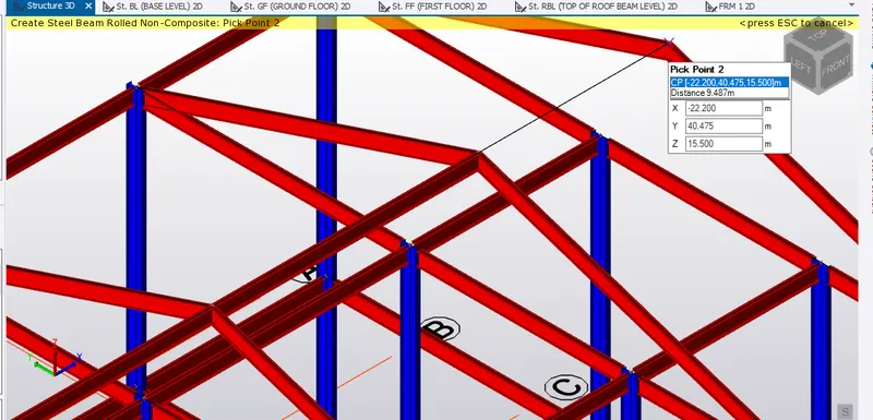
FIRST POINT ON THE APEX OF RAFTER SECOND POINT ON THE APEX OF RAFTER
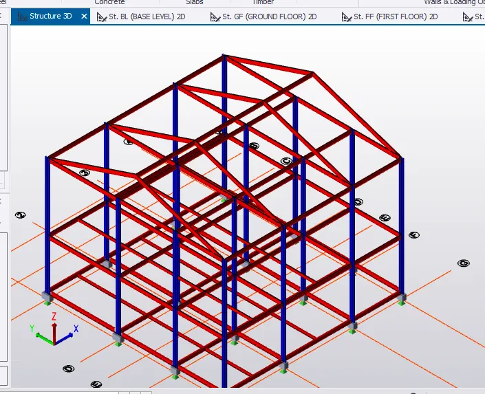 3D VIEW AFTER CREATING RAFTER
- Validate the model. Hence, no error found.
SLAB ON BEAM
- Go to first floor in the scene view to create slabs on beam.
- Go to HOME, select MANAGE PROPERTY SETS, then NEW and then GENERAL SLAB ITEM.
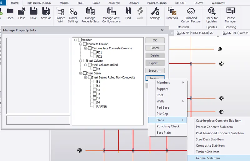
- Name slab to S1.
- Slect slab type as SLAB ON BEAM
- set to slab parameters to one- way, overall depth to 200mm and grade of concrete to M25.
- Set both top and bottom reinforcement to Fe 415 grade, bar size to 10mm and bar spacing to 150mm.
- Set slab cover to 30mm. Turn off Auto Design.
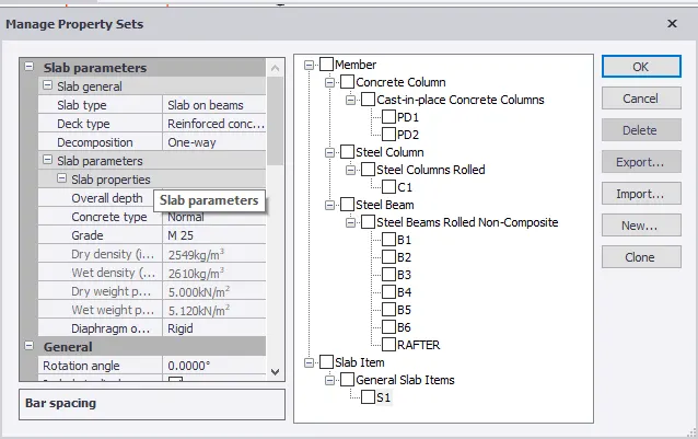
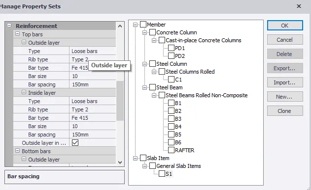
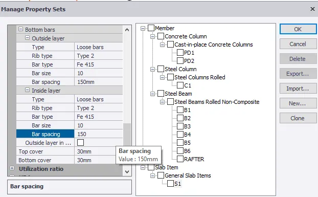 MANAGE PROPERTY FOR SLAB ON BEAM- S1
- Since span size is large, provide secondary beams between grid line 3 and 4.
- Go to MODEL, select SLAB ON BEAM.
- Set to S1. Select the bay to create 1- way slab item .
- Following slabs selected are one way slab.
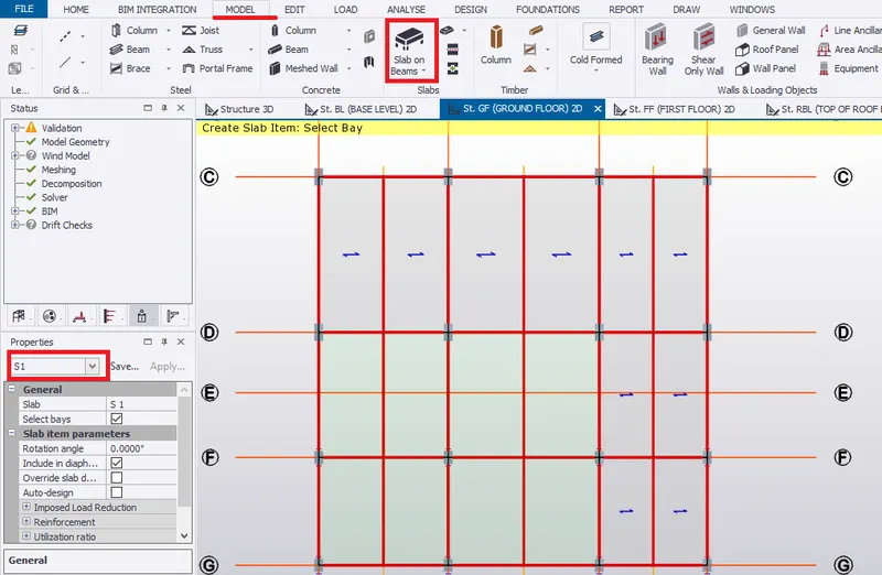
- To create properties for 2 way slab.
- Go to manage property sets. Select general slab item and name to S2.
- Set parameters to Slab on Beam and to 2- way slab.
- Also, set following general and reinforcement parameters as per slab S1.
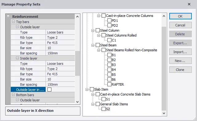
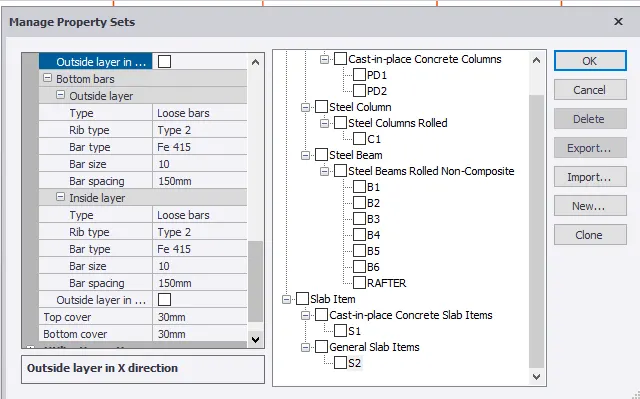 MANAGE PROPERTY FOR SLAB ON BEAM- S2
- Select slab bay for 2-way slab where lx/ly<2.
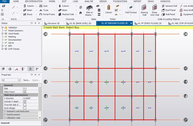 1- WAY AND 2-WAY SLAB IN GROUND FLOOR
- Similarly, select bays in first floor for 1-way and 2-way slab.
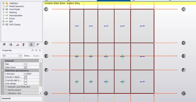 1- WAY AND 2-WAY SLAB IN FIRST FLOOR
- Similarly, for top roof beam/second floor for 2-way slab.
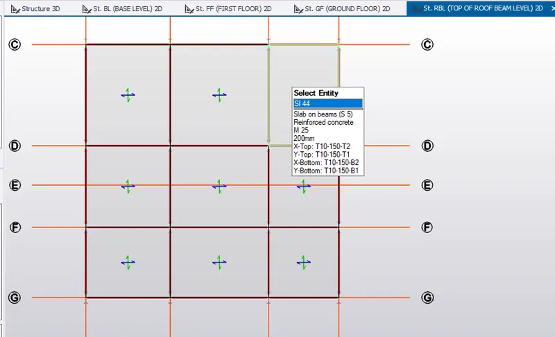 2-WAY SLAB FOR SECOND FLOOR
- Validate the model. Hence, no error in geometry model.
STEEL BRACING
- Go to MANAGE PROPERTY SETS, select STEEL BRACING in MEMBERS.
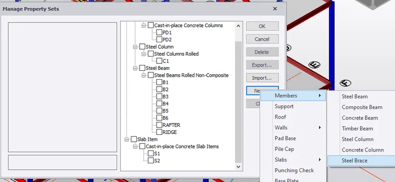
- Set grade of steel to Fe 410, section to equal angle ISA 75x75x8 and connections to BOLTED.
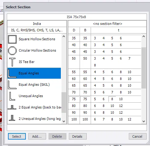
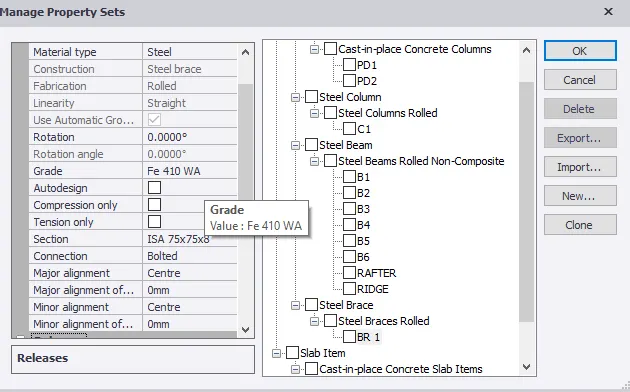
- In property window, select frame G
- For providing bracing, go to MODEL, select X- bracing.
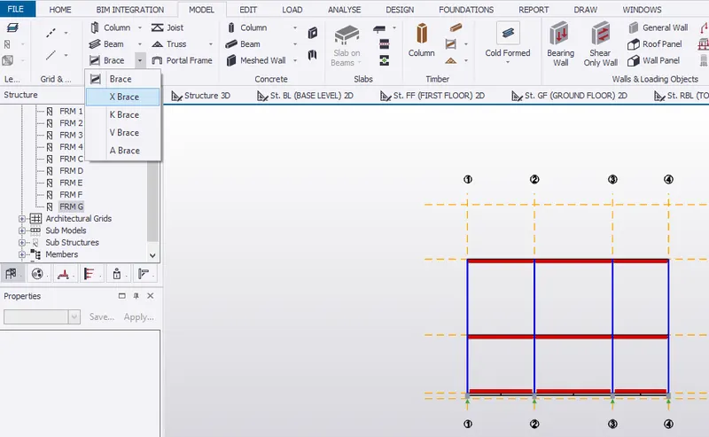
- Set to BR1 in property window.
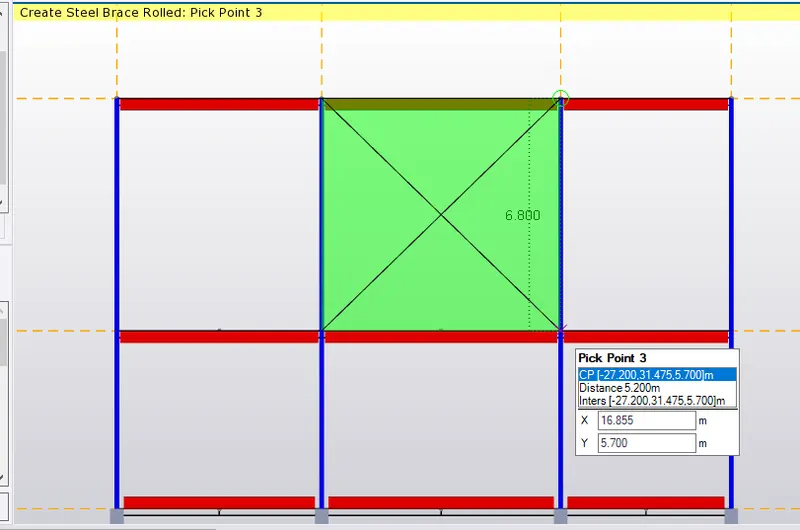
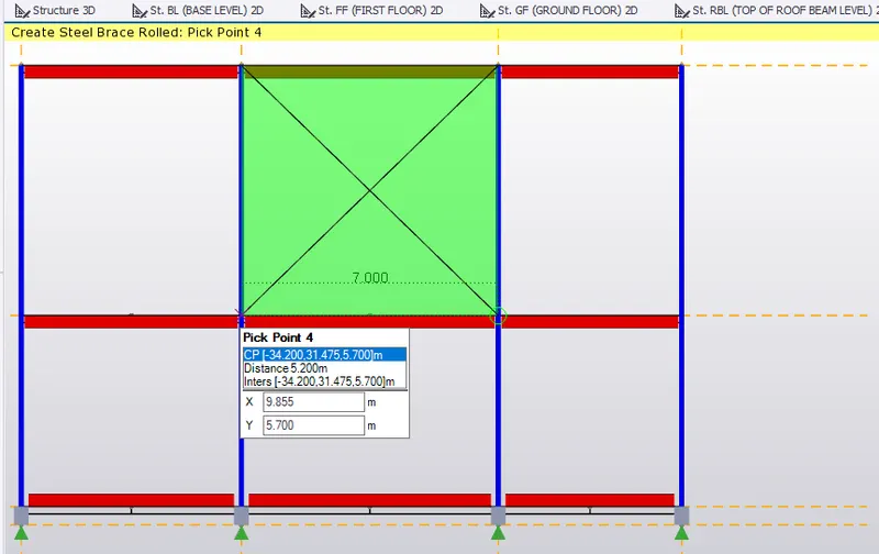
- To create X- bracing pick point 1,2, 3 and 4 respectively as shown below.
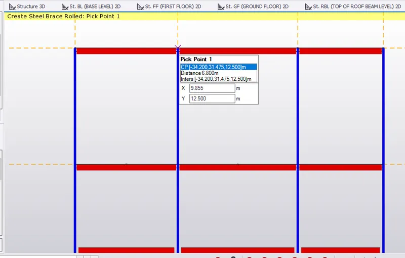
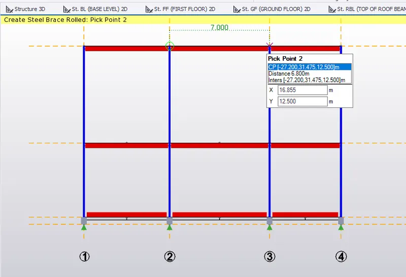
- Similarly, create bracing below the created bracing as shown.
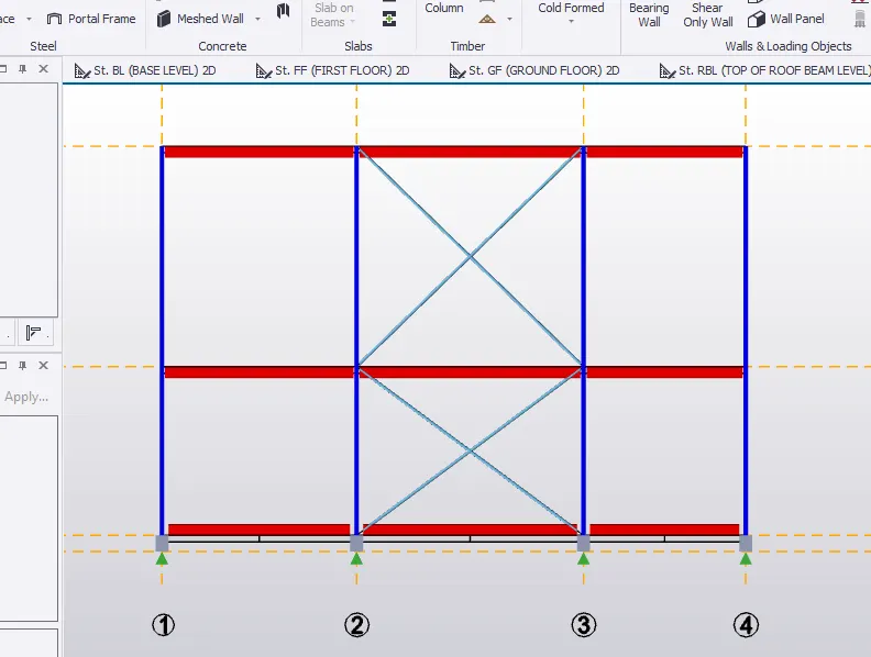
- Create bracing on the opposite side of structure.
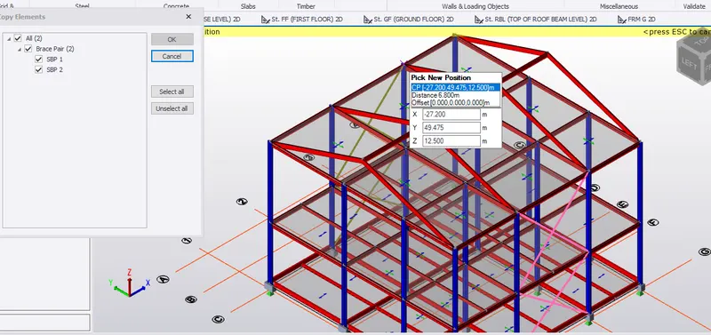
- Select the bracing created and copy to the required new position as shown below.
- To create bracing on the roof.
- Go to MANAGE PROPERTY SETS, select steel bracing. Name to BR2.
- Set steel section property to ISA 75x75x8 and connection to BOLTED.
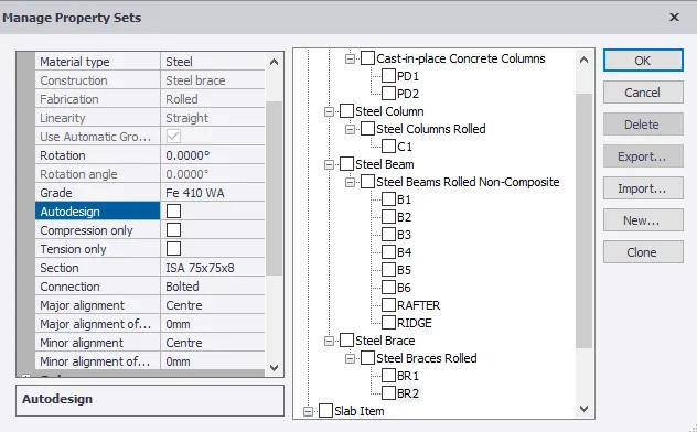
- Go to MODEL, select BRACING.
- Set to BR2 in property window.
- To create bracing, pick a point (mid-point) on the rafter as shown below.
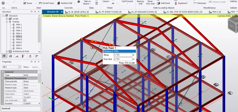
- To provide X- bracing, pick 4 corners as previously done for X- bracing.
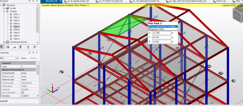
- Similarly, create bracing below.
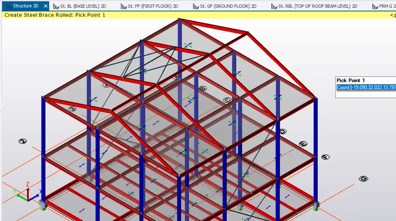
- Similarly, create bracing on the opposite roof portion by following the same procedure.
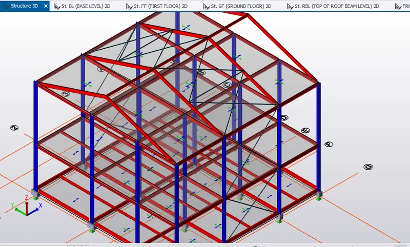
To create wall panels
- select frame G from the project window.
- Select WALL PANEL from ribbon tab under MODEL tab.
- Pick the corner points to create wind wall.
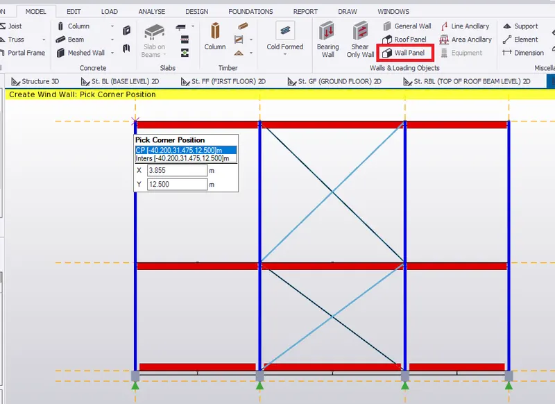
- Pick the opposite corners to create wall panel as shown below.
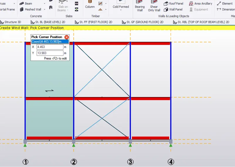
- Similarly, create wall panels for remaining two walls.
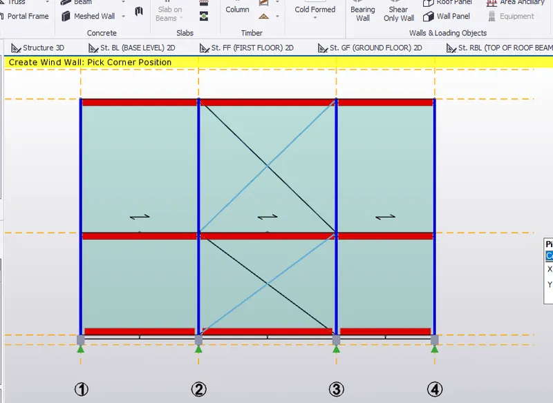
- Select the created wall panel and copy it to the opposite outer wall.
- Pick the reference point of the selected wall panel and paste it to new position.
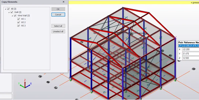
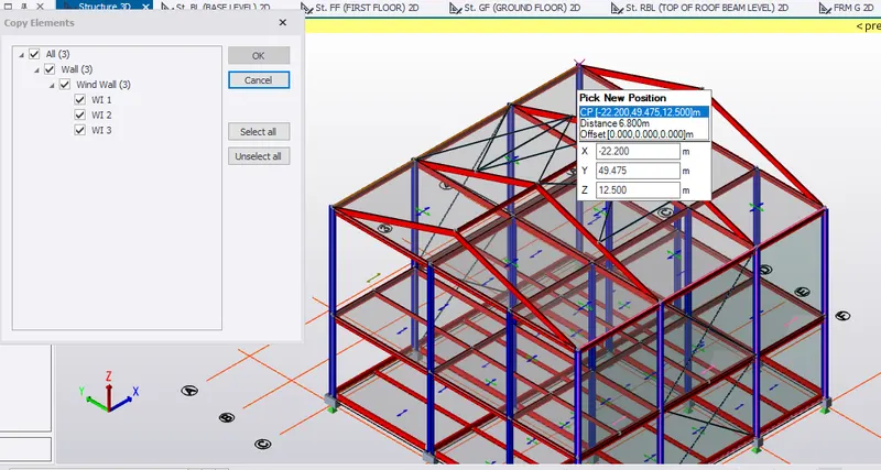
- To create roof panel, select roof panel from ribbon tab.
- Pick point 1 of the roof corner to create panel.
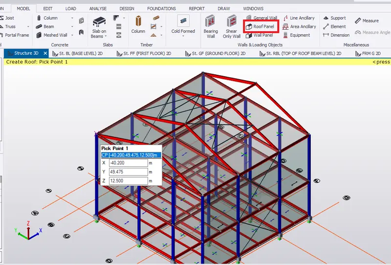
- Simultaneously, pick all 4 corners to create a roof panel as shown below.
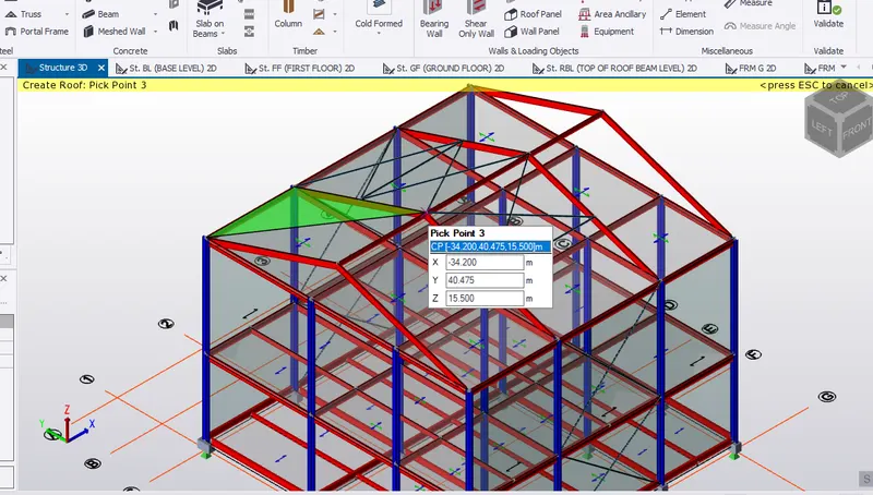
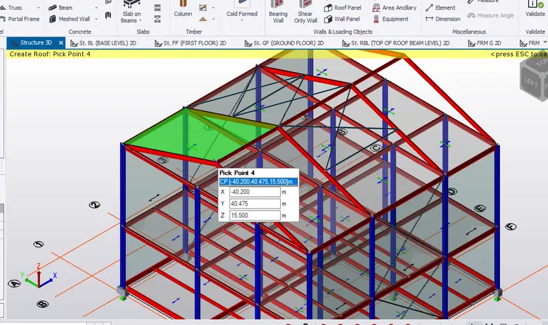
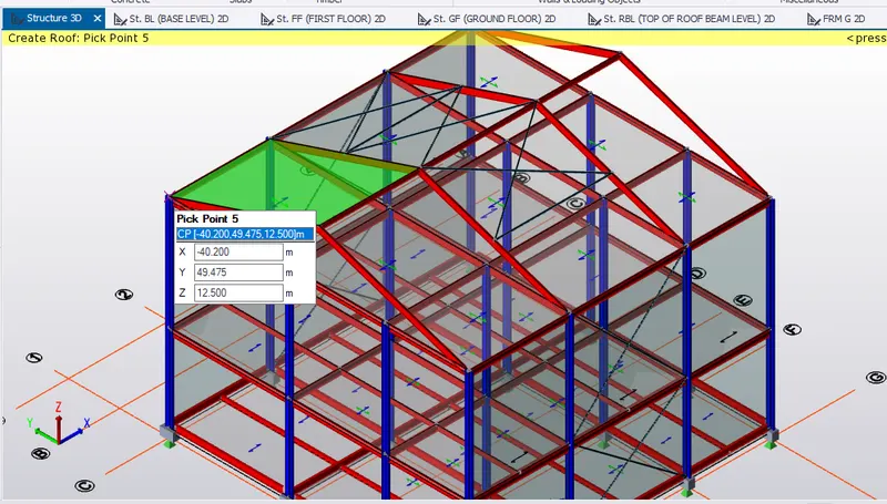
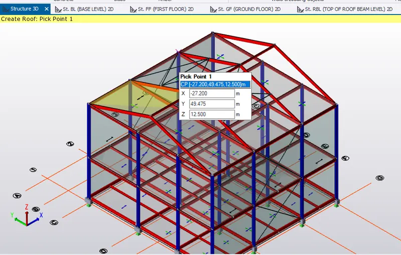
- Similarly, create roof panel for the rest of the roof.
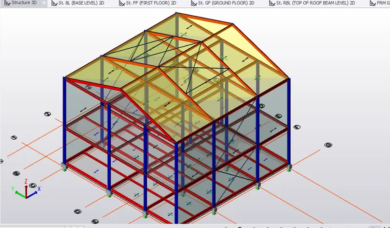
- Hence, roof panel is created.
- Validate the model. Hence, no error in the model geometry.
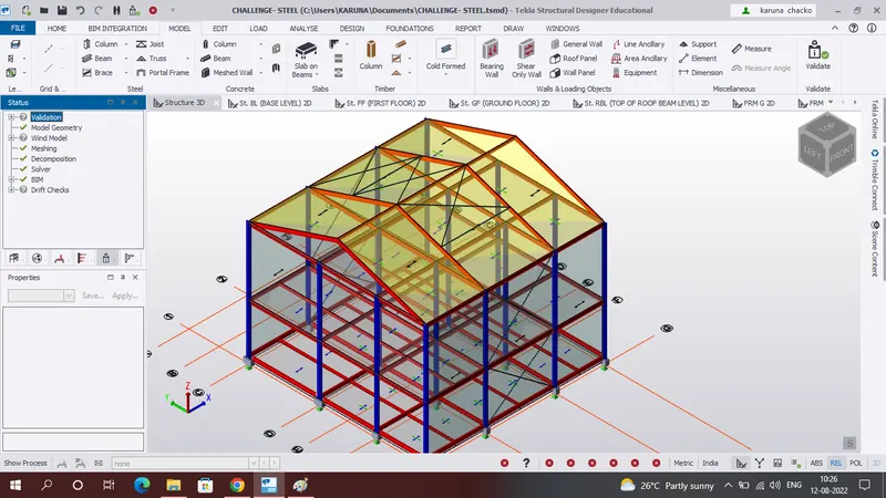
RESULT:- Therefore, created rafter beam on second floor as roof. Also, created moment frame action in one direction and provided bracings at locations as design intent