To plan a structural layout and to create grids using TSD
To plan a structural layout and to create grids using TSD
PART 1
AIM: To Summarize the user interface in TSD with the for the following items: -
- Project Workspace – How to access and usage
- Scene Content – Demonstrate the use of scene content
- Create two scene views
- Loading drop list- How to access
- Properties windows – how to access and usage
1.Project Workspace:
Initially open the Tekla Structural Designer software and the software will open as follows.
Now click on New option to create a new model workspace.
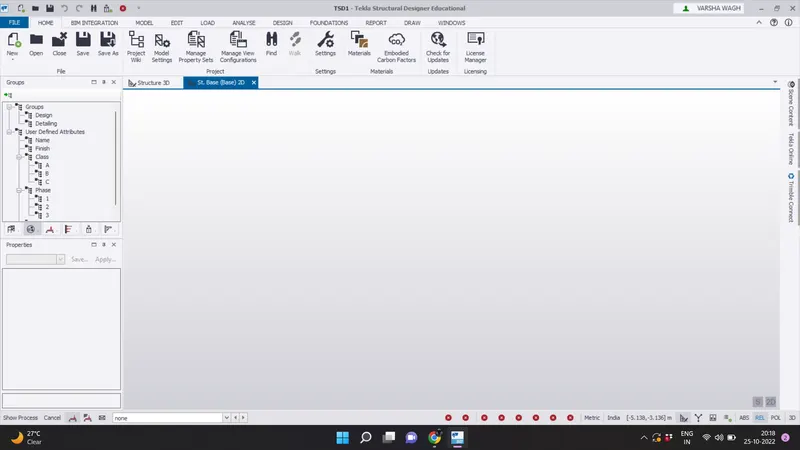
The project workspace is now active as shown and all the Ribbons and menu bars are visible now.
2.Scene Content
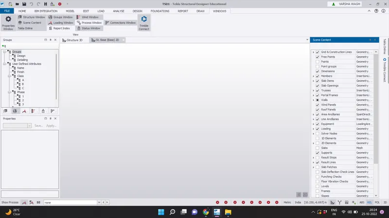
To access screen content menu, click on Windows tab and then click on Screen content option.
The screen content checkbox appears will open now and it consist of checkbox to select which all elements are to be made visible and hidden
3.Create two scene views
While creating a new Tekla file itself, the software automatically creates two default views like 2D and 3D.
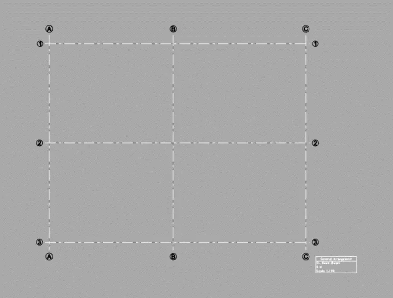
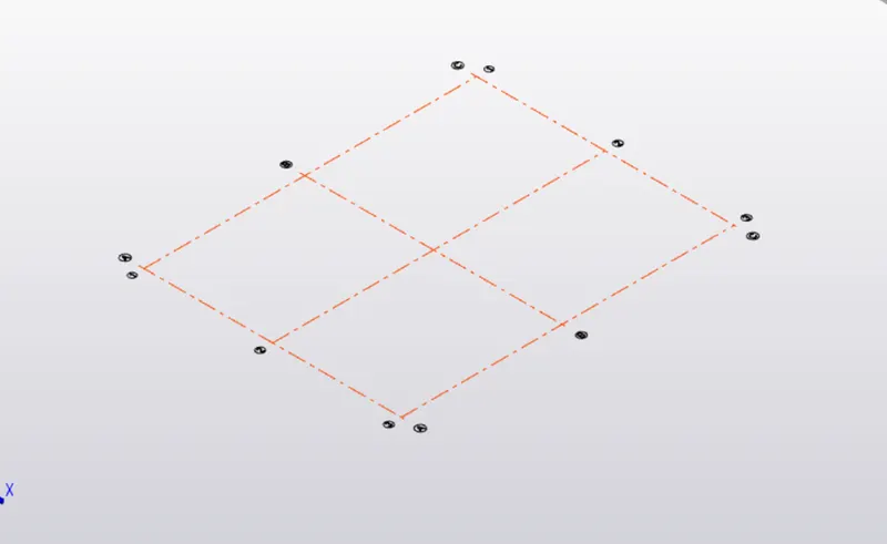
Grid lines was drawn to shown the different views
Two scene view -
- 2D view of grid line
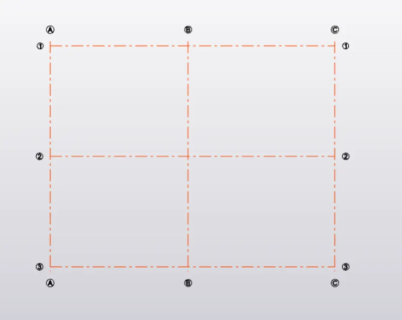
- Scene plan view
- 3D view
Loading drop list -
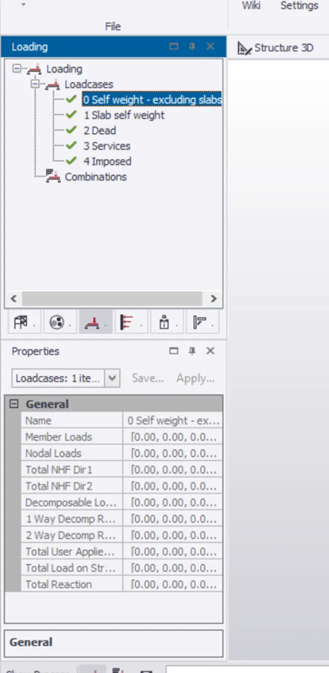
- Left side of workspace there is loading option and click on it we get loading drop list
- And below that there is loadcases box appear
Properties windows -
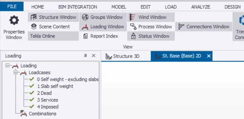
- Select window tab and in that select properties window
2)
Aim - To create a new file in TSD and set up the settings for a steel building to have member grade Fe410 and concrete grade of M30 as per IS codes and also provide covers too the members
Procedure -
- Open the Tekla structural designer software and click on new option to create new model
- Then select material option from home tab

- Click on material option and the material dialogue box appears and the select the option material
- Under material drop down the list and select material type as steel and grade as Fe 410
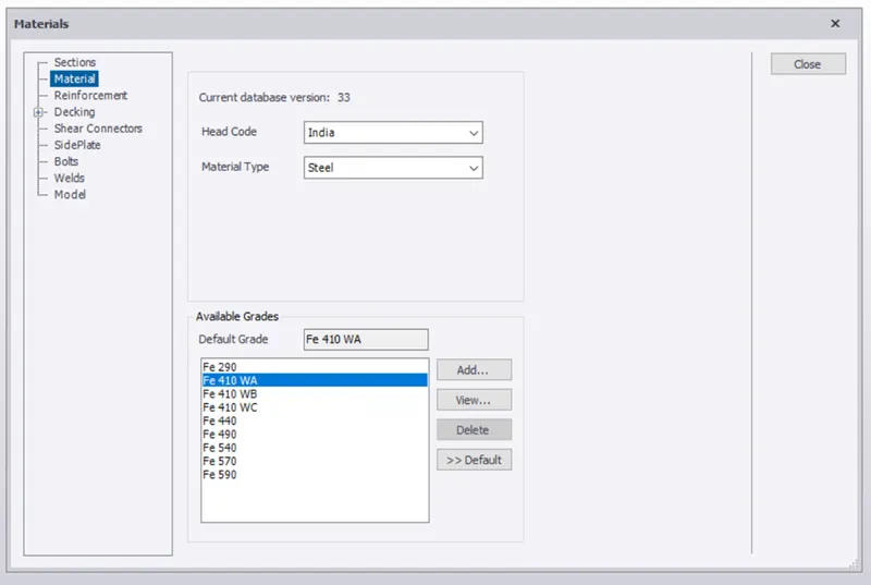
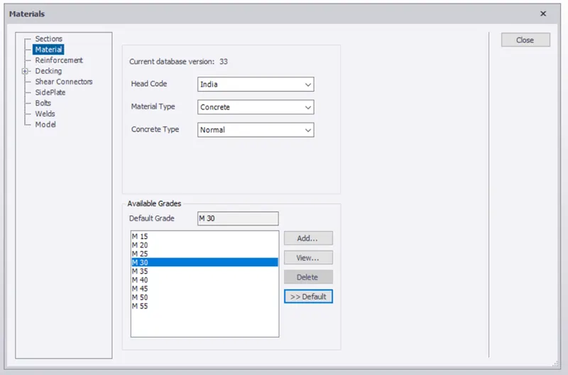
- Then select material type as concrete and also select grade as M30
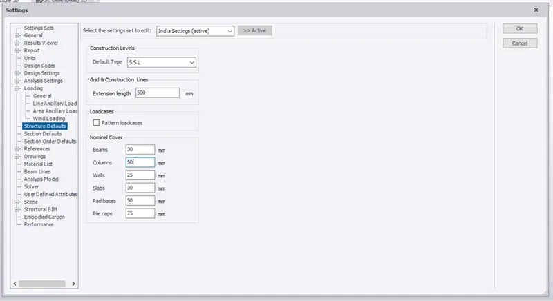
- To change the cover thickness,click on setting option and under the loading section select structure default
- Select SSL as default type and column cover as 50mm,slab as 30mm, and pile cap as 75mm
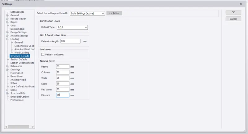
- Select TOF as default type and cover for column as 40mm,slab as 25mm and pile cap 75mm
3)
Aim - With the reference to the input drawing given,study the steel building plan and to summarize our understanding of the plan
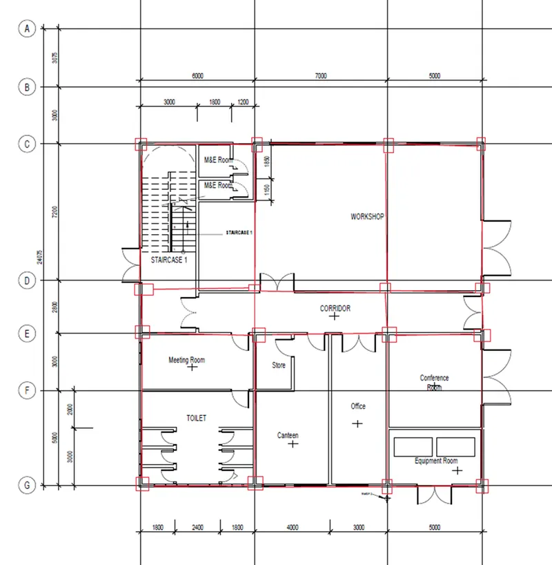
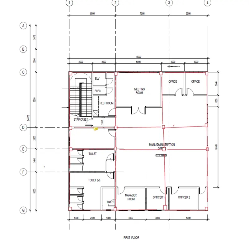
Column Position -
- Columns are placed at the corners of the builiding and intersection of beam
- Suppose the distance is larged,divide it into half and place the column at centre
- Column should not be placed at opening of door
- For placing of column avoid small space
Elevation -
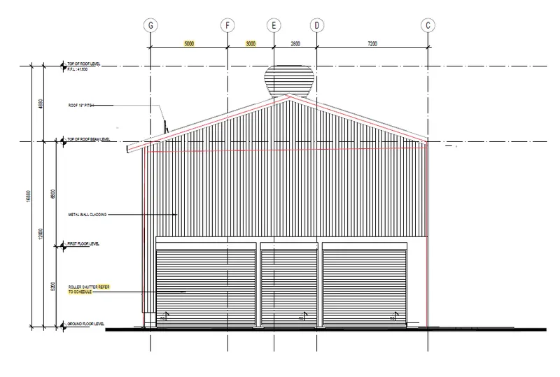
Ground floor -
First floor -
4)
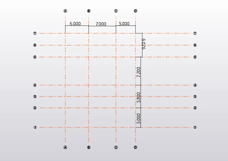
Aim - To model grid lines and construction levels as per given attachment
Procedure -
- Open the Tekla structural designer software and click on new option and new model workspace will appear
- In the model toolbar select construction levels and the construction level dialogue box is appear
- Name each levels like base,ground floor,1st floor and roof and also height is assigned
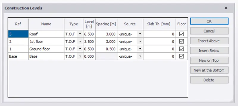
- Now,using grid line and quick parallel line option the vertical and horizontal grids are drawn as per requirement