To calculate the dead , live and wind load for RC residential structure and to apply them using TSD
- Calculate dead load in design report based on IS code and apply dead load on the model
- Finishes of 50mm
- Slab thickness as per the design
- Brick wall load
- Roofing load
AIM:- To calculate dead load in design report based on IS code and to apply dead load on the model
INTRODUCTION:- Dead load are normally the weight of th structural member which includes the weight of the slab, beam, column, roof, etc that are permanently available in the structure. Code refered for dead load is IS 875, part 1.
PROCEDURE:-
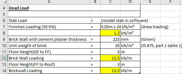
- Data for dead load is calculated and inputed in MS EXCEL as shown below.
- Dead load of the slab is automatically designed by software and applyied to the beam.
- Given, floor finishes = 50mm and brick wall thickness= 225 mm (as per plan)
- Consider unit weight of brick =20kN/m3
- Floor finish load = finish thickness x unit weight of concrete
= 0.05m x 24 kN/m3 = 1.2 kN/m2
- Brickwall loading for ground floor= unit weight of brick x floor height from ground floor to first floor x brickwall thickness
= 20 kN/m3 x 3m x 0.225 m
= 13.5 kN/m
- Similary, Brickwall loading for first floor= 13.5 kN/m
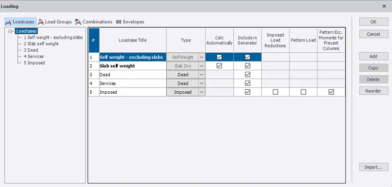
- Under load tab, select loadcases from ribbon window to check loadcase.
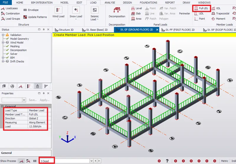
Ground Floor
- Select the Dead loadcase from the loading tab.
- In the first floor, select Full UDL from ribbon window to apply the brickwall load of 13.5kN/m.
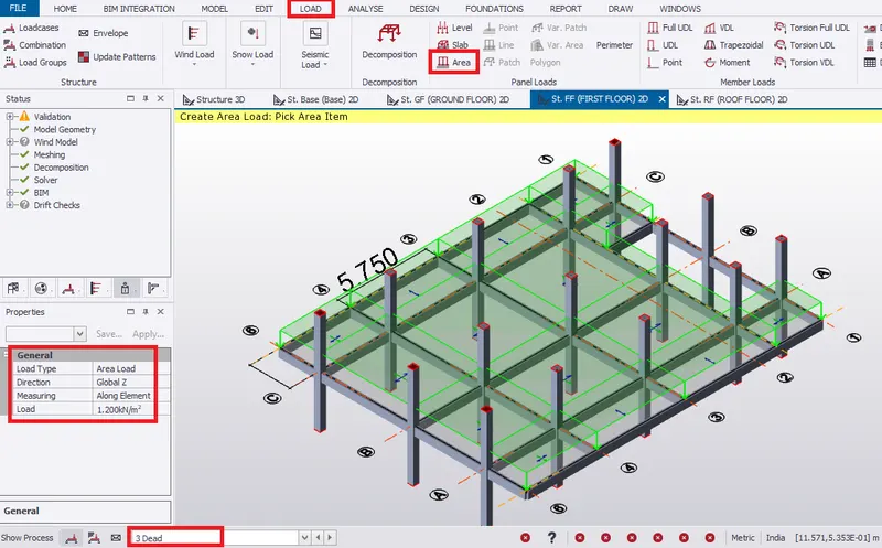
First Floor
- Select the Dead loadcase from the loading tab.
- In the first floor, select area load from ribbon window to provide floor finishes load on the slab.
- In property window, change load to 1.2 kN/m2 along global Z direction.
- Pick the area to create load area of 1.2 kN/m2.
- Apply brickwall load of 13.5 kN/m by selecting Full UDL from ribbon tab.
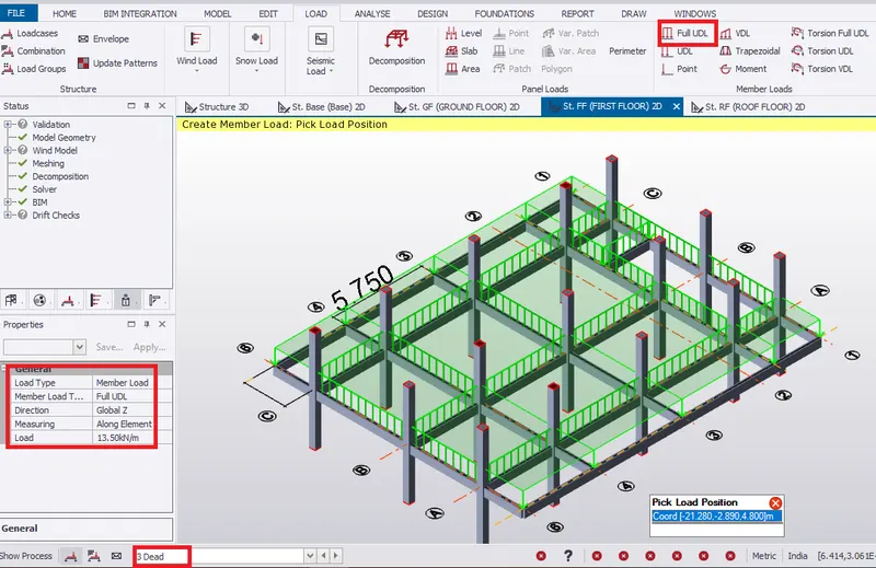
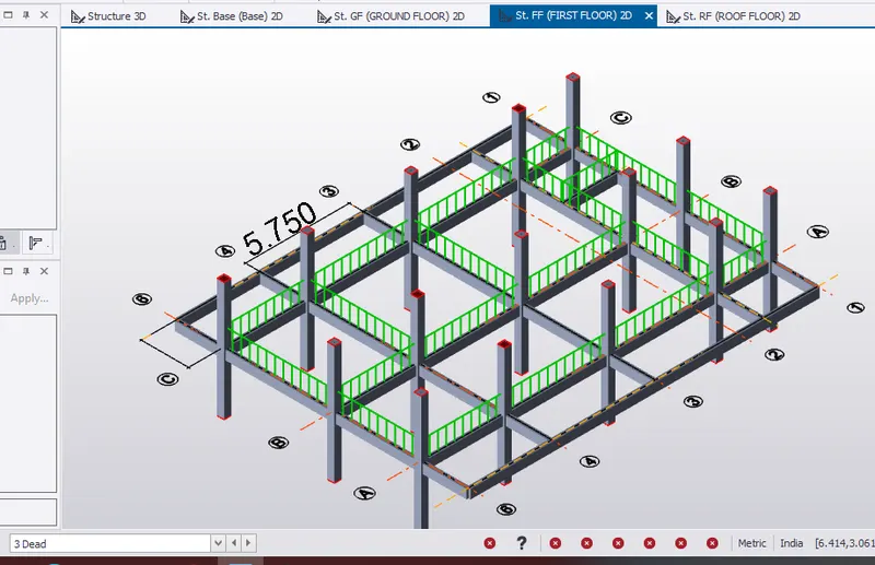
- Apply the brickwall load of 13.5kN/m away from the member(ie, on the slab).
- Select line load by picking the reference point, then specify the distance from grid line 6.
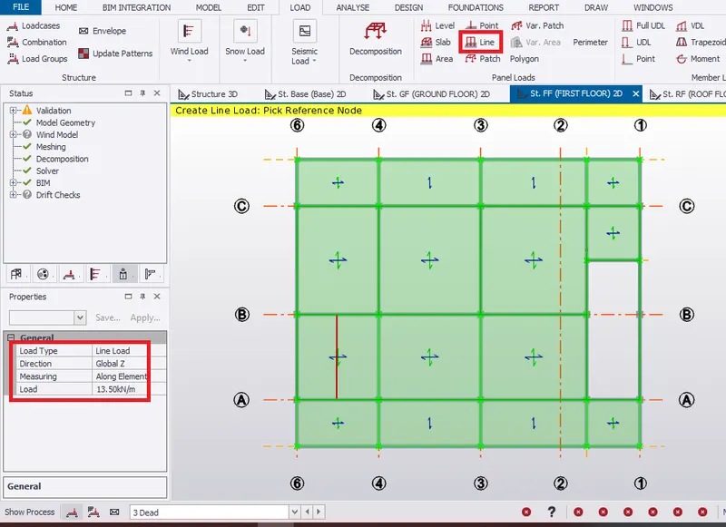
- Therefore, dead loads acting on first floor.
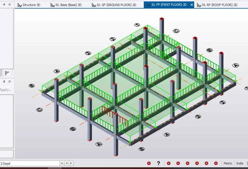
Roof Floor
- Select the Dead loadcase from the loading tab.
- In the first floor, select area load from ribbon window to provide floor finishes load on the slab.
- In property window, change load to 1.2 kN/m2 along global Z direction.
- Pick the area to create load area of 1.2 kN/m2.
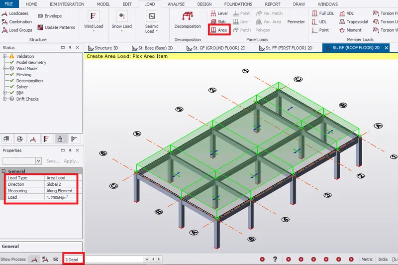
RESULT:- Hence, calculated dead load in design report based on IS code and applied dead load on the model.
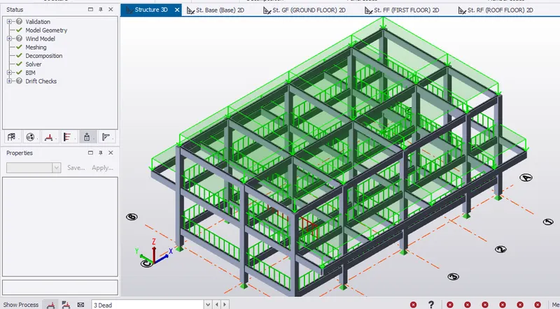
- Calculate live load in design report based on IS code and apply dead load on the model
AIM:- To calculate live load in design report based on IS code and apply dead load on the model
INTRODUCTION:- Live load are usually due to the weight of the occupant or weight of anything that is moving or varing. Code refered for live load is IS 875, part 2,1987, table 1 for industrial building.
PROCEDURE:-
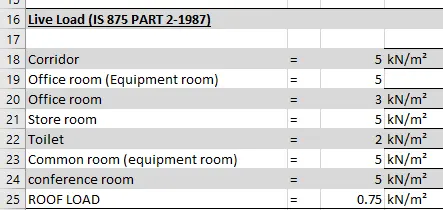
- Data for live load is inputed in MS EXCEL as shown below.
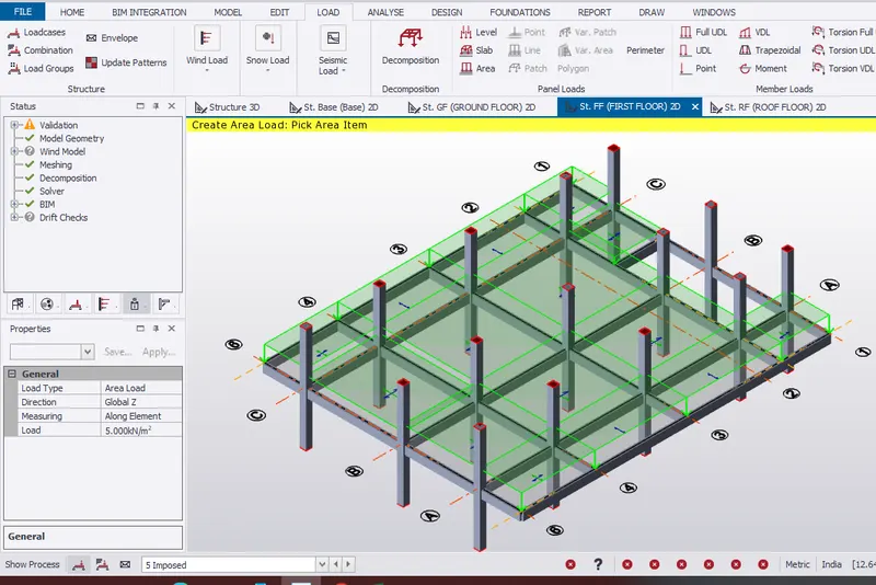
First Floor
- Select the Imposed loadcase from the loading tab.
- Select area load from ribbon window to provide live load on the slab.
- In property window, change load to 5 kN/m2 along global Z direction to apply load for corridor.
- Pick the area to create load area of 5 kN/m2.
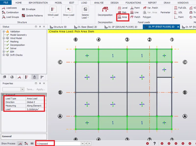
- Similarly, apply load to rest of the slab area based on the requirement as tabulated.
Roof Floor
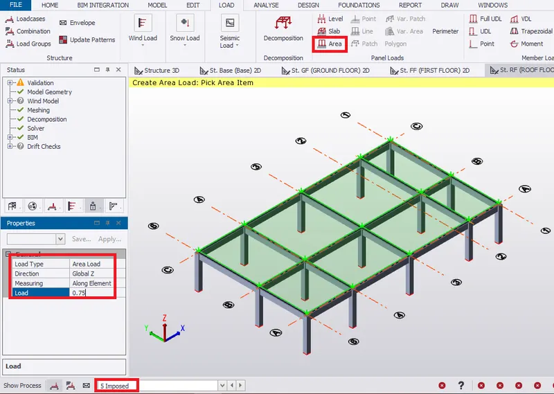
- Select the Imposed loadcase from the loading tab.
- Select area load from ribbon window to provide live load on the roof slab.
- In property window, change load to 0.75 kN/m2 along global Z direction to apply load for roof.
- Pick the area to create load area of 0.75 kN/m2.
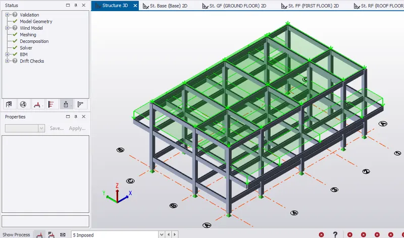
RESULT:- Hence, calculated live load in design report based on IS code and applied live load on the model.
3. Generate manual wind loading in the design report based IS code as per the following input
- Basic wind speed = 50m/s
- Terrain category 2
AIM:- To Generate manual wind loading in the design report based IS code as per the following input
- Basic wind speed = 50m/s
- Terrain category 2
INTRODUCTION:- Wind load is manually calculated based on the terrain category, basic wind speed and dimension of the structure both vertical and horizontal. Code refered for wind load is IS 875, part 3, 2015.
PROCEDURE:-
- Consider IS 875-3 (2015) for manuel wind load calculation for design report.
- Given, basic wind speed as 50m/s and terrain category as 2.
- Consider following data for calculation:-
- Life of the structure= 50 years (Table 1, Cl. 5.3.1)
- Class of structure = A (Cl. 5.3.2.2)
- Total length of the building, l= 19.675 m
- Total width of the building, w= 15.94 m
- Total height of the building, h= 8.1 m
- Therefore, l/w= 1.23 and h/w= 0.51.
Step 1
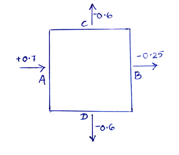
External pressure cofficient, Cpe
As per IS 875-3, Table 5
- Building height ratio= 1/2< h/w< 3/2
- Also, Building plan ratio= 1< l/w< 3/2
- Also, Building plan ratio= 1
Step 2
Find factors (k1, k2, k3, k4)
- From table 1 for wind speed of 50 m/s, k1= 1
- From table 2 with terrain category 2 and class of the building A
- Building height= 8.1m
- For 10m tall building, k2 value is 1.
- Therefore, 8.1 m tall building, k2= 1
- From Cl. 6.3.3, Topography Factor, k3= 1
- From Cl 6.3.4, Importance Factor, k4= 1.15 (for industrial building)
Step 3
To calculate Design Wind Speed (from Cl 6.3)
Vz= Vb x k1 x k2 x k3 xk4= 50x 1 x 1 x 1 x 1.15 , Vz= 57.5 m/s
Step 4
Design wind Pressure (from Cl 7.2)
Pz = 0.6 x Vz^2 =0.6 x 57.5^2 = 1983.75 N/m^2
Pz =1.99 kN/m^2
Step 5
Wind direction (upto roof level)
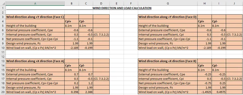
RESULT:- Hence, generated manual wind loading in the design report based on IS 875 part 3 code.
4. Based on the above calculation apply the loadings on the model
AIM:- To apply wind load on the model based on the above calculation.
INTRODUCTION:- Wind load acts both internally and externally on the structure based on the wind direction and height of the structure.
PROCEDURE:-
- To create wind load, select loadcase from load tab.
- Add loadcases Wind+Y+Cpi, Wind+Y-Cpi, Wind+X+Cpi and Wind+X-Cpi.
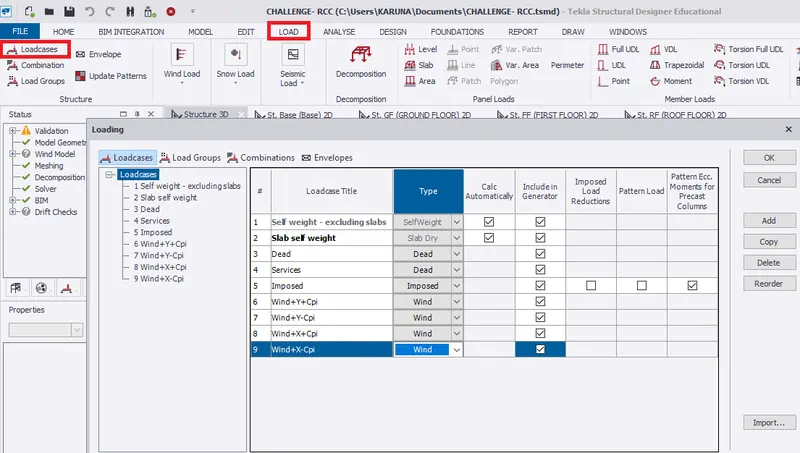
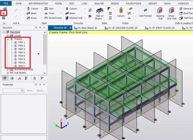
- Firstly, select frame ribbon from model tab.
- Pick the grid line to create frames to create wind panels. Therefore, frames are created as shown in projecct window.
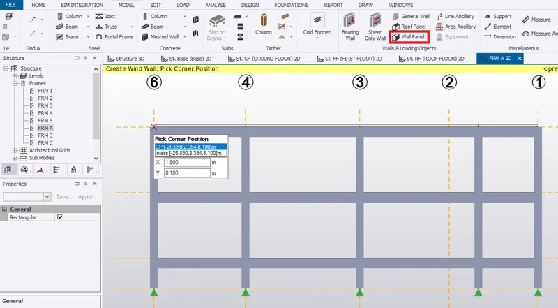
- Select frame A from project window to create wall panel for the structure.
- Select wall panel from ribbon tab.
- Pick the corners positions of the frames to create wind wall as shown below.
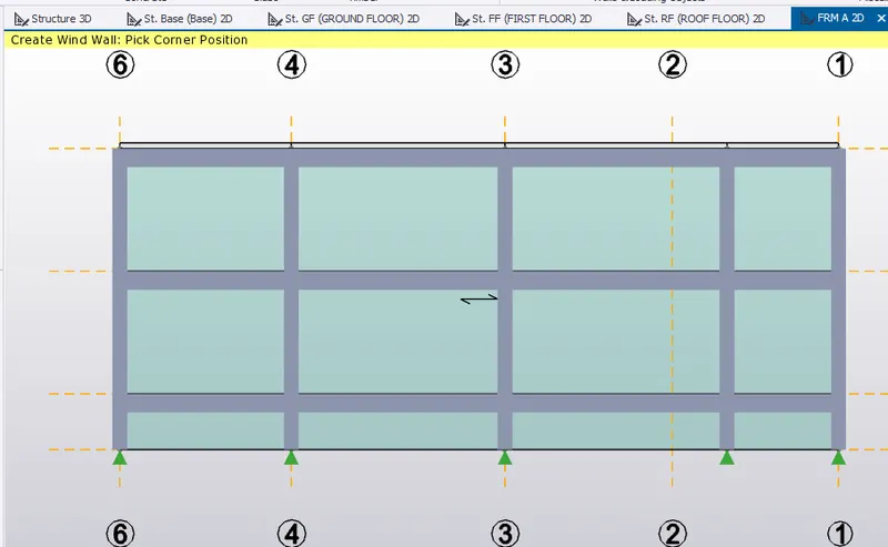
- Similarly, create wind wall panel for frame C, 1 and 6.
Wind+Y+Cpi
- Select frame C, select Wind+Y+Cpi from the loading window.
- Select the area load, change load intensity to 2.2 kN/m2 and change direction to Y.
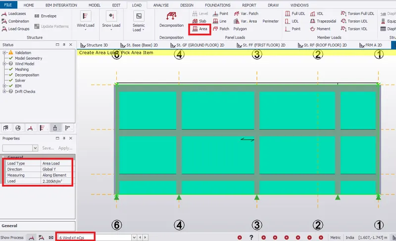
- Similary, select frame A, select Wind+Y+Cpi from the loading window.
- Select the area load, change load intensity to 2.2 kN/m2 and change direction to Y
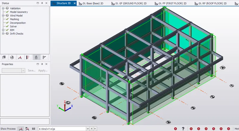
- Next to apply internal pressure, select frame 1, select Wind+Y+Cpi from the loading window.
- Select the area load, change load intensity to 1.5 kN/m2 and change direction to X
- Similarly, select frame 6, select Wind+Y+Cpi from the loading window.
- Select the area load, change load intensity to -0.4 kN/m2 and change direction to X.
- Check in structural 3D view.
Wind+Y-Cpi
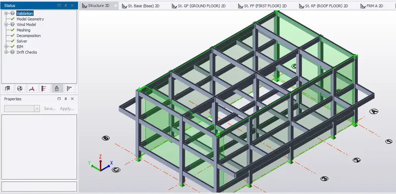
- Select frame C, select Wind+Y-Cpi from the loading window.
- Select the area load, change load intensity to 0.2 kN/m2 and change direction to Y.
- Similary, select frame A, select Wind+Y-Cpi from the loading window.
- Select the area load, change load intensity to 0.2 kN/m2 and change direction to Y
- Next to apply internal pressure, select frame 1, select Wind+Y-Cpi from the loading window.
- Select the area load, change load intensity to 0.5 kN/m2 and change direction to X
- Similarly, select frame 6, select Wind+Y-Cpi from the loading window.
- Select the area load, change load intensity to -2.4 kN/m2 and change direction to X.
- Check in structural 3D view.
Wind+X+Cpi
- Select frame C, select Wind+X+Cpi from the loading window.
- Select the area load, change load intensity to 2.2 kN/m2 and change direction to Y.
- Similary, select frame A, select Wind+X+Cpi from the loading window.
- Select the area load, change load intensity to -2.2 kN/m2 and change direction to Y
- Next to apply internal pressure, select frame 1, select Wind+X+Cpi from the loading window.
- Select the area load, change load intensity to -1.5 kN/m2 and change direction to X
- Similarly, select frame 6, select Wind+X+Cpi from the loading window.
- Select the area load, change load intensity to 0.4 kN/m2 and change direction to X.
- Check in structural 3D view.
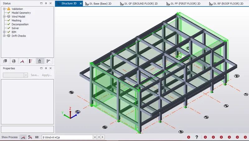
Wind+X-Cpi
- Select frame C, select Wind+X-Cpi from the loading window.
- Select the area load, change load intensity to 0.2 kN/m2 and change direction to Y.
- Similary, select frame A, select Wind+X-Cpi from the loading window.
- Select the area load, change load intensity to -0.2 kN/m2 and change direction to Y
- Next to apply internal pressure, select frame 1, select Wind+X-Cpi from the loading window.
- Select the area load, change load intensity to 0.5 kN/m2 and change direction to X
- Similarly, select frame 6, select Wind+X-Cpi from the loading window.
- Select the area load, change load intensity to 2.4 kN/m2 and change direction to X.
- Check in structural 3D view.
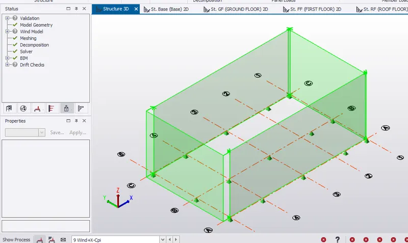
RESULT:- Hence, applied the wind load on the model based on the above wind load calculation.