To Generate report for Steel Industrial and RC structures using TSD
- Generate report for the steel building design from challenges 1 – 6 along with the loading summary
AIM:- To generate report for the steel building design from challenges 1 – 6 along with the loading summary
INTRODUCTION:- Report generation helps us to get detailed report for each members and completed details of loadcases, its combinations, analysis and design calculation details of each member of a steel structure.
PROCEDURE:-
- Before report generation, analysis the model.
- Under Report tab, select Beam End forces and model Report to create content for report.
- To create report, drag selected chapters under structures which includes levels, loadings, loadcase summary, combinations and seismic loading system. Click OK.
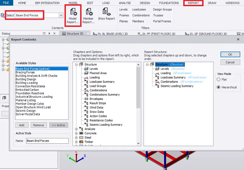
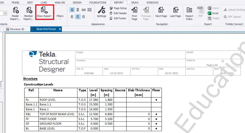
- Select Show report to generate the report.
- Therefore, report is generated which shows the construction level.
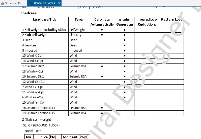
- Under levels, loadcases are shown.
- Followed by nodal and member loads on each floor.
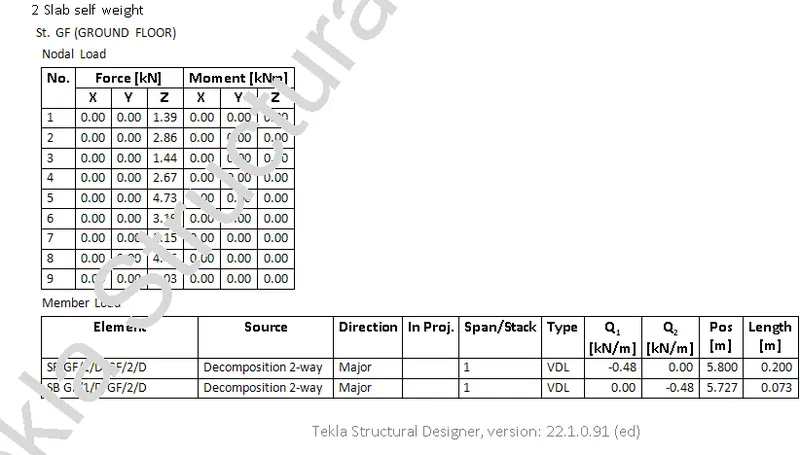
- Go to Next page to see rest of the member load in the ground floor.
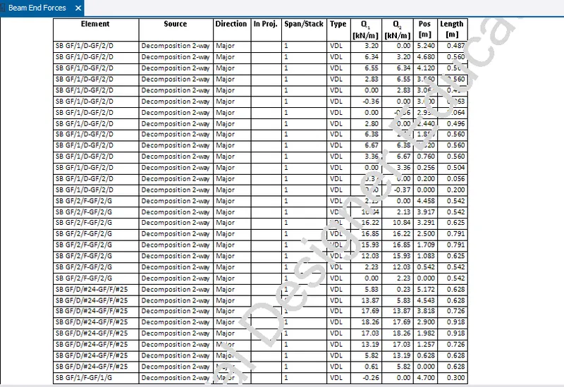
- Page 5 starts with member load in first floor.
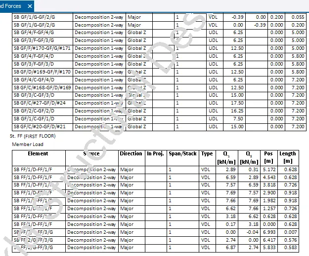
- Similarly, this continue with top of beam level.
- Page 14 starts with loads acting on ground floor which includes Dead load (Nodal load, Area load, Line load and member load)
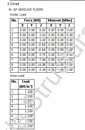
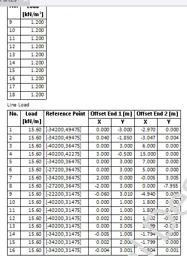
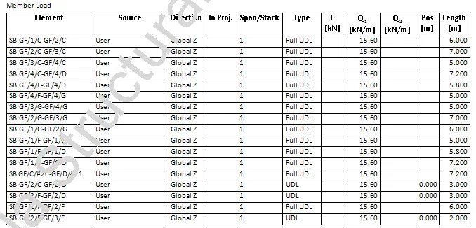
- Similarly, this continue with 1st floor and top of roof beam level which includes Dead load (Nodal load, Area load, Line load and member load)
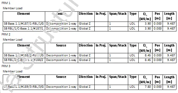
- Member load with dead load for each frame is shown.
- Imposed load which includes Nodal load, Area load, Member load from ground floor to top of roof beam level
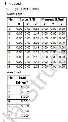
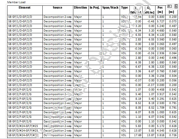 IMPOSED LOAD ON GROUND FLOOR
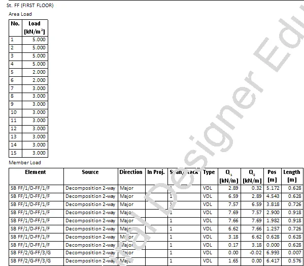 IMPOSED LOAD ON FIRST FLOOR
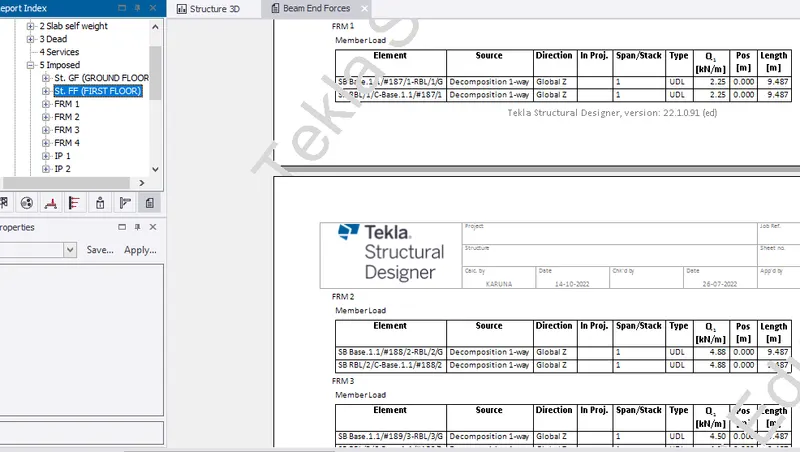 IMPOSED LOAD ON EACH FRAMES
- Wind load on frame 1 with area and member load is included in report.
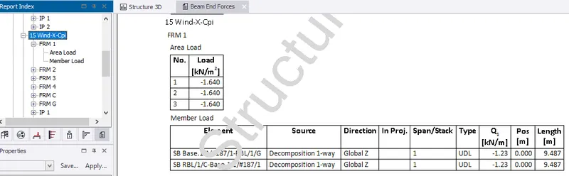
- Similarly, wind load(Wind-X-Cpi) on each frames with area and member load is included in report.
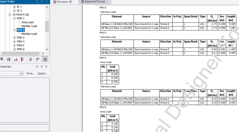
- Similarly, wind loads on each frames with area and member load is included in report.
- Next, load case summary (ie, slab self weight, dead load, imposed load, windload) are shown below.
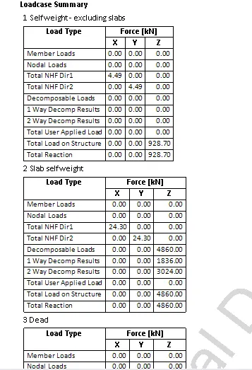
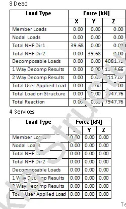
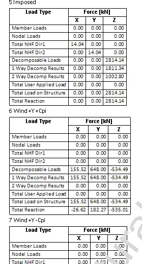
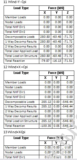
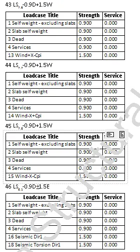
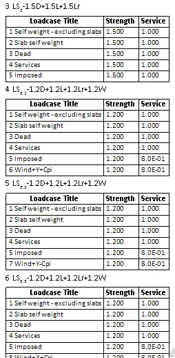
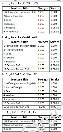
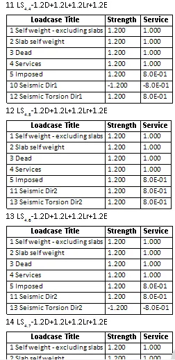
- Towards the end comes load combinations and its intensity.
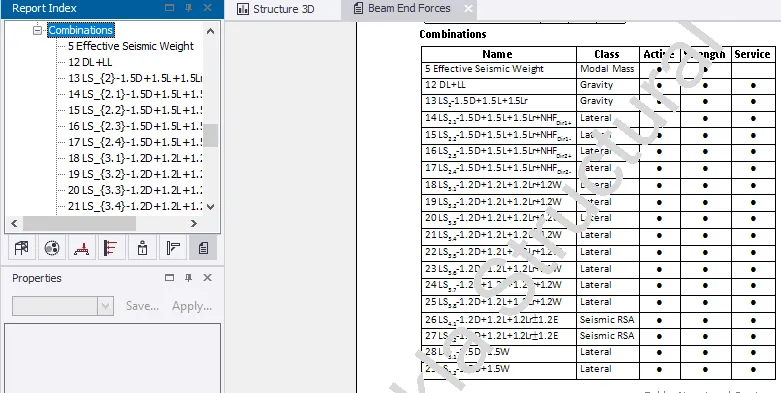
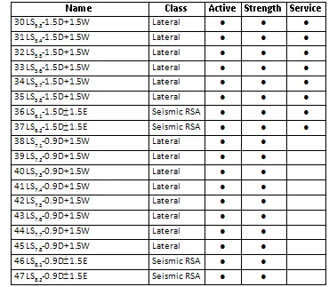
- Factor of safety for different load combination is shown.
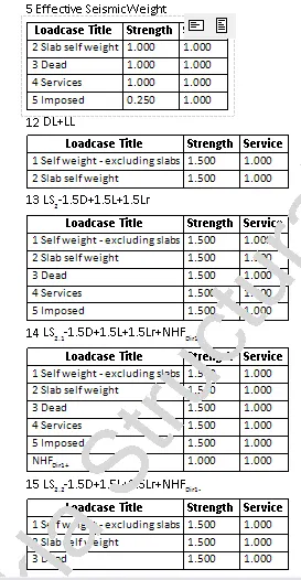
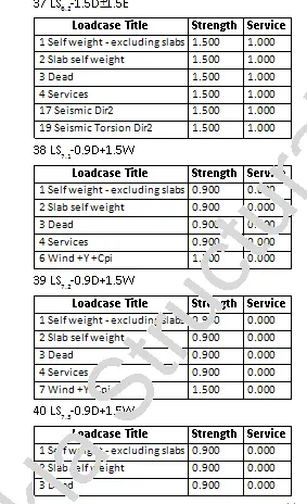
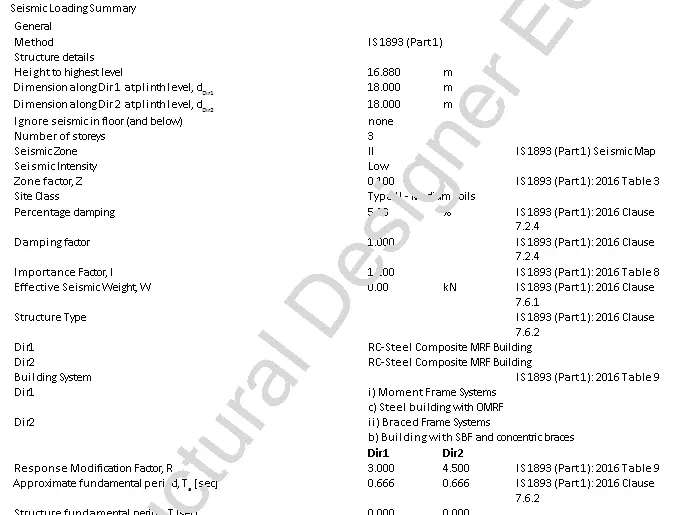
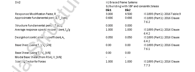
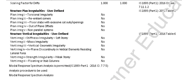
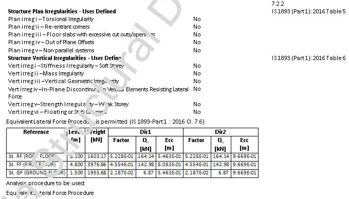
- Next, shows the seismic loading summary with codal provision.
Report generation for a particular member
Select a column
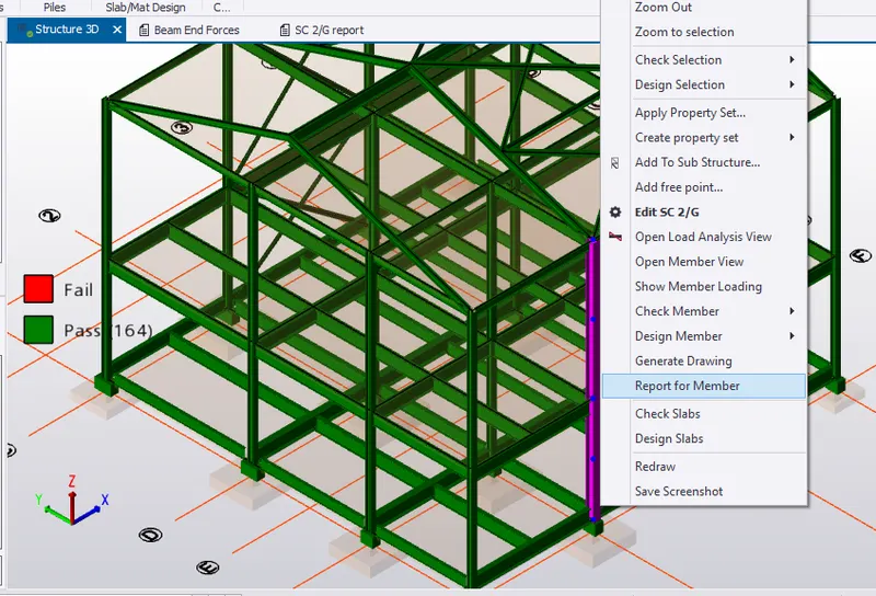
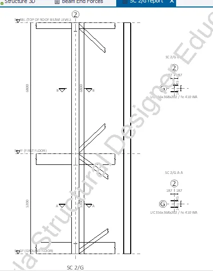
- Report for the particular column is generated with cross section
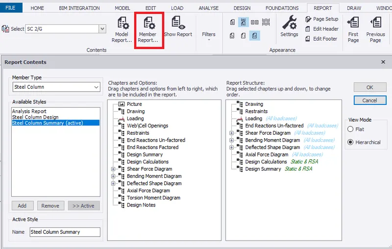
- Select Member report to include loading, shear force, bending moment, deflection and axial force diagram along with design calculation and summary.
- Report for loading.
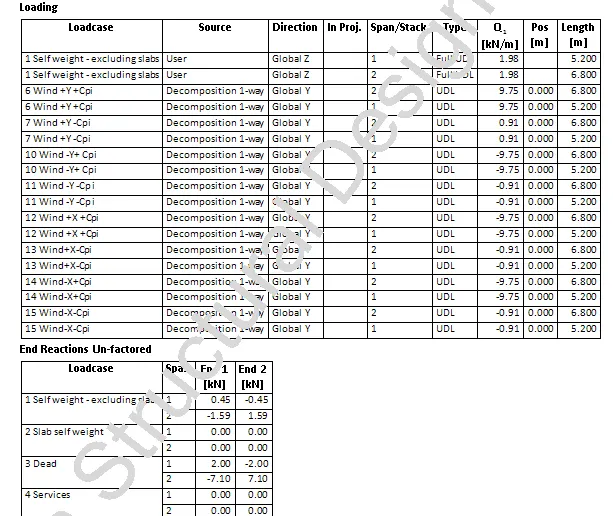
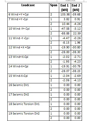
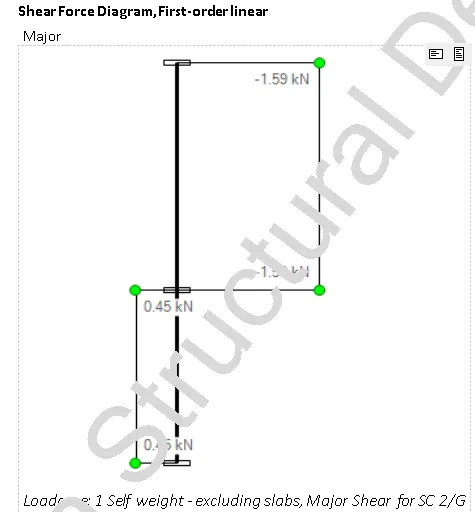
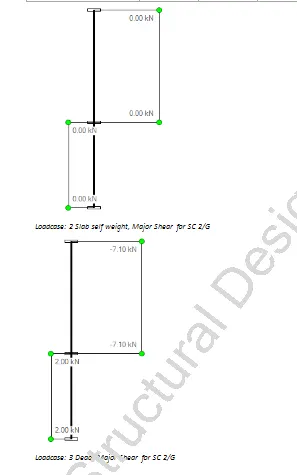
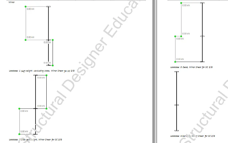
- Shear force diagram for both major and minor at different loadcases.
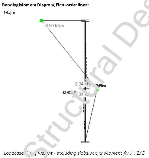
- Bending moment diagram for both major and minor at different loadcases.
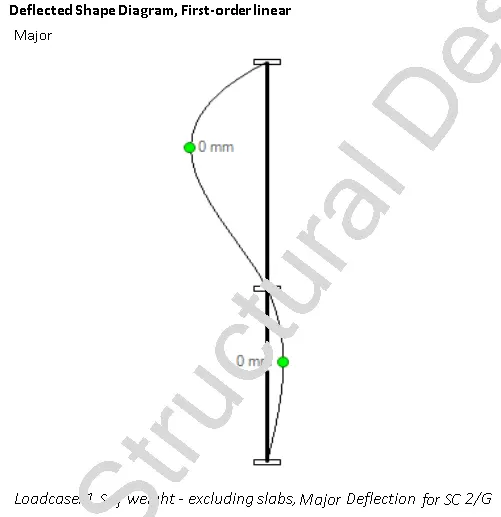
- Deflection diagram for both major and minor at different loadcases.
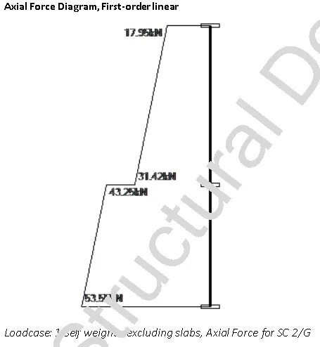
- Axial force diagram for both major and minor at different loadcases.
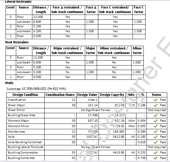
- Design Calculation is shown below .
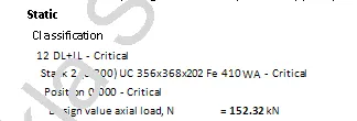
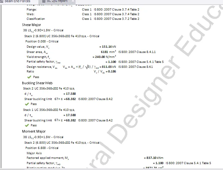
- Finally, design summary for column section is shown (as shown above).
Steel beam
- Select a steel beam
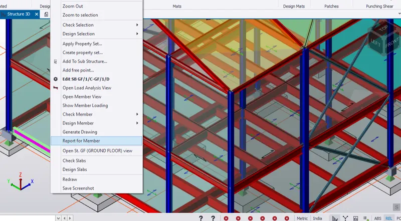
- Report details are generted with drawing and design summary.
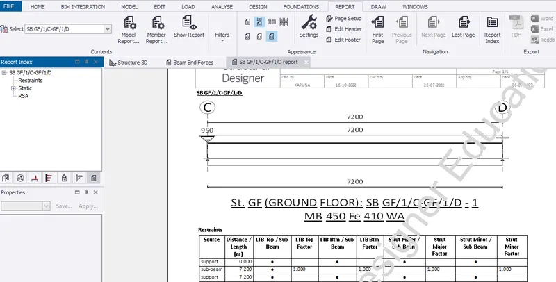
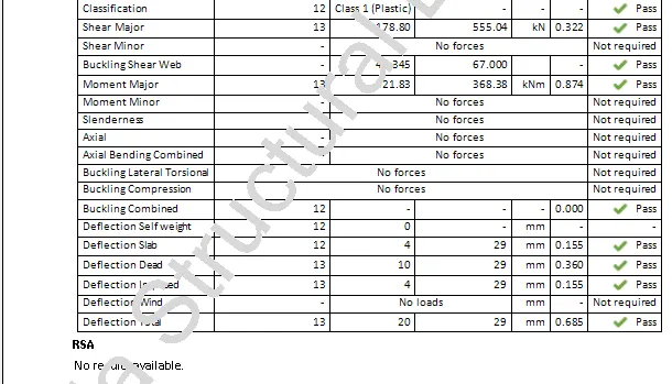 DESIGN SUMMARY
RESULT:- Hence, generated report for the steel building design from challenges 1 – 6 along with the loading summary
2. Generate report for RC structure along with the loading summary
AIM:- To generate report for the RC structure along with the loading summary
INTRODUCTION:- Report generation helps us to get detailed report for each members and completed details of loadcases, its combinations, analysis and design calculation details of each member of a RC structure.
PROCEDURE:-
1. Member Report
- Before report generation, analysis the model.
- Select roof floor from project window.
Concrete Beam Report
- To generate report for RC beam, select Report for Member.
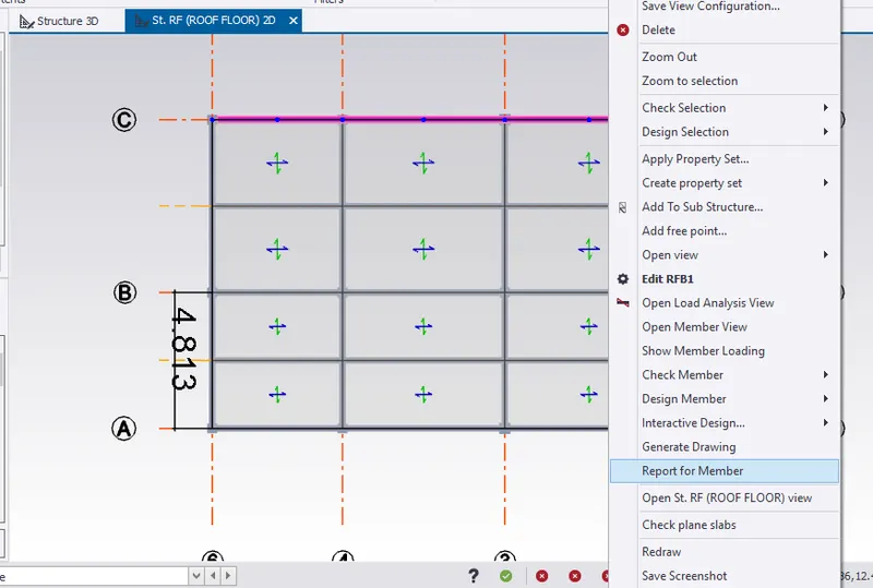
- Therefore, report for the beam is generated.
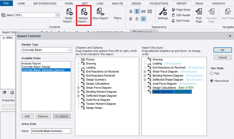
- Select Member report to edit the contents of the beam report.
- To create report, drag selected chapters under structures which includes drawings, loadings, shear force, bending moment, deflection and axial force diagram along with design calculation and summary. Click OK.
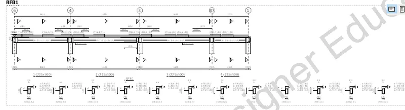
- Roof beam (RFB1) drawing is shown below.
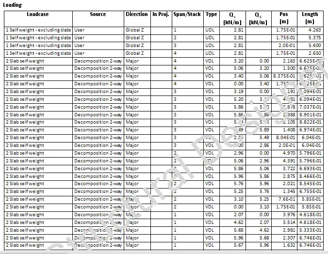
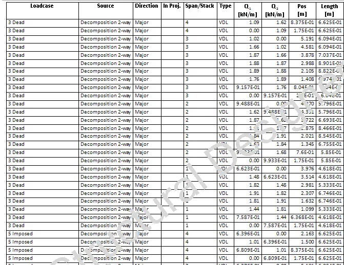
- Loadcase of the beam is noted.
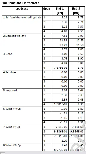
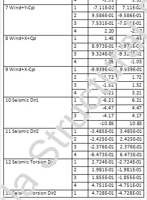
- Unfactored end reaction for each loadcase at each spans are shown.
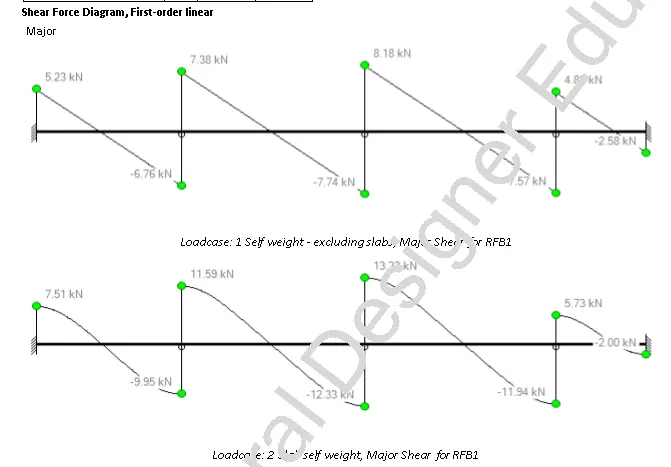
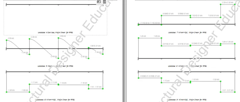
- Shear force diagram in 1st order linear for different loadcases is shown.
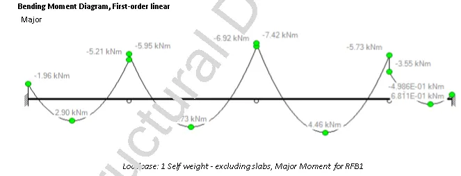
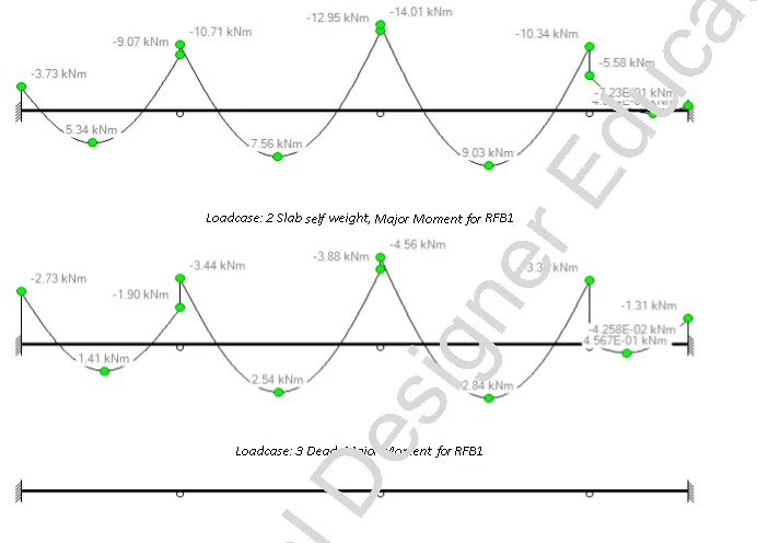
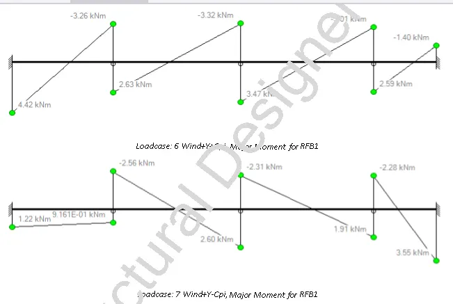
- Bending moment diagram in 1st order linear for different loadcases is generated.
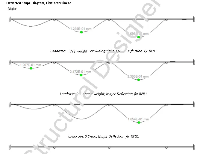
- Deflection diagram in 1st order linear for different loadcases is generated.
- Design calculation for roof beam (RFB1) is generated.
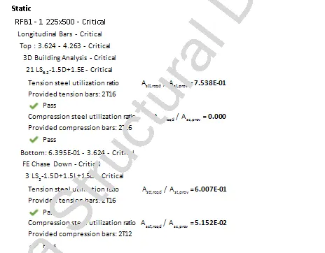 LONGITUDINAL BAR CALCULATIONS FOR RFB1-1
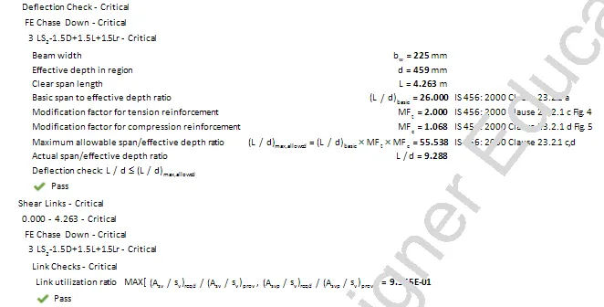 DEFLECTION AND SHEAR CALCULATIONS FOR RFB1-1
- Similarly, Design calculation for roof beam (RFB2, RFB3, RFB4) is generated.
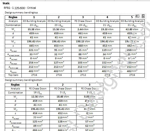
- Design summary of RFB1 is generated.
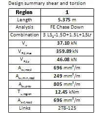
- Similarly, Design summary of RFB2, RFB3 , RFB4 is generated.
Concrete Column Report
- To generate report for RC column C11, select Report for Member.
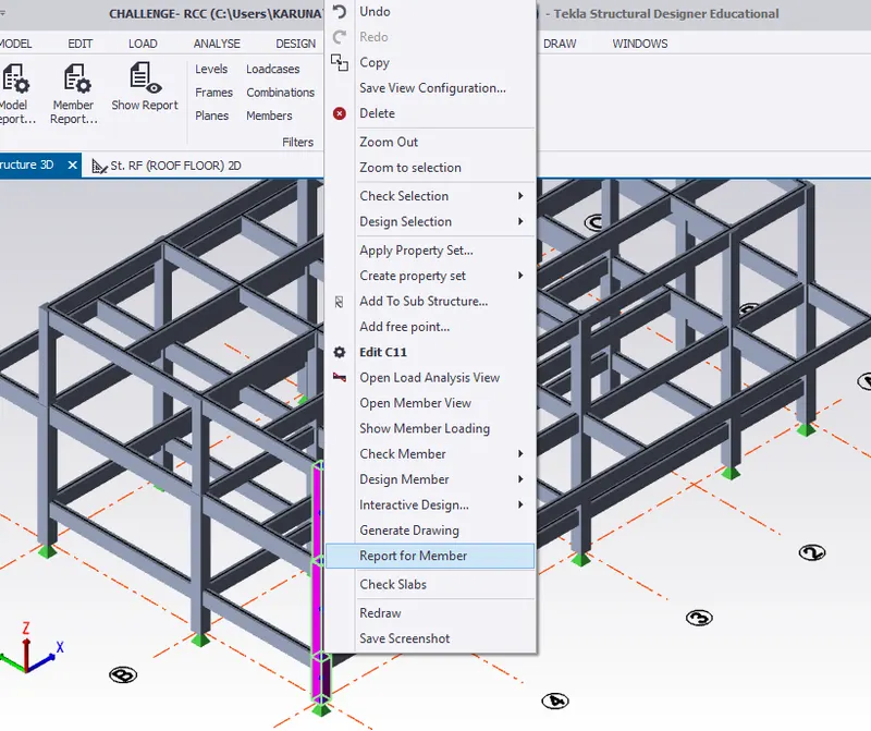
- Therefore, report for the column is generated.
- Select Member report to edit the contents of the column report.
- To create report, drag selected chapters under structures which includes drawings, loadings, shear force, bending moment, deflection and axial force diagram along with design calculation and summary. Click OK.
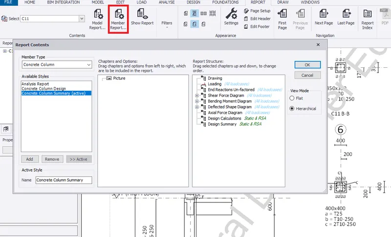
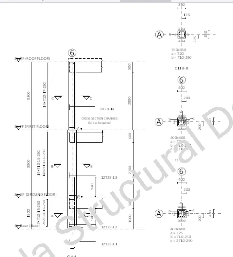
- Column(C11) drawing is generated.
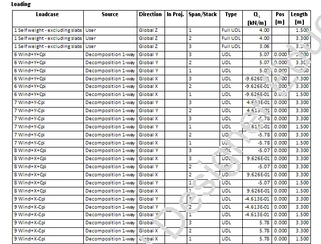
- Loadcase of the column is noted.
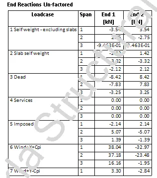
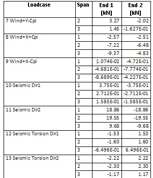
- Unfactored end reaction for each loadcase at each stack levels are shown.
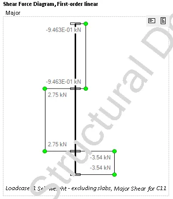
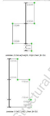
- Shear force diagram in 1st order linear for different loadcases is shown.
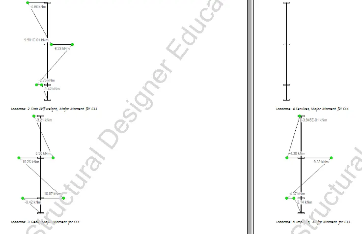
- Bending moment diagram in 1st order linear for different loadcases is generated.
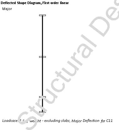
- Deflection diagram in 1st order linear for different loadcases is zero.
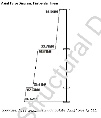
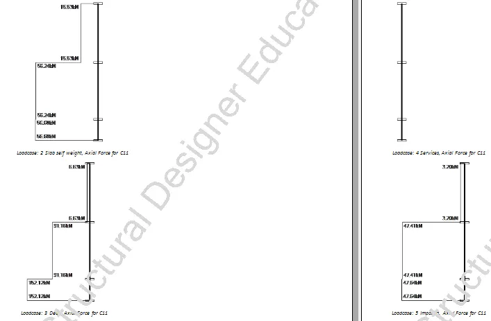
- Axial force diagram in 1st order linear for different loadcases is generated.
- Design calculation for rcolumn (C11) is generated.
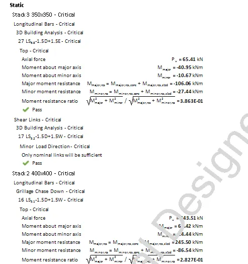 LONGITUDINAL AND SHEAR LINK BAR CALCULATIONS FOR STACK 3
- Similarly, Design calculation for stack 2 and 1 is generated.
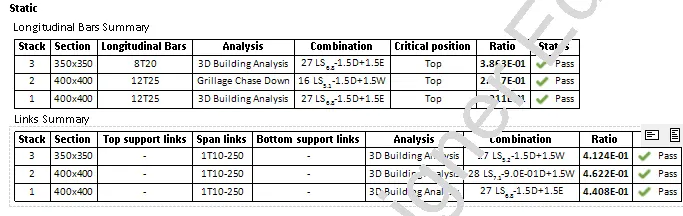
- Design summary of column is generated.
Concrete Slab Report
- Go to roof floor, To generate report for RC slab, select Report for Member.
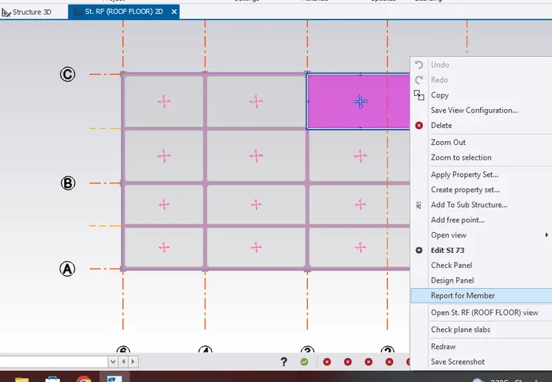
- Therefore, report for the slab is generated.
- Select Member report to edit the contents of the slab report.
- To create report, drag selected chapters under structures which includes design calculation and summary. Click OK.
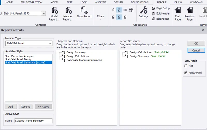
- Design calculation for slab S8, Panel SL73 is generated.
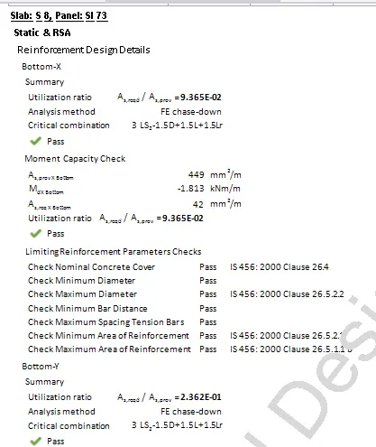
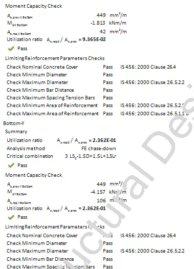 BOTTOM REINFORCEMENT DESIGN DETAILS
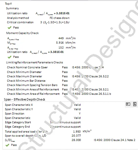 TOP REINFORCEMENT AND SPAN- EFEECTIVE DEPTH DESIGN DETAILS
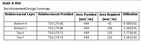
- Design summary reinforcement details are generated.
Foundation Report
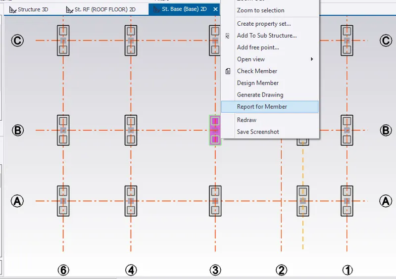
- Go to base floor, To generate report for RC pile cap, select Report for Member.
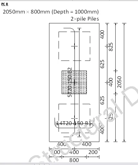
- Drawing of pile cap PC 8 is generated
- Design summary details with applied load, foundation details, shear check and punching shear are generated.
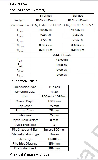
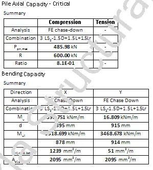
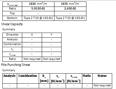
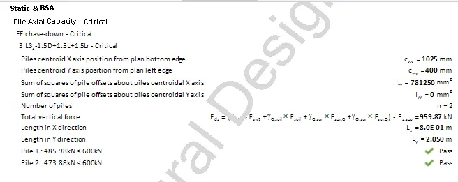
- Design calculation for pile cap are generated.
2. Model Report
- Under Report tab, select Beam End forces and model Report to create content for report.
- To create report, drag selected chapters under structures which includes levels, loadings, loadcase summary, combinations and seismic loading system. Click OK.
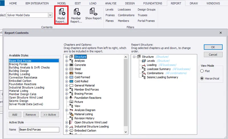
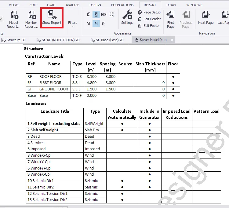
- Select Show report to generate the report.
- Therefore, report is generated which shows the construction level and loadcases.
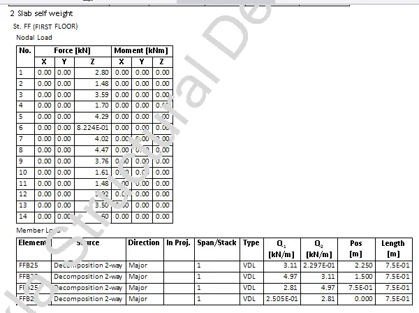
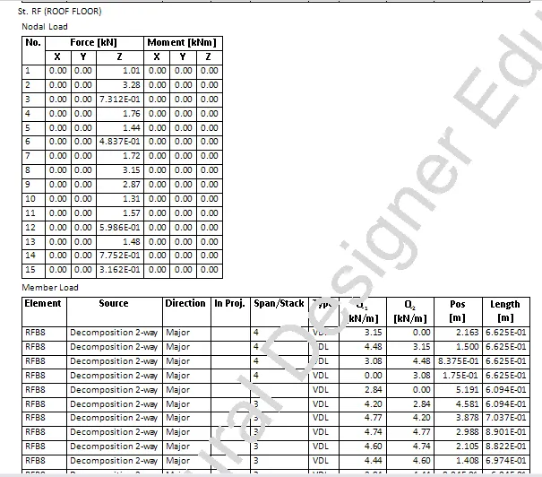
- Slab self weight (Nodal and member loads) on each floor.
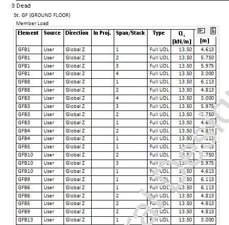
- Dead load of the ground floor with member load
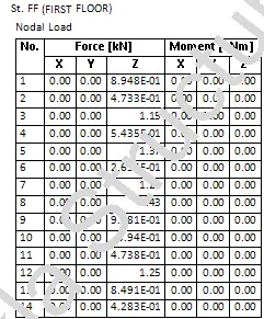
- Dead load of the first floor with nodal load, area load, member load
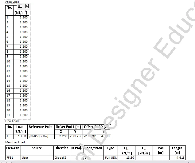
- Similarly, this continue with dead load on roof floor
- Imposed load on the first floor and roof floor which includes Nodal load, Area load, Member load from ground floor to top of roof beam level
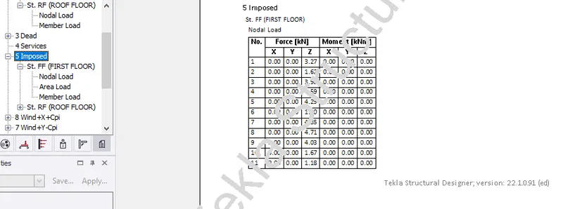
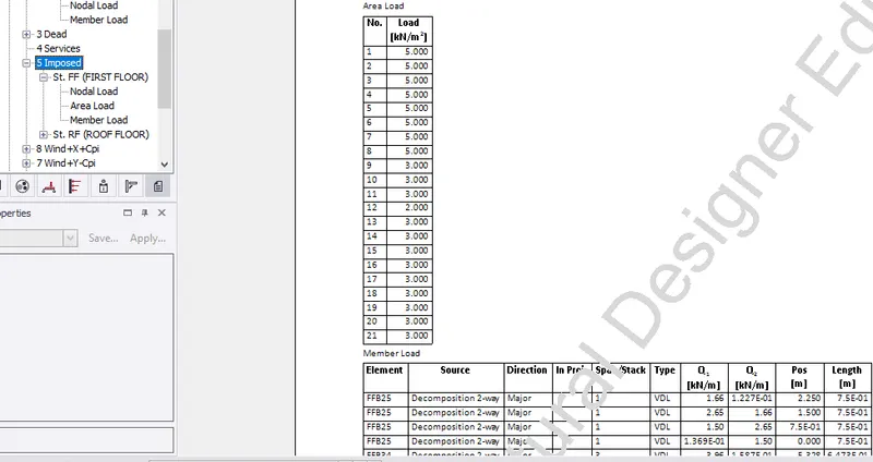 IMPOSED LOAD ON FIRST FLOOR
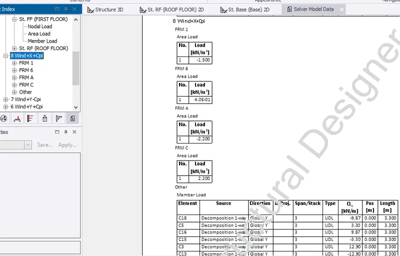
- Wind load, Wind+X+Cpi on each frames with area and member load is included in report.
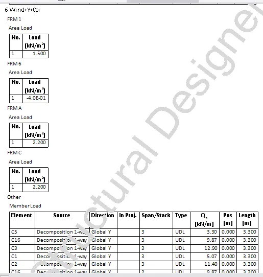
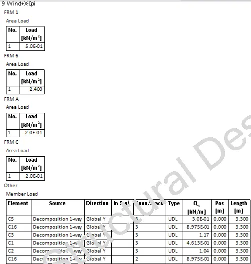
- Similarly, wind loads(Wind+Y-Cpi, Wind+Y+Cpi, Wind+X-Cpi) on each frames with area and member load is included in report.
- Next, load case summary for slab self weight, dead load, imposed load, windload and seismic load) are generated.
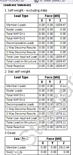
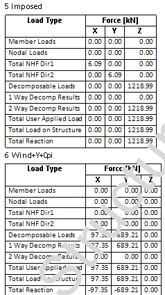 DEAD LOAD AND IMPOSED LOAD
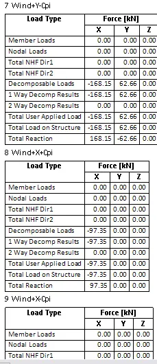
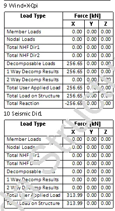
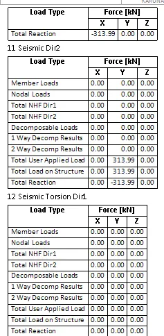 WIND AND SEISMIC LOAD
- Towards the end load combinations are generated
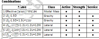
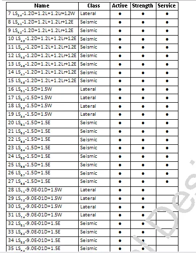
- Factor of safety for different load combination is shown.
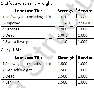
- The seismic loading summary with codal provision are generated.

- Select Building Analysis and Wind Checks from style
- Select Element member, Wind drift.
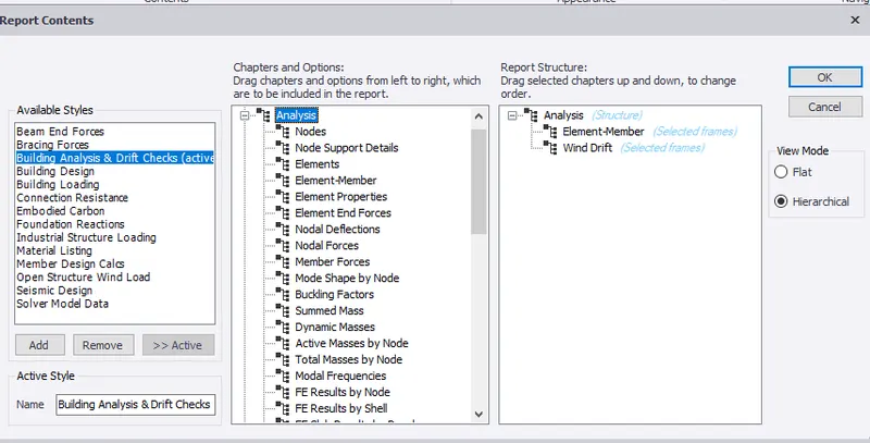
- Edit element member
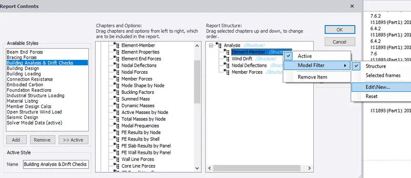
- Select frames 1, 6 and A.
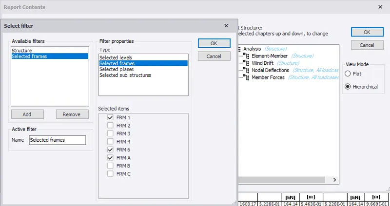
- Similarly, edit Wind drift by selecting the frames 1,6 and A. Click ok.
- Select Building Analysis and Wind Checks from ribbon tab. Select Show member to generate report.
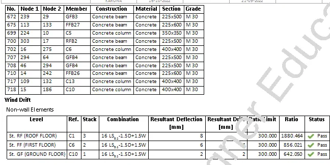
- Report for element member analysis is generated.
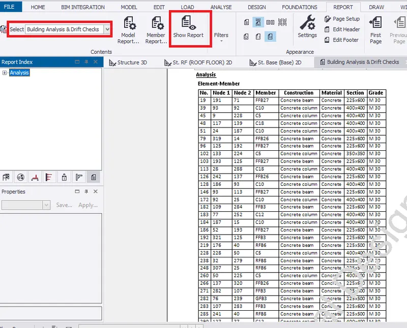

- Also, wind drift report is generated.
RESULT:- Hence, report for RC structure along with the loading summary is generated.
3. Update the layers settings in the model and generate plan drawings and details from the mode
AIM:- To Update the layers settings in the model and generate plan drawings and details from the mode
INTRODUCTION:- Drawing settings helps in setting layers configuration and style of drawing to genarated in 2D.
PROCEDURE:-
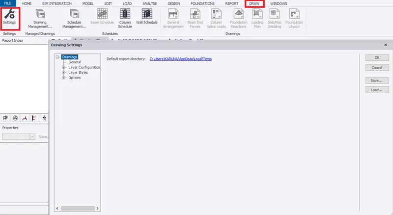
- Go to draw in tab window.
- Select drawing settings to set layers for the model so as to generate plan drawing
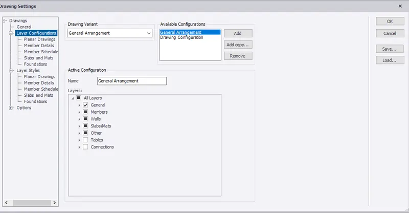
- Select layer configuration to modify the drawing category.
- Select member schedule to set layer configuration forbeams and columns.
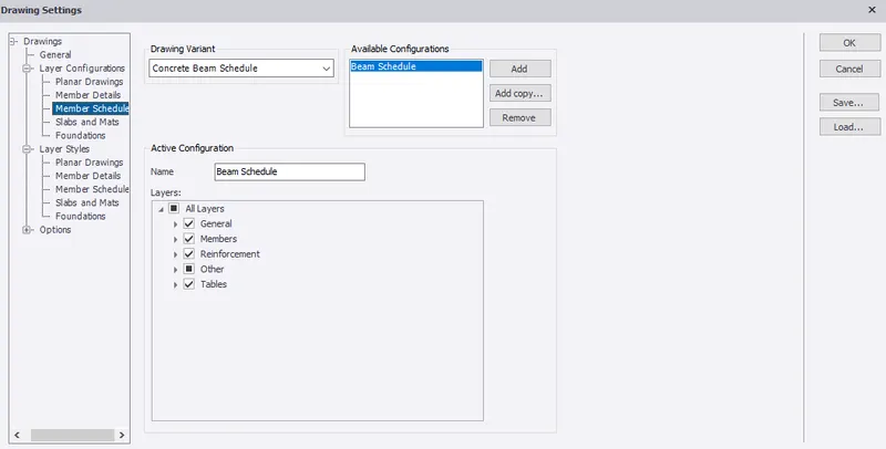
- In this settings layer styles can be modified in drawing variant.
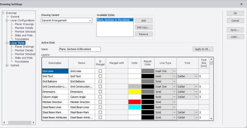
- Select Planar drawing from layar styles to change colour. Click ok.
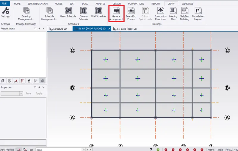
- Go to roof floor level in scene view.
- Select general arrangement from ribbon tab to create and save drawings in 2D view.
RESULT:- Hence, Updated the layers settings in the model and showed how to generate plan drawings and details from the model