Roof challenge
ROOF DESIGN
Objectives:
- To Design and Develop an Automobile Roof Assembly with the Front Roof Rail, Rear Roof Rail, Centre Roof Reinforcements and Bow Roofs.
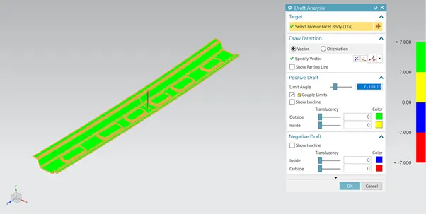
- To perform the Roof Curvature study and Draft Analysis
- To perform the Section Inertia Analysis
Introduction: An automobile roof or car top is the portion of an automobile that sits above the passenger compartment, protecting the vehicle occupants from sun, wind, rain, and other external elements.
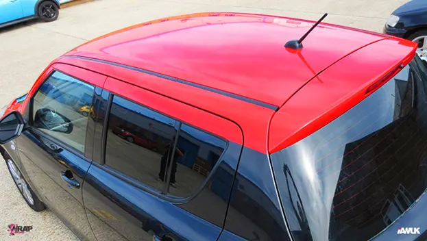
Figure 1: Automobile Roof
In later years, many variations on the automobile roof developed. These include:
- Convertible Roofs:
A Convertible is a passenger car that can be driven with or without a roof in place. The methods of retracting and storing the roof vary between models. A convertible allows an open-air driving experience, with the ability to provide a roof when required.
Modern safety features specifically for convertibles include:
- Rollover protection structures (ROPS) with pyrotechnically charged roll hoops hidden behind the rear seats that deploy under rollover conditions
- Heated rear window (for improved visibility)
- Boron steel-reinforced A-pillars
- Safety cage construction – a horseshoe-like structure around the passenger compartment
- Door-mounted side-impact airbag which inflates upward (instead of downward like the typical curtain airbag) to provide head protection even with an open window
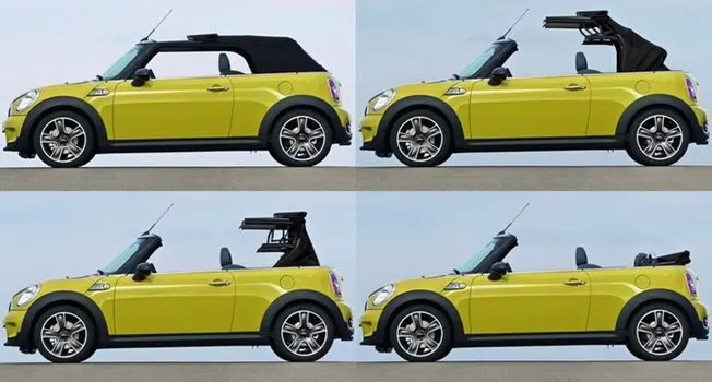
Figure 2: Convertible
- Hardtop:
A hardtop is a rigid form of automobile roof, which for modern cars is typically constructed from metal. A hardtop roof can be either fixed (i.e. not removable), detachable for separate storing or retractable within the vehicle itself. Pillarless hardtop is a body style of cars without a B-pillar, which are often styled to give the appearance of a convertible design.

Figure 3: Retractable Hardtop
- Sunroof and Moonroof:
A sunroof is a movable panel that opens to uncover a window in an automobile roof, allowing light and fresh air to enter the passenger compartment. Sunroofs can be manually operated or motor driven, and are available in many shapes, sizes and styles. A moonroof has a glass panel that is transparent and usually tinted.

Figure 4: Sunroof
- Vinyl Roof:
Vinyl roof refers to a vinyl covering for an automobile's top. This covering was originally designed to give the appearance of a convertible to models with a fixed roof, but eventually it evolved into a styling statement in its own right.

Figure 5: Vinyl Roof
Theory:
- Roof Crush Test of Passenger Car for Vehicle Safety and Crashworthiness:
Rollover accidents of a car are the most occurring accidents that we see in our daily lives. The passengers experience major injuries like neck, head and spine injuries. So, to reduce the injuries of a passenger from major fatalities it is important to provide safety in the car. Though safety is provided by seat belts and airbags during accidents, the passenger must have sufficient space for survival in the car during accidents. The roof of the car must have high strength to resist the crush force to avail the passenger some space for survival.
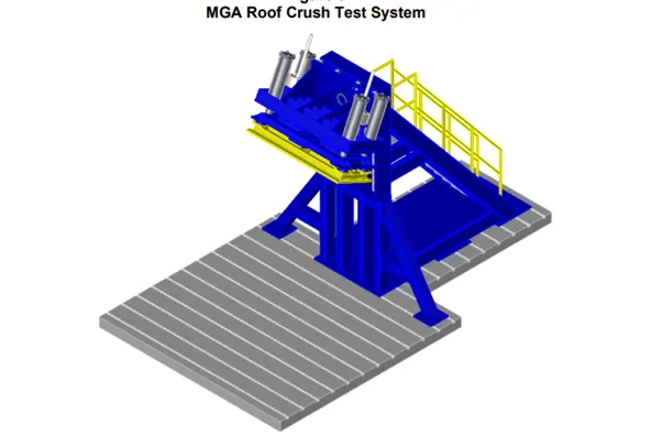
The Roof Crush Test is introduced and is carried out by the Federal Motor Vehicle Safety Standards (FMVSS 216). The rigid plate is used to crush the car roof as specified by the FMVSS 216 standards. The rigid plate is oriented on the car roof as specified by Insurance institute of highway safety (IIHS). The crashworthiness of the roof material is determined by the strength to weight ratio (SWR) of the material. The SWR is the outcome of the test results.
- FMVSS 216 Roof crush standards and Procedure of the test:
FMVSS 216, Roof Crush Resistance, establishes strength requirements for the passenger compartment roof of passenger cars, multipurpose passenger vehicles, trucks and buses with a Gross Vehicle Weight Rating (GVWR) of 2722 kilograms or less. The purpose of the standard is to reduce deaths and injuries due to the crushing of the roof into the passenger compartment in rollover accidents.
The prescribed static loading device is a rigid unyielding rectangular block 762 millimeters by 1,829 millimeters. It shall not move more than 127 millimeters to achieve the specified resistive load when applied to the forward edge of a vehicle’s roof – see Figures. The resistive load to be achieved is 1½ times the unloaded vehicle weight (UVW) of the test vehicle or 22,240 Newtons, whichever is less.
The force shall be applied in a downward direction perpendicular to the lower surface of the static loading device at a rate of not more than 13 millimeters per second until reaching the compliant resistive load. The test shall be completed within 120 seconds. The static loading device shall be guided throughout the test so that it moves, without rotation, in a straight line with its lower surface oriented as follows and as shown in Figures.
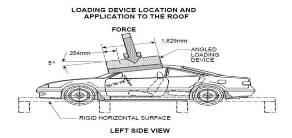
Figure 6: Static Loading Device Side View
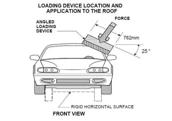
Figure 7: Static Loading Device Front View
Design in NX 12.0:
Inputs:
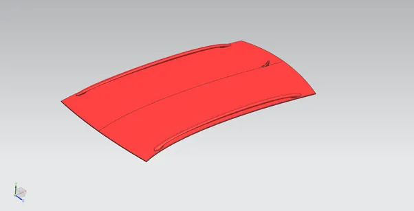
Figure 8: Styling Surface
Master Section of Rear Roof Rail:
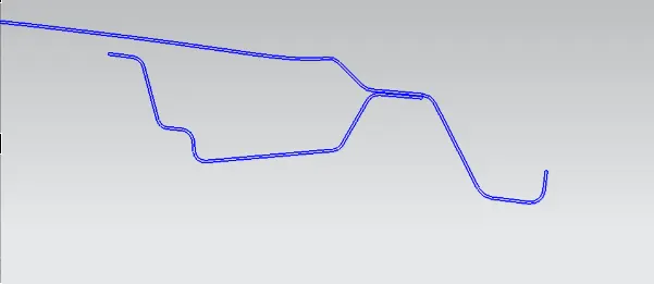
Master Section of Bow Roof:
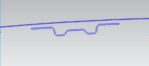
Master Section of Front Roof Rail:
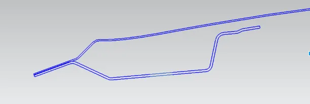
Master Section of Reinforcement Centre:
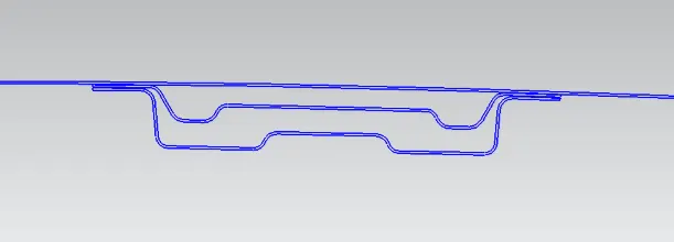
Front Roof Rail Data:
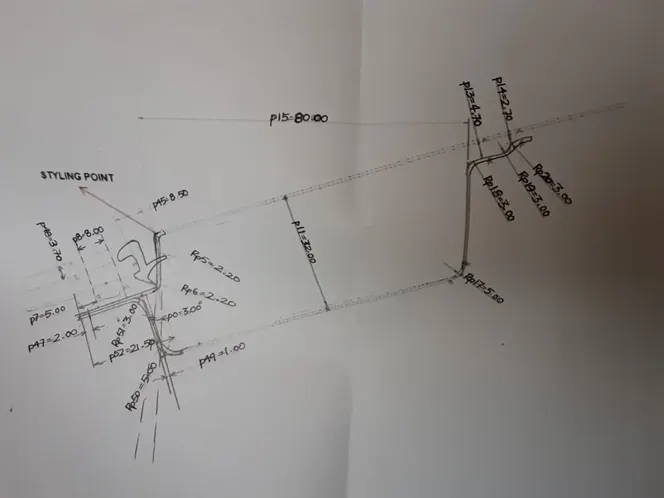
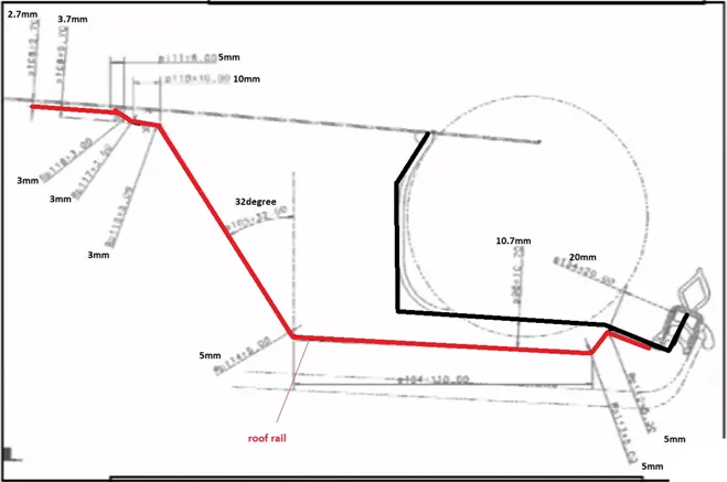
Rear Roof Rail Data:
Designed Roof:
1. Roof Outer Panel:
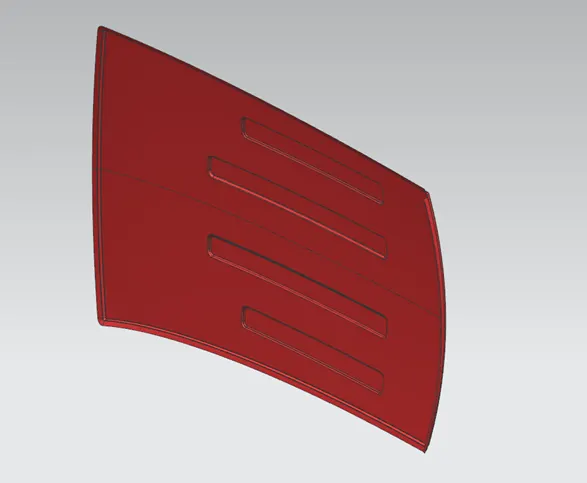
Figure 9: Trimetric View
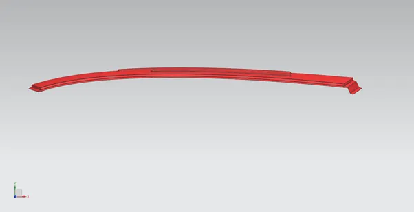
Figure 10: Top View
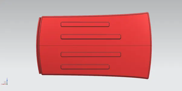
Figure 11: Back View
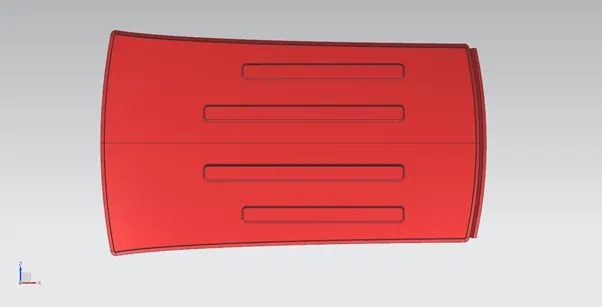
Figure 12: Front View
2. Front Roof Rail:
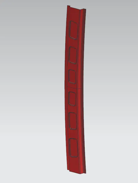
Figure 13: Trimetric View
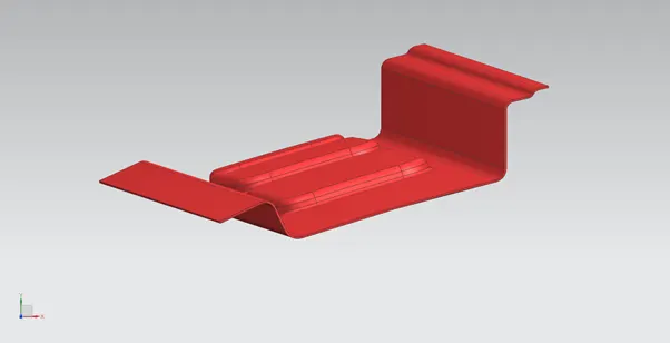
Figure 14: Top View
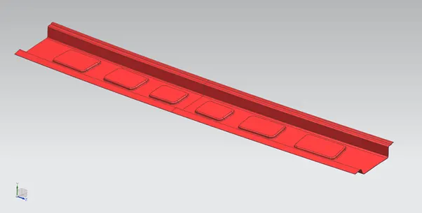
Figure 15: Isometric View
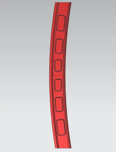
Figure 16: Front View
3. Rear Roof Rail:
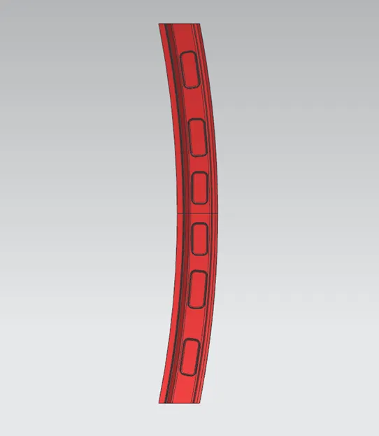
Figure 17: Front View
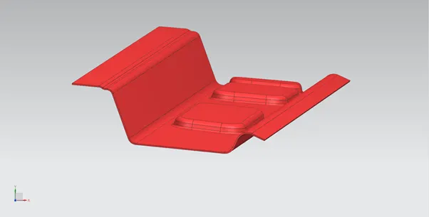
Figure 18: Top View
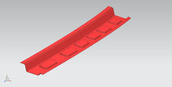
Figure 19: Isometric View
4. Bow Roof 1:
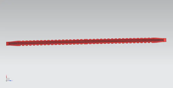
Figure 20: Top View
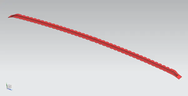
Figure 21: Isometric View
5. Bow Roof 2:
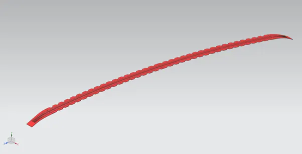
6. Centre Roof Rail:
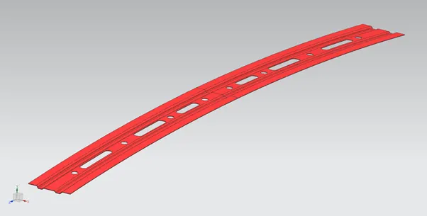
Figure 22: Trimetric View
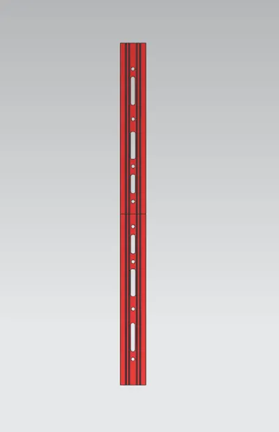
Figure 23: Front View
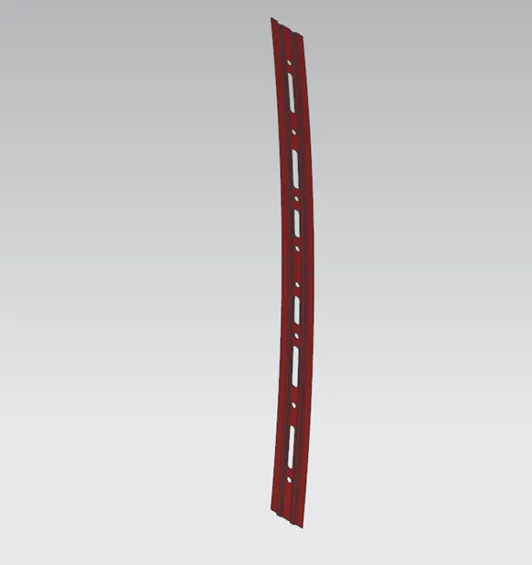
Figure 24: Isometric View
7. Centre Bow Roof:
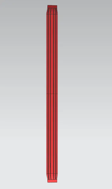
Figure 25: Front View
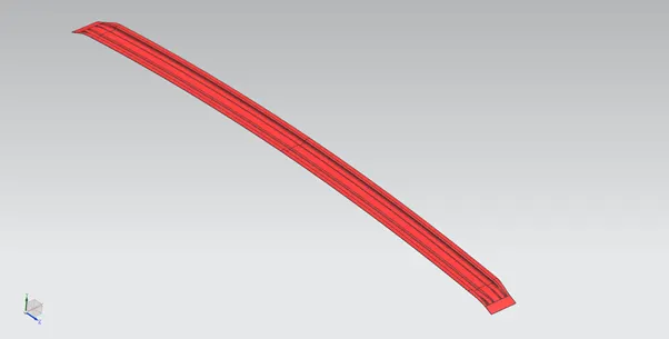
Figure 26: Isometric View
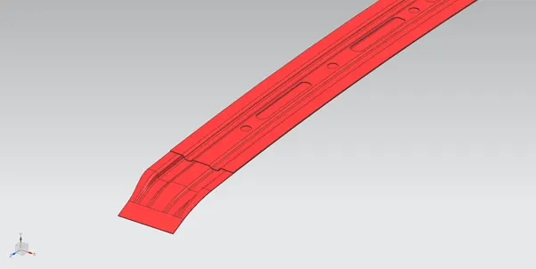
Figure 27: Centre Reinforcement
Roof Assembly:
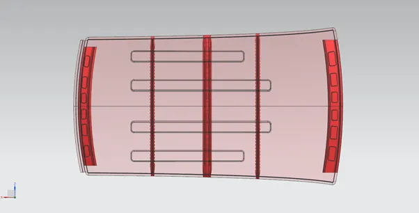
Figure 28: Back View
From left to right,
1: Front Roof Rail
2: Bow Roof 1
3: Centre Roof Reinforcement (Centre Roof Rail and Centre Bow Roof)
4: Bow Roof 2
5: Rear Roof Rail
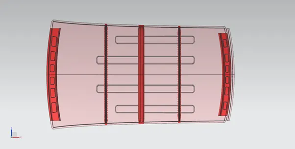
Figure 29: Front View
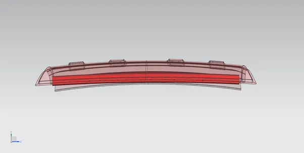
Figure 30: Side View
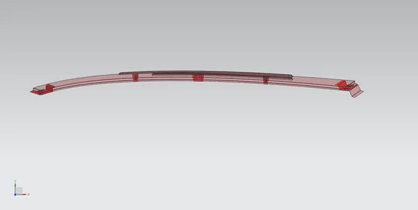
Figure 31: Top View
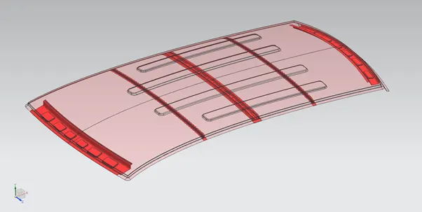
Figure 32: Isometric View
Roof Curvature Study:
- Heat Distortion criteria:
Heat distortion temperature is the temperature at which the metal softens and deforms under a specific load. This study is done to check the ability of the roof to withstand high temperature with respect to the positioning of the reinforcements which contribute to increased strength.
Bow-Roof prediction formula:
W = (1.73*10-3*L) + (1.85*10-8*R2/t) + (1.10*10-3*l) -2.68 where,
L = Roof Length in X-direction (mm) (Roof dimension in 0Y)
R = Roof Curvature,
R = (2*Rx*Ry)/(Rx+Ry)
Rx = x curvature
Ry = y curvature
t = Roof plate thickness (mm)
l = Bow Roof Span (mm)
Procedure:
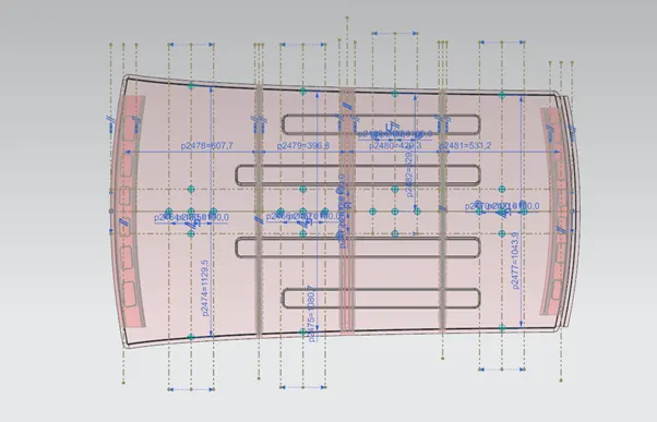
- Create the 0Y line at the centre
- From the 0Y line, create the 3Y line at 300mm offset
- Create two offset lines 100mm each from the 3Y line on either side
- Create other necessary construction and get the required intersection points
- Project the points on the Roof outer panel surface and create three- point arcs connecting all points
- Measure the Rx and Ry values
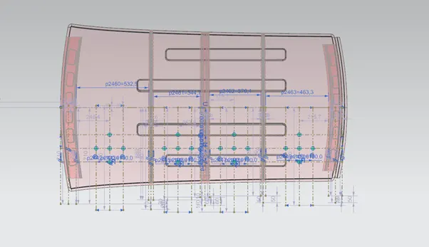
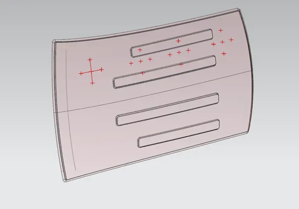
Calculations: (all dimensions are in mm)
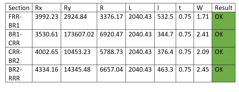
Judgement criteria: W < 2.7
- Snow load criteria:
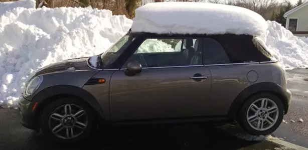
The roof should be designed in such a way that it should hold the snow on the roof (for the regions where it snows). The roof would bend slightly when the load is applied and regain its original shape when load is removed. Therefore, the roof is tested here to avoid plastic deformation under severe conditions.
Snow load prediction formula:
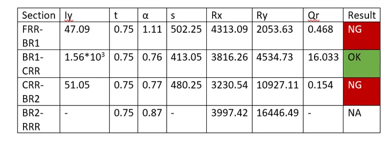
Qr = (Iy*t2)/(α*s*((Rx+Ry)/2)2 *10-8)
Where, α = My*Lx2*10-12, My = Y(Ly-Y)
t = Roof plate thickness (mm)
Ly = Distance between the front and rear roof Rails on the Vehicle along with 0Y[mm]
Length of Roof panel with the centre point between Roof rail Front /Rear as the front and rear reference point.
Lx = Distance between the Left and Right end of the roof on the Roof BOW [mm]
Width of the roof panel exposed on the surface.
Y = Distance from Front Roof Rail centre to Roof BOW [mm]
s = Distance for which Roof BOW bears divided load [mm]
s = L1/2 + L2/2
Iy = Geometrical moment of inertia of Roof BOW (Y cross-section) [mm4]
Rx = Lateral direction curvature radius of roof panel Y cross-section on Roof BOW [mm]
Roof panel curvature Radius of the Length Lx in Front view
Ry = Longitudinal Direction curvature radius of the Roof panel X cross-section on Roof BOW [mm]
Roof panel X curvature radius of length s in Side view
Judgement condition: Qr >= 3.1
Section Inertia Analysis:
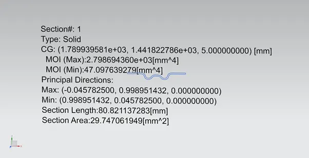
Figure 33: Bow Roof 1
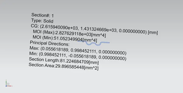
Figure 34: Bow Roof 2
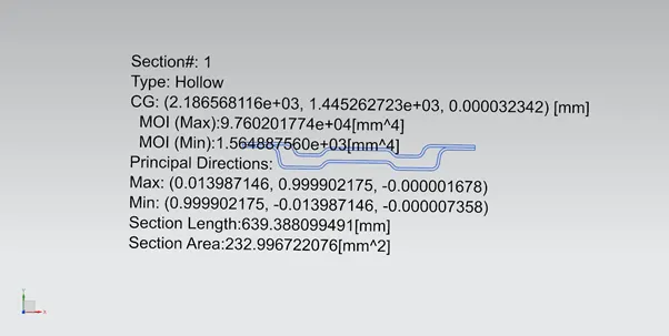
Figure 35: Centre Roof Rail
Draft Analysis:
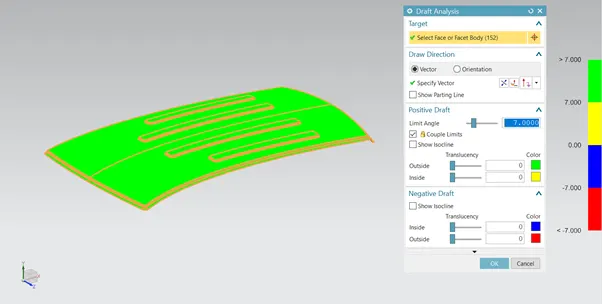
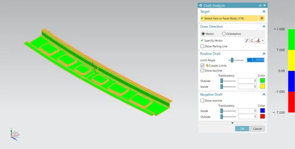
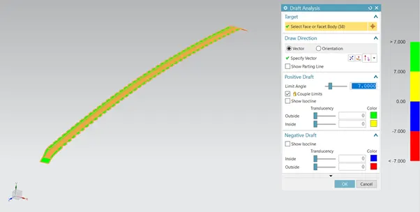
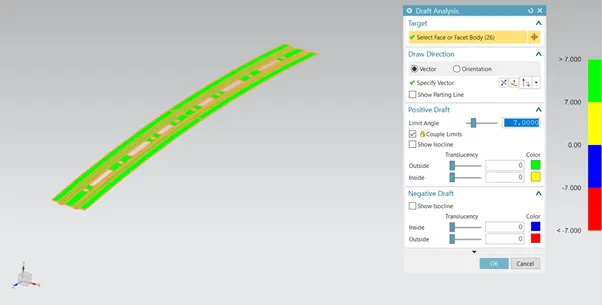
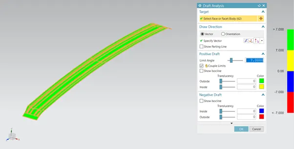
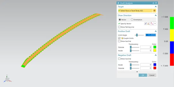
The ditch area flanges and remaining features are created using the following tools/commands in NX 12.0:
- Extract Geometry
- Untrim
- Trim Sheet
- Offset Surface
- Extend Sheet
- Bridge Curve
- Law Extension
- Trim and Extend
- Datum Plane
- Intersection Curves
- Offset in face
- Through curves
- Sew
- Edge Blend
- Face Blend
- Studio Surface
- Projected Curve
- Emboss
- Mirror Geometry
- Thicken
Conclusion: Thus, the Roof is designed as per the industry standards and checked for the Heat Distortion and Snow Load criterion. The designed roof was found to satisfy the Heat Distortion criteria whereas it failed the Snow Load criteria due to which embosses were created on the surface to provide extra strength. Alternatively, the position of bow roofs can be changed as well. The Draft Analysis of the designed roof was carried out where it was found that it satisfies the minimum drawing angle required for sheet metal components (7 degrees). The Assemblies, Surface, Analysis and Curve workbenches of NX 12.0 have been used for this project.