American Chopper
Project Report
Title: Surface Modeling, Solid Modeling and Photo Realistic Rendering of an American Chopper using SolidWorks 2020 and PhotoView 360
Introduction:
SolidWorks is a solid modeling computer-aided design and computer-aided engineering computer program. SOLIDWORKS is the most widely used 3D CAD package in education and industry today. SolidWorks utilizes a parametric feature-based approach.
- Modeling Technology
Parameters refer to constraints whose values determine the shape or geometry of the model or assembly. Parameters can be either numeric parameters, such as line lengths or circle diameters, or geometric parameters, such as tangent, parallel, concentric, horizontal or vertical, etc. Numeric parameters can be associated with each other through the use of relations, which allows them to capture design intent.
Design intent is how the creator of the part wants it to respond to changes and updates. For example, you would want the hole at the top of a beverage can to stay at the top surface, regardless of the height or size of the can. SolidWorks allows the user to specify that the hole is a feature on the top surface, and will then honor their design intent no matter what height they later assign to the can.
Features refer to the building blocks of the part. They are the shapes and operations that construct the part. Shape-based features typically begin with a 2D or 3D sketch of shapes such as bosses, holes, slots, etc. This shape is then extruded to add or cut to remove material from the part. Operation-based features are not sketch-based, and include features such as fillets, chamfers, shells, applying draft to the faces of a part, etc.
Building a model in SolidWorks usually starts with a 2D sketch. The sketch consists of geometry such as points, lines, arcs, and splines. Dimensions are added to the sketch to define the size and location of the geometry. Relations are used to define attributes such as tangency, parallelism, perpendicularity, and concentricity. The parametric nature of SolidWorks means that the dimensions and relations drive the geometry, not the other way around. The dimensions in the sketch can be controlled independently, or by relationships to other parameters inside or outside the sketch.
In an assembly, the analog to sketch relations are mates. Just as sketch relations define conditions such as tangency, parallelism, and concentricity with respect to sketch geometry, assembly mates define equivalent relations with respect to the individual parts or components, allowing the easy construction of assemblies.
- SolidWorks 2020 commonly used Solid features
- Extruded Boss/Base: Extrudes a sketch or selected sketch contours in one or two directions to create a solid feature.
- Revolved Boss/Base: Revolves a sketch or selected sketch contours around an axis to create a solid feature.
- Swept Boss/Base: Sweeps a closed profile along an open or closed path to create a solid feature.
- Lofted Boss/Base: Adds material between two or more profiles to create a solid feature.
- Extruded Cut: Cuts a solid model by extruding a sketched profile in one or two directions.
- Revolved Cut: Cuts a solid model by revolving a sketched profile around an axis.
- Swept Cut: Cuts a solid model by sweeping a closed profile along an open or closed path.
- Fillet: Creates a rounded internal or external face along one or more edges on a solid or surface feature.
- Chamfer: The chamfer tool creates a beveled feature on selected edges, faces, or a vertex.
- Linear Pattern: Patterns features, faces, and bodies in one or two linear directions.
- Circular pattern: Create circular sketch patterns on a plane or on a model using sketch entities or model edges to define the pattern.
- Curve Driven Pattern: The Curve Driven Pattern tool allows you to create patterns along a planar or 3D curve.
- Shell: Hollows out a part, leaving open the faces you select, and creating thin-walled features on the remaining faces.
- Mirror: Mirror features, faces and bodies about a plane or a planar face.
- Trim and Extend Entities: Trims or extends a sketch entity to be coincident to another, or deletes a sketch entity. The power trim option lets you trim adjacent entities simply by dragging across them.
- Convert Entities: Converts selected edges and sketch entities into identical entities by projecting them onto the sketch plane or face.
- Offset entities: Offsets one or more sketch entities by a specified distance. If the original entity changes, then the offset entity also changes when you rebuild the model.
- Mirror Entities: Mirrors selected entities about a centerline or planar reference.
- Linear Sketch Pattern: Adds a linear pattern of sketch entities.
- Smart Dimension: Creates a dimension for one or more selected entities.
- SolidWorks 2020 Surface features
- Extruded Surface: Extrudes a sketch or selected sketch contours in one or two directions to create a surface feature.
- Revolved Surface: Revolves a sketch or selected sketch contours around an axis to create a surface feature.
- Swept Surface: Sweeps a closed profile along an open or closed path to create a surface feature.
- Lofted Surface: Creates a lofted surface between two or more profiles or sketches.
- Filled Surface: Patches a surface within a boundary defined by edges, sketches, or curves.
- Offset Surface: Offsets surfaces using one or more contiguous faces.
- Ruled Surface: Inserts ruled surfaces in a specified direction from edges. Select tangent to surface, normal to surface, tapered to vector, perpendicular to vector, or sweep.
- Extend Surface: Extends one or more edges or faces on a surface.
- Trim Surface: Trims where a surface intersects with another surface, a plane or a sketch. Select a trim type, trim tool, and the surfaces to keep or remove.
- Knit Surface: Combines two or more adjacent, nonintersecting surfaces into a single surface body. The surfaces must join at an edge. If the resulting knit surface encloses a volume, you can create a solid body.
Objectives:
The main objectives of this project are:
- To create individual parts of an American Chopper using Solid Modeling and Surface Modeling tools and techniques in SolidWorks 2020
- To assemble all the individual parts and create the Chopper
- To give appearances to individual parts
- To make use of decals
- To create a photorealistic model by rendering on PhotoView 360
Design Methodology: The Design Methodology used in this project is top-down approach.
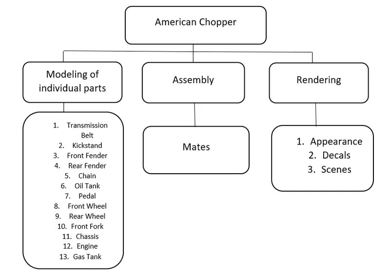
Parts of American Chopper:
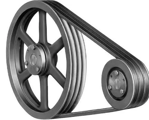
- Transmission Belt: A belt is a loop of flexible material used to link two or more rotating shafts mechanically, most often parallel. Belts may be used as a source of motion, to transmit power efficiently. Belts are looped over pulleys and may have a twist between the pulleys, and the shafts need not be parallel.
CAD Model of Transmission Belt on SolidWorks 2020:
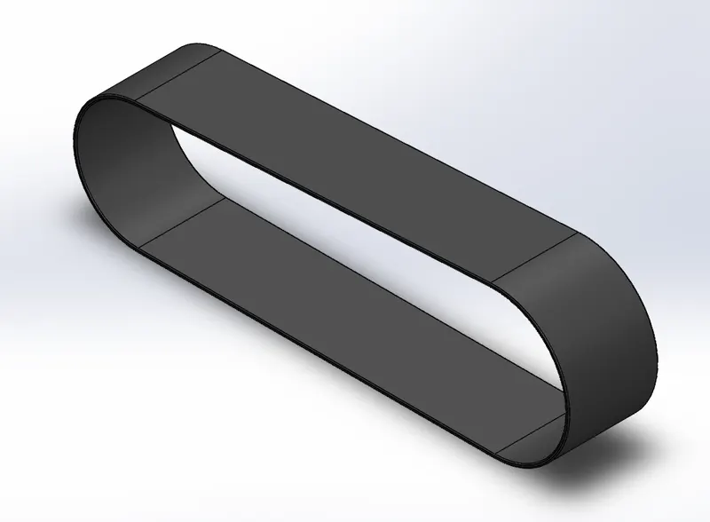
Features used to create the Transmission Belt in SolidWorks 2020:
- Boss Extrude
- Fillet
2. Kickstand: A kickstand is a device on a bicycle or motorcycle that allows the bike to be kept upright without leaning against another object or the aid of a person. A kickstand is usually a piece of metal that flips down from the frame and makes contact with the ground. It is generally located in the middle of the bike or towards the rear.
CAD Model of Kickstand on SolidWorks 2020:
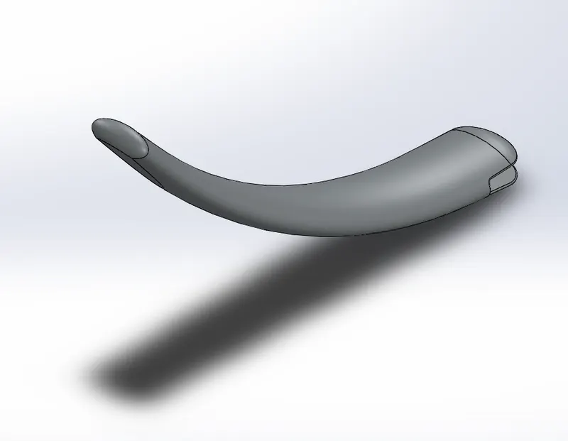
Features used to create the Kickstand in SolidWorks 2020:
- Loft
- Dome
- Cut Extrude
- Split
- Boss Extrude
- Fillet
3. Front Fender:
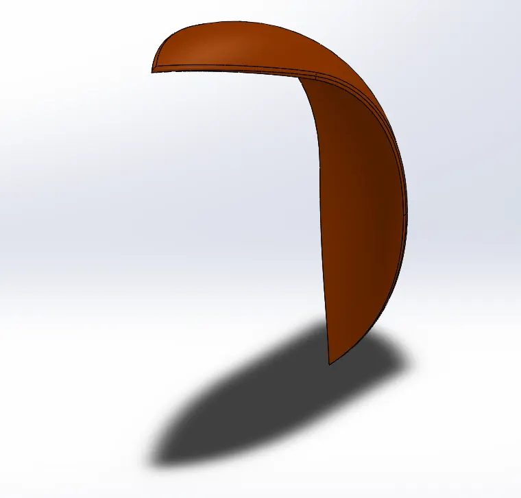
Figure 1: CAD Model of Front Fender
Features used to create the Front Fender in SolidWorks 2020:
- Revolve
- Split
- Fillet
4. Rear Fender:
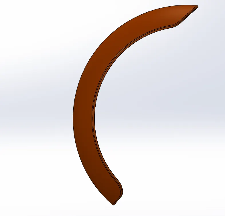
Figure 2: CAD Model of Rear Fender
Features used to create the Rear Fender in SolidWorks 2020:
- Revolve
- Split
- Fillet
- Shell
5. Chain:
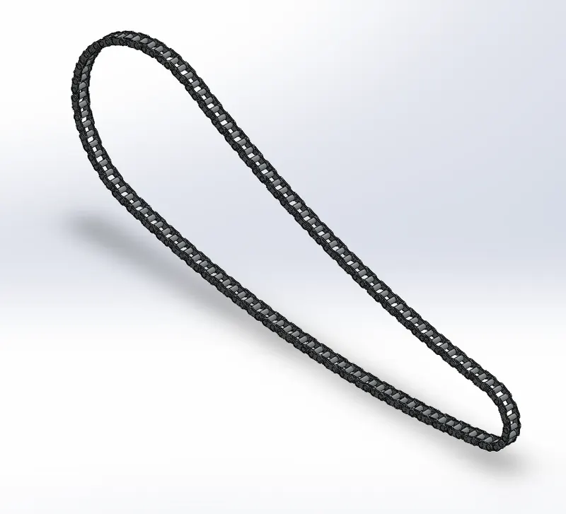
Figure 3: CAD Model of Chain
Features used to create the Chain in SolidWorks 2020:
- Boss Extrude
- Fillet
- Curve Driven Pattern
- Mirror
- Delete/Keep Body
6. Oil Tank:
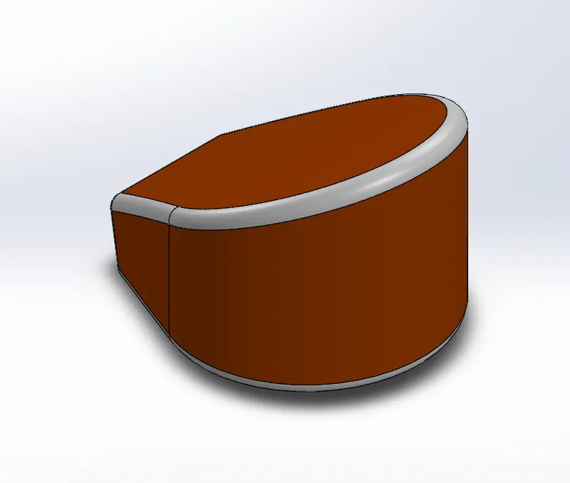
Figure 4: CAD Model of Oil Tank
Features used to create the Oil Tank in SolidWorks 2020:
- Boss Extrude
- Combine
- Fillet
- Shell
7. Pedal:
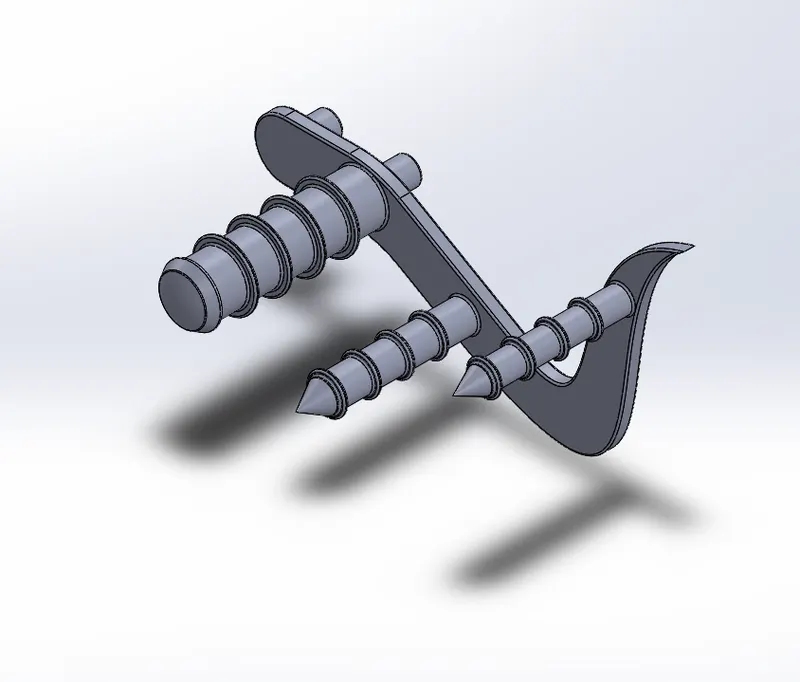
Figure 5: CAD Model of Pedal
Features used to create the Pedal in SolidWorks 2020:
- Boss Extrude
- Fillet
- Revolve
- Dome
- Chamfer
- Linear Pattern
8. Front Wheel: For the Front Wheel the Disc Rotor, Brake Calliper, Wheel Rim and Tire along with the tread were modelled.
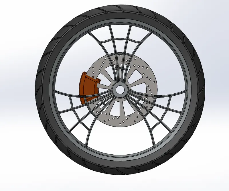
Figure 6: Side View
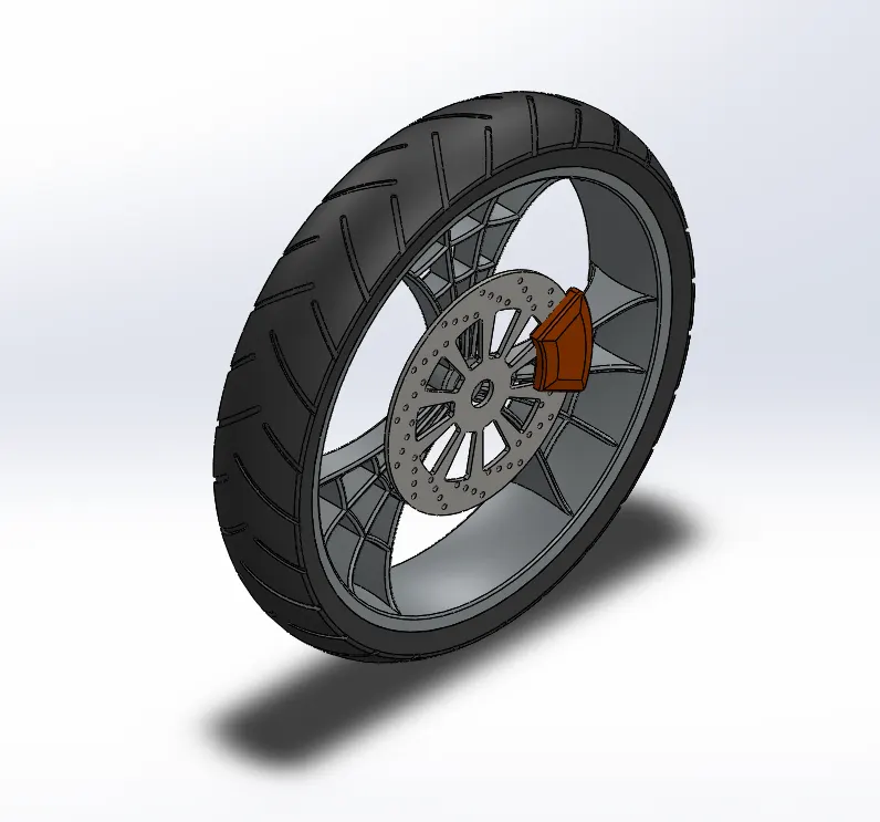
Figure 7: Isometric View
Features used to create the Front Wheel in SolidWorks 2020:
- Revolve
- Boss Extrude
- Cut Extrude
- Cut Revolve
- Circular Pattern
- Combine
- Fillet
- Chamfer
9. Rear Wheel: For the Rear Wheel the Disc Rotor, Wheel Rim, Brake Calliper, Sprocket and the Tire along with the tread were modelled.
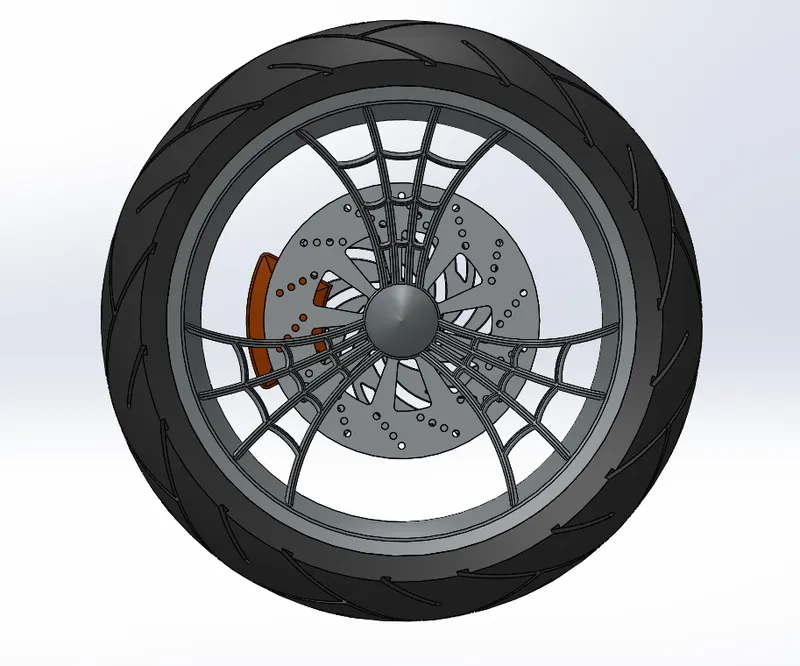
Figure 8: Front View
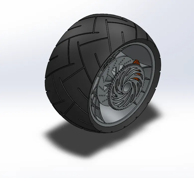
Figure 9: Isometric View
Features used to create the Rear Wheel in SolidWorks 2020:
- Revolve
- Boss Extrude
- Cut Extrude
- Circular Pattern
- Combine
- Revolve Cut
- Fillet
- Chamfer
10. Front Fork: The Front Fork acts as the Steering of the Chopper. For the Front Fork the handlebars, grips, handles, brake cables and the lights were modelled.
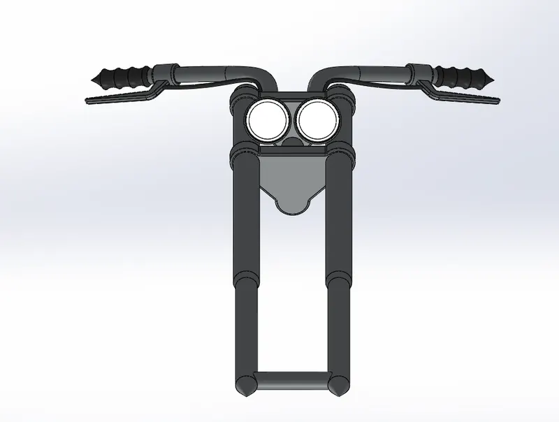
Figure 10: Front View
Features used to create the Front Fork in SolidWorks 2020:
- Revolve
- Boss Extrude
- Fillet
- Linear Pattern
- Cut Extrude
- Dome
- Cut Revolve
- Body Move/Copy
- Projected Curves
- Sweep
- Mirror
- Combine
11. Chassis: The Chassis is the main frame(body) of the Chopper. Various mounting plates were modelled on the Chassis to support the Chopper.
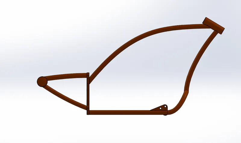
Figure 11: Front View
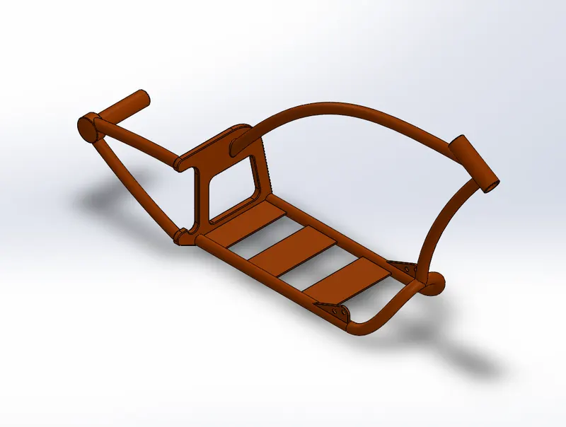
Figure 12: Isometric View
Features used to create the Chassis in SolidWorks 2020:
- Insert Image- Blueprint
- Projected Curves
- Sweep
- Mirror
- Boss Extrude
- Cut Extrude
- Chamfer
- Fillet
- Dome
- Split
- Combine
- Revolve
12. Engine: The Engine is the heart of the Chopper like any other vehicle. For the Engine, the motor, cylinders, transmission belt pulleys, smaller sprocket, air filter, exhaust pipes and the spark plug cables were modelled.
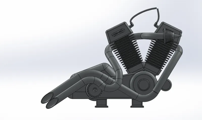
Figure 13: Front View
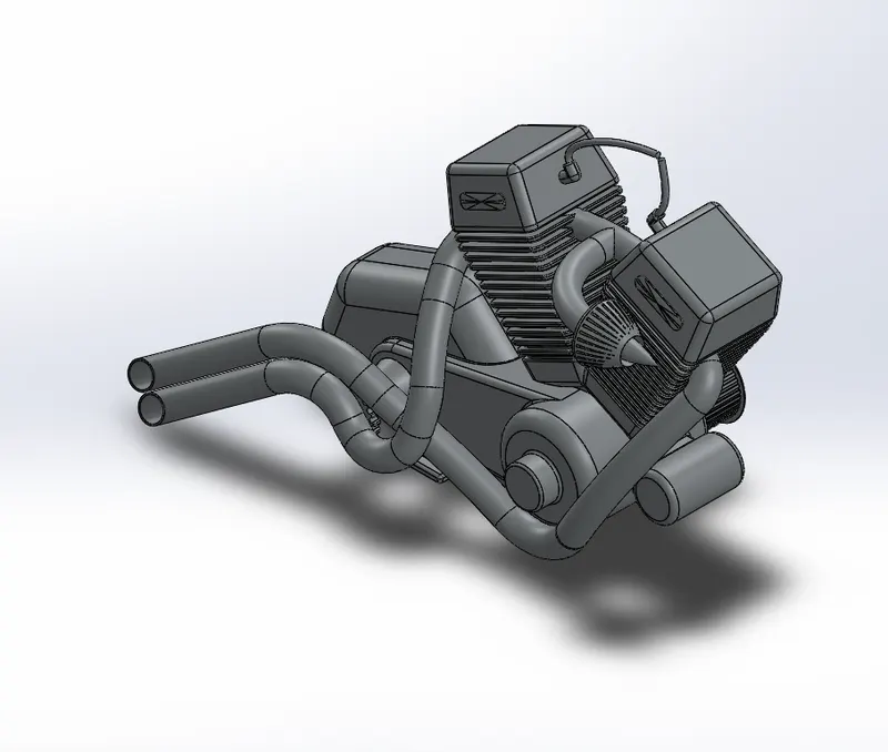
Figure 14: isometric View
Features used to create the Engine in SolidWorks 2020:
- Insert Image- Blueprint
- Boss Extrude
- Fillet
- Revolve
- Circular Pattern
- Dome
- Cut Extrude
- Chamfer
- Linear Pattern
- Mirror
- Split
- Sweep
- Combine
- Projected Curves
- Composite Curves
13. Gas Tank: The seat was modelled with the gas tank.
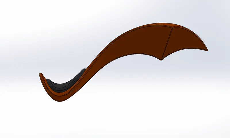
Figure 15: Front View
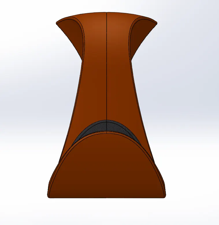
Figure 16: Side View
Features used to create the Gas Tank in SolidWorks 2020:
- Surface Sweep
- Surface Trim
- Projected Curve
- Surface Loft
- Boundary Surface
- Mirror
- Surface Knit
- Split Line
- Surface Extrude
- Fillet
- Cut Sweep
- Shell
Assembly of American Chopper:
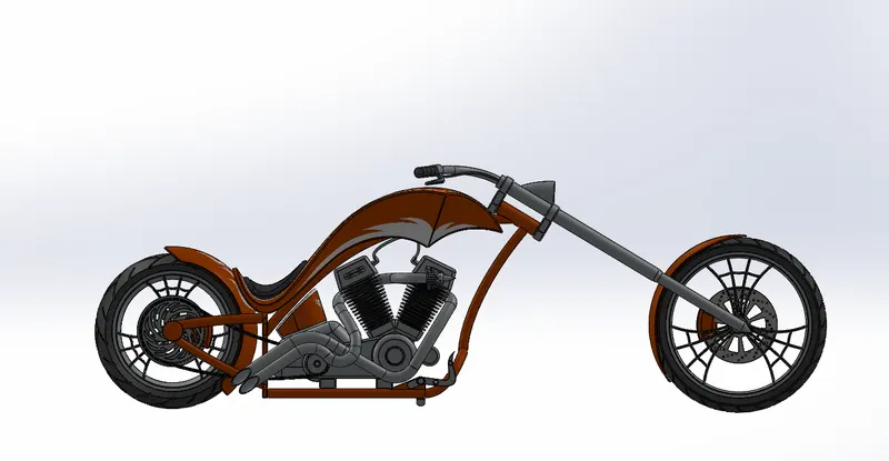
Figure 17: Front View
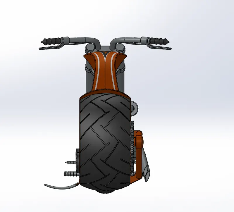
Figure 18: Side View
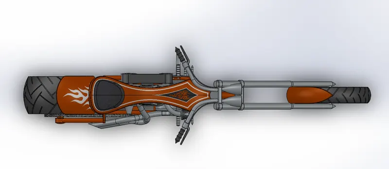
Figure 19: Top View
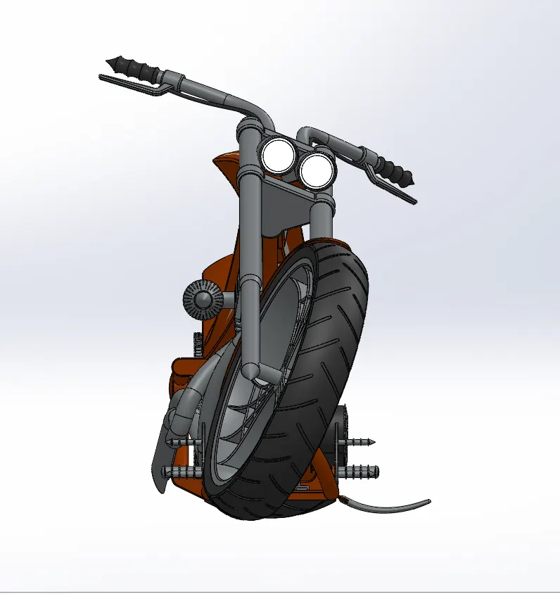
Figure 20: Right View
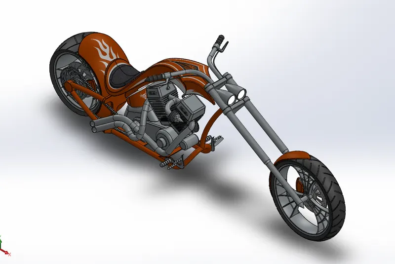
Figure 21: Isometric View
For creating the assembly, individual parts were inserted and were either fixed or defined by giving mates as constraint. The Chassis was fixed and other parts were given mates as follows.
The Engine was given the following constraints/mates:
- Coincident
- Distance
- Concentric
- Width
- Angle
The Kickstand was given the following mates:
- Coincident
- Concentric
- Limit Angle
The Transmission Belt was given the following mates:
- Concentric
- Width
- Angle
The Oil Tank was given the following mates:
- Coincident
The Rear Wheel was given the following mates:
- Concentric
- Coincident
- Parallel
- Width
The Rear Fender was given the following mates:
- Concentric
- Coincident
- Parallel
The Chain was given the following mates:
- Width
- Concentric
- Parallel
The Gas Tank was given the following mates:
- Distance
- Coincident
The Front Fork was given the following mates:
- Concentric
- Width
- Limit Angle
- Coincident
The Front Wheel was given the following mates:
- Concentric
- Coincident
The Front Fender was given the following mates:
- Coincident
The Pedal was given the following mates:
- Concentric
- Coincident
The Pedal was then mirrored
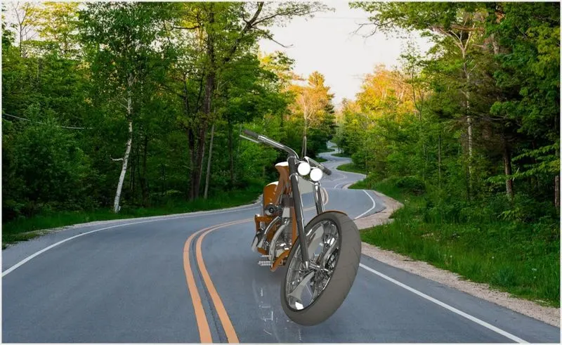
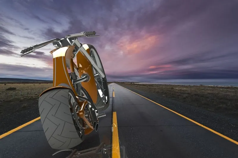
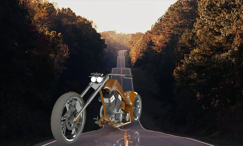
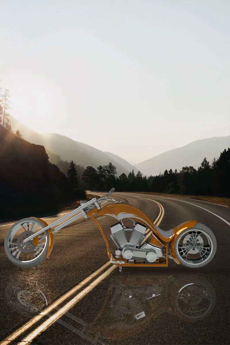
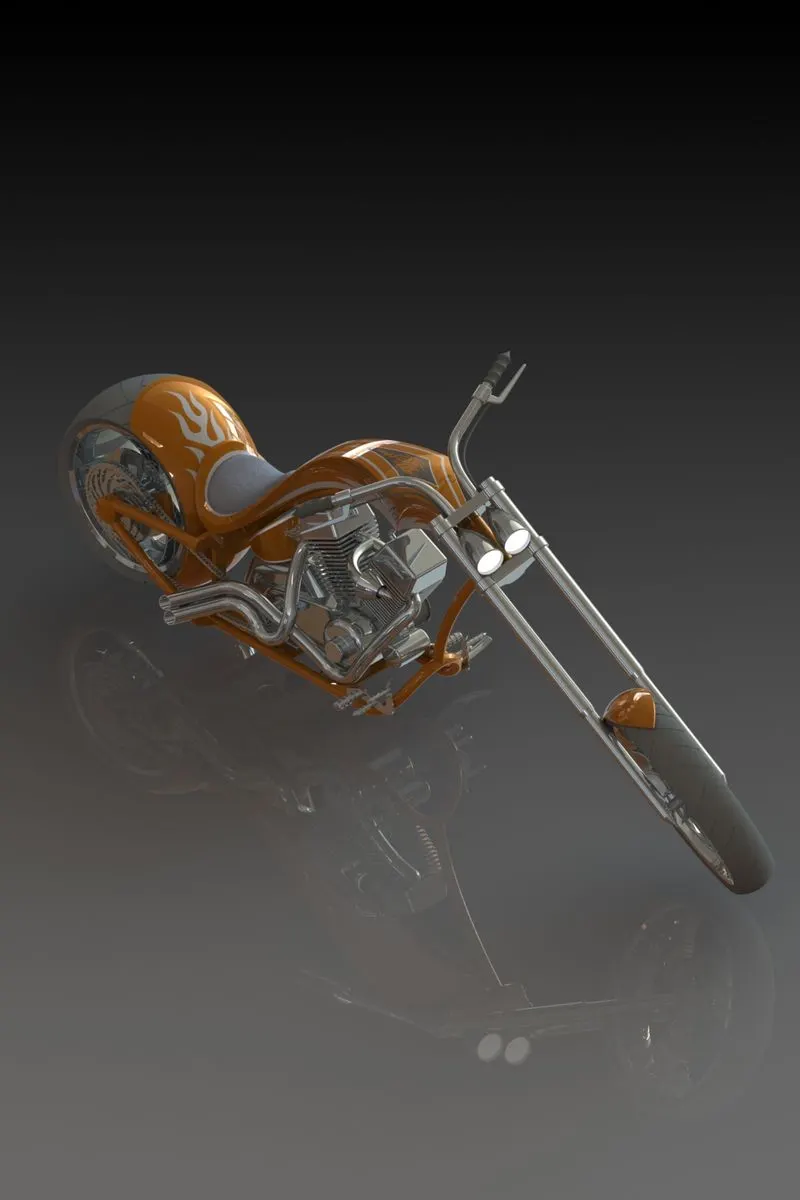
Rendering of American Chopper on PhotoView 360:
Conclusion:
- The individual parts of the Chopper are modelled
- The parts are inserted to create the assembly
- The assembly is rendered to create a photorealistic image