Week 9 - Attachment Feature Creation - Challenge 2
Screw Boss Design
Bosses find use in many part designs as points for attachment and assembly. The most common variety consists of cylindrical projections with holes designed to receive screws, threaded inserts or other types of fastening hardware. As a rule of thumb, the outside diameter of bosses should remain 2 to 2.4 times the outside diameter of the screw or insert.
Avoid Bosses that merge into sidewalls because they can form thick sections that lead to sink. Instead position the bosses away from the sidewall, and if needed use connecting ribs for support. Consider using open boss designs for bosses near a standing wall.
Normally, the boss hole should extend to the base wall level, even if the full depth is not needed for assembly. Shallower holes can leave thick sections, resulting in sink or voids. Deeper holes reduce the base wall thickness, leading to filling problems, knit lines, or surface blemishes. The goal is to maintain a uniform thickness in the attachment wall. Because of the required draft, tall bosses- those greater than five times their outside diameter- can create a filling problem at their top or a thick section at their base.
Design Rules for Screw Boss:
The Screw Boss is designed keeping in mind the following rules
- Draft = 0.5 deg inside and outside
- Thickness, w = 0.6*T where 'T' is the base wall thickness
- Height to Diameter Ratio = 3:1
- Optional radii = 0.25mm maximum
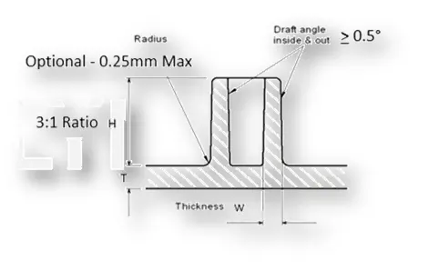
Calculations:
The following calculations are carried out for designing a screw boss for M6 screw
- Thickness = 0.6*T = 0.6*2.5= 1.5mm
- Optional radii = 0.25mm maximum on all faces
- Draft = 0.5 deg inside and outside
- Inside hole dia of screw boss = 5.2mm for M6 screw
- Outer circle dia of screw boss is calculated as, D= 2*Screw Boss Thickness + Inner dia = 1.5 + 1.5 + 5.2 = 8.2mm
- Height of screw boss = 12mm
- The height of supporting ribs should be less than the height of screw boss. Hence, height of supporting ribs = 10mm
- The supporting ribs should be designed as per the design rules for rib design.
- Rib thickness = 0.4*t = 0.4*2.5 = 1mm
- Minimum draft angle = 0.5 deg
- Rib fillet radius = 0.25mm
Dog House Design
Dog House serves the following purposes:
- To avoid sink marks
- When screw boss is to be perpendicular to the Tooling Axis
- When the length of the screw boss is too much
The guidelines that are followed for Dog House design are:
- Minimum draft for doghouses is 1.5 degrees
- Doghouse wall thickness at intersection of part wall (C) should be 40% or less than the main wall stock(T)
- Height of B should be between 3-6mm
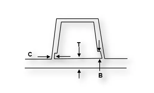
"C" is where the doghouse contacts backside of surface
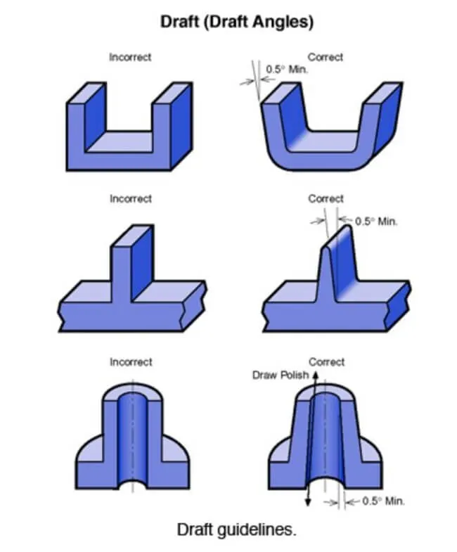
For successfully creating a component that is moldable or in other words that can be manufactured, Draft Analysis of the component should be carried out.
- What is a Draft?
Essentially, draft angles for injection molding are a design consideration that makes it much easier for a part to release cleanly from a mold. A draft angle is calculated as a degree measurement from the vertical axis of a mold, and it helps account for thermoplastic shrinkage, a practical reality of the injection molding process for most materials.
By accounting for thermoplastic shrinkage during the cooling process, draft angles greatly reduce friction between the finished, cooled part and the side of the mold. Not only does this create a much easier release process, it offers several other benefits, depending on the design of the part:
- Reduces the chance of damage to the part due to friction during release
- Reduces wear and tear and chances of damage to the mold
- Ensures a uniform, smooth, unscratched finish when required
- Ensures the integrity and uniformity of other surface finishes and textures
- Reduces overall cooling time by lessening or eliminating the need for unconventional ejection setups
- Most, if not all, of these benefits offer either direct or indirect overall production cost reductions
Steps for creating the Tooling Axis:
- The first and foremost step for conducting the Draft Analysis is to create the Tooling Axis. The Tooling Axis is the direction in which the mold opens and closes.
- The Main Tooling Axis is created along the Y direction
- The side core axis is required to clear the inner faces of the doghouse. The side core axis is created along the Z direction
- Once the main Tooling Axis and the side core axis is created, publish the Tooling Axes.
Steps for Draft Analysis:
- Go to Views and Customize View Parameters. Change to material.
- Click the Draft Analysis tool and use the compass to define the draft direction as the main tooling Axis.
- Once placed correctly, lock the draft direction.
- Now, since the minimum draft angle for ribs and screw bosses is 0.5 deg and for doghouse is 1.5 deg, define the value as 0.45 deg considering the tolerance and select the component
- The Draft Analysis is completed
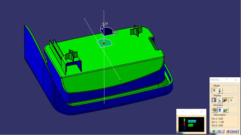
Draft Analysis along the Main Tooling Axis

Draft Analysis along the Side core axis
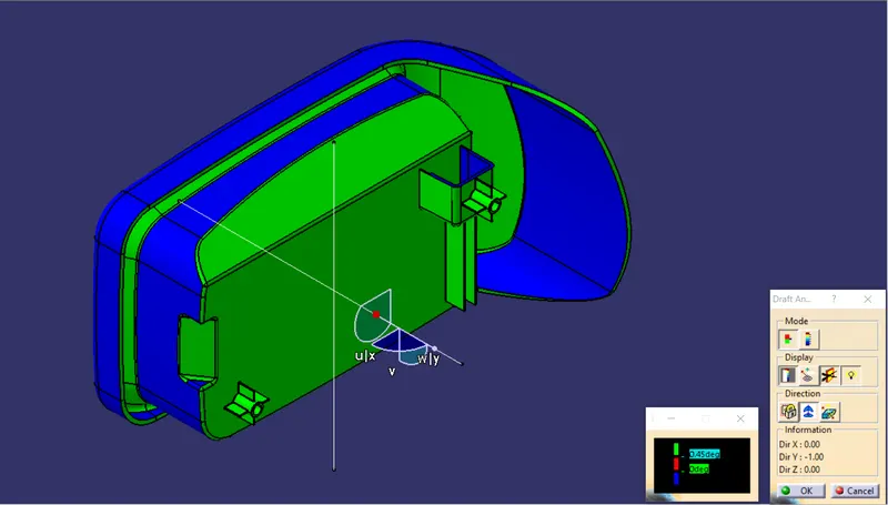
Isometric View
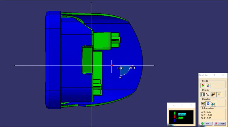
Front View
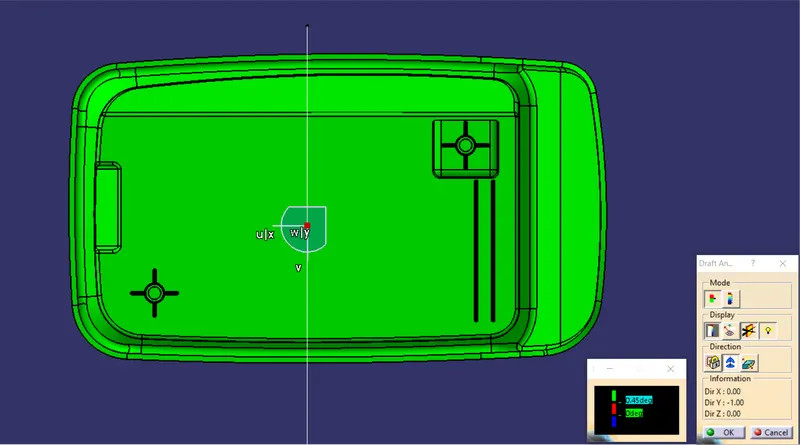
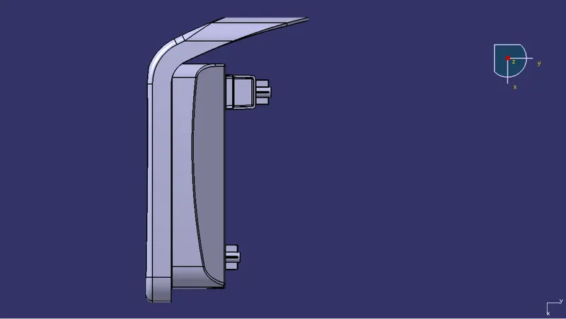
Side View
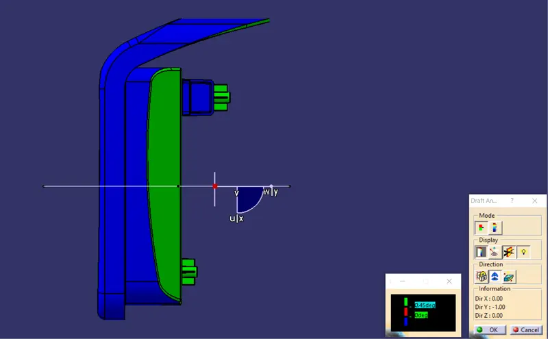
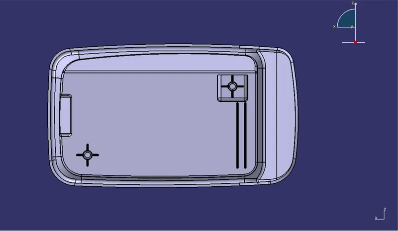
Top View
Results/ Conclusion of the Draft Analysis: By referring to the colour scale, the minimum draft angle of 0.45 deg is achieved and the component can be manufactured. The running point analysis tool can be used to find the value of draft angle at any point. The outer faces of the doghouse would be cleared by the main tooling axis and the inner faces would be cleared by the side core axis.
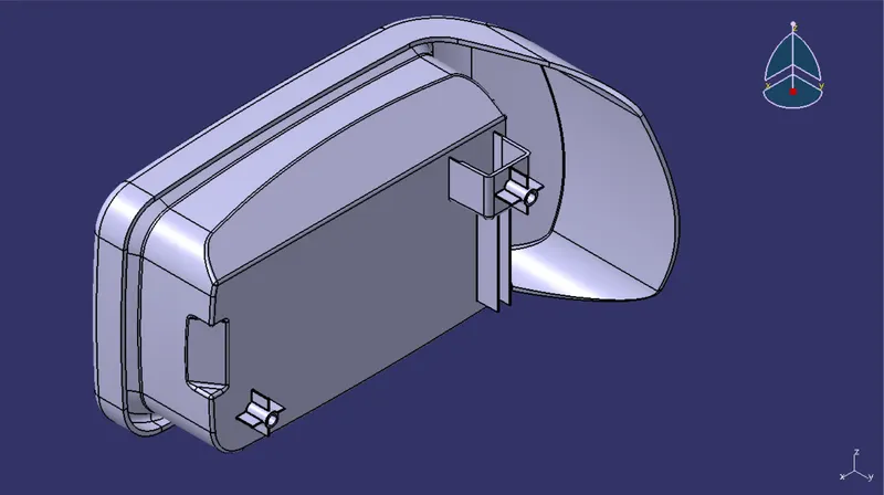
Isometric View
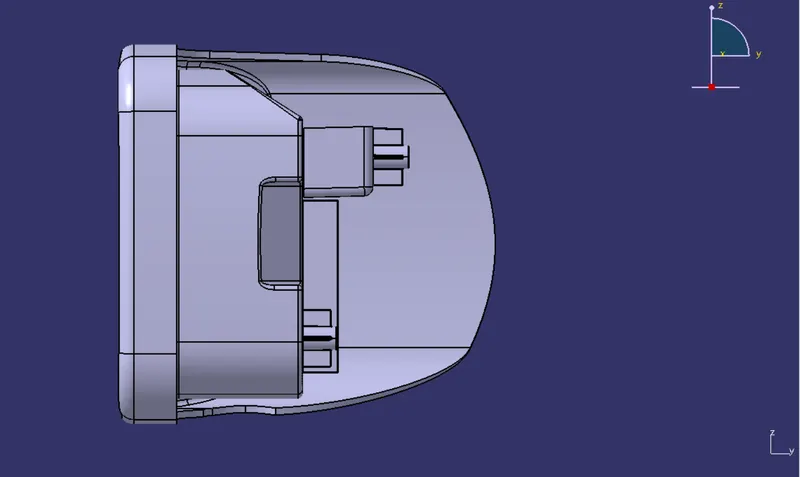
Front View
Side View
Top View