Week 9 - Attachment Feature Creation - Challenge 1
Rib Design
Ribs provide a means to economical stiffness and strength in molded parts without increasing the overall wall thickness. They also facilitate:
- Locating and arresting components of an assembly
- Providing alignment in mating parts
- Acting as stops or guides for mechanisms
Proper Rib Design involves the following considerations on Show Surfaces:
- Draft
- Thickness
- Height
- Spacing between two Ribs
- Thickness at top
- Optional fillet radius
Rib Thickness: Thick ribs often cause sink mark and in turn cosmetic problems on the opposite surface of the wall to which they are attached. The material, rib thickness, surface texture, colour, proximity to a gate, and a variety of processing conditions determine the severity of sink.
Highly glossy, critical surfaces may require thinner ribs. Thin-walled parts (<1.5mm) can often tolerate ribs that are thicker than the percentages in these guidelines. On parts with wall thicknesses that are 1mm or less, the rib thickness should be equal to the wall thickness.
Rib thickness also directly affects moldability. Very thin ribs can be difficult to fill. Because of flow hesitation, thin ribs near the gate can sometimes be more difficult to fill than those further away.
Flow entering the thin ribs hesitates and freezes while the thicker wall sections fill. Ribs usually project from the main wall in the mold-opening direction. To facilitate part ejection from the mold, ribs generally require at least one-half degree of draft per side. More than one deg of draft per side can lead to excessive rib thickness reduction and filling problems in tall ribs.
Rib Size generally, taller ribs provide greater support. To avoid mold filling, venting and ejection problems, standard rules of thumb limit rib height to approximately 5* the rib-base thickness. Because of the required draft for ejection, the tops of tall ribs may become too thin to fill easily.
Additionally, very tall ribs are prone to buckling under load. In such conditions, consider designing two or more shorter, thinner ribs to provide the same support with improved moldability. Maintain enough space between ribs for adequate mold cooling, for short ribs allow at least two times the wall thickness.
Design Rules for Rib Design:
The Rib is designed keeping in mind the following rules
- Rib thickness, w = 0.4*t where 't' is the wall thickness
- Minimum draft angle = 0.5 deg per side
- Rib thickness at tip = 0.75mm
- Rib fillet radius = 0.25 maximum
- Rib height <= 5* nominal wall thickness
- Spacing between two ribs = max 3:1 ratio, preferred ratio = 2:1
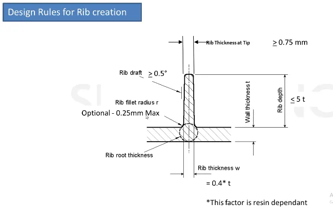
Calculations:
- Minimum draft angle = 0.5 deg per side
- Rib thickness, w= 0.4*2.5 = 1mm
- Rib thickness obtained at tip = 0.786mm
- Rib fillet radius = 0.25mm
- Rib height = 5*2.5 = 12.5mm
- Spacing between two ribs = Rib height/Ratio = 12.5/2 = 6.25 + rib thickness = 6.25+1 = 7.25mm considering a 2:1 ratio
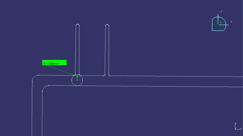
- The Rib root thickness is measured by creating an intersection and inserting a Tritangent Circle as shown in the figure. The value is found to be dia 2.686mm which is acceptable.
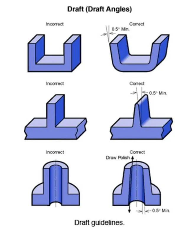
For successfully creating a component that is moldable or in other words that can be manufactured, Draft Analysis of the component should be carried out.
- What is a Draft?
Essentially, draft angles for injection molding are a design consideration that makes it much easier for a part to release cleanly from a mold. A draft angle is calculated as a degree measurement from the vertical axis of a mold, and it helps account for thermoplastic shrinkage, a practical reality of the injection molding process for most materials.
By accounting for thermoplastic shrinkage during the cooling process, draft angles greatly reduce friction between the finished, cooled part and the side of the mold. Not only does this create a much easier release process, it offers several other benefits, depending on the design of the part:
- Reduces the chance of damage to the part due to friction during release
- Reduces wear and tear and chances of damage to the mold
- Ensures a uniform, smooth, unscratched finish when required
- Ensures the integrity and uniformity of other surface finishes and textures
- Reduces overall cooling time by lessening or eliminating the need for unconventional ejection setups
- Most, if not all, of these benefits offer either direct or indirect overall production cost reductions
Steps for creating the Tooling Axis:
- The first and foremost step for conducting the Draft Analysis is to create the Tooling Axis. The Tooling Axis is the direction in which the mold opens and closes.
- The Main Tooling Axis is created along the Z direction by extracting the base surface of the Class A and then insering a point on the surface
- Once the main Tooling Axis is created, publish the Class A surface and the Tooling Axis.
Steps for Draft Analysis:
- Go to Views and Customize View Parameters. Change to material.
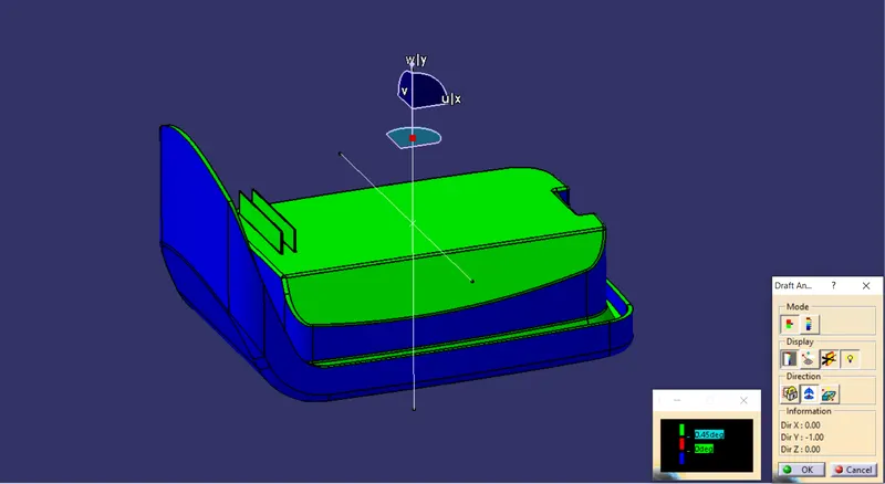
- Click the Draft Analysis tool and use the compass to define the draft direction as the main tooling Axis.
- Once placed correctly, lock the draft direction.
- Now, since the minimum draft angle for ribs is 0.5 deg per side, define the value as 0.45 deg as per tolerance and select the component
- The Draft Analysis is completed
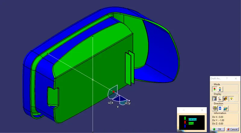
Isometric View
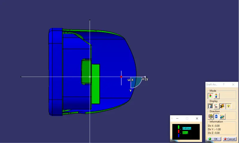
Front View
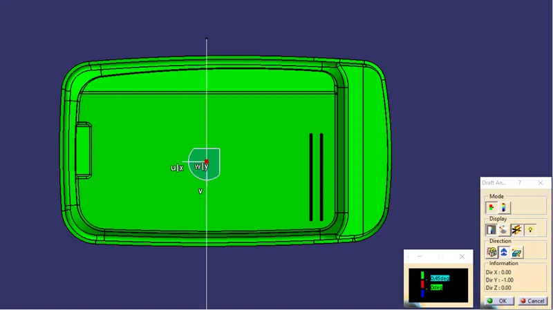
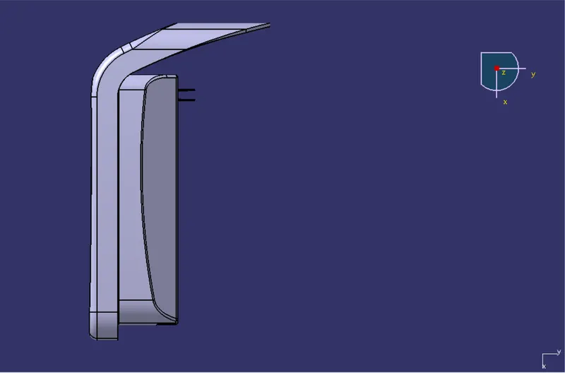
Side View
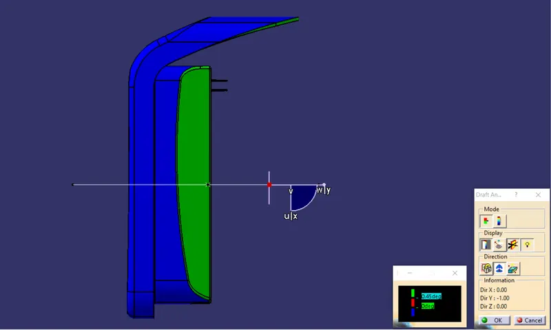
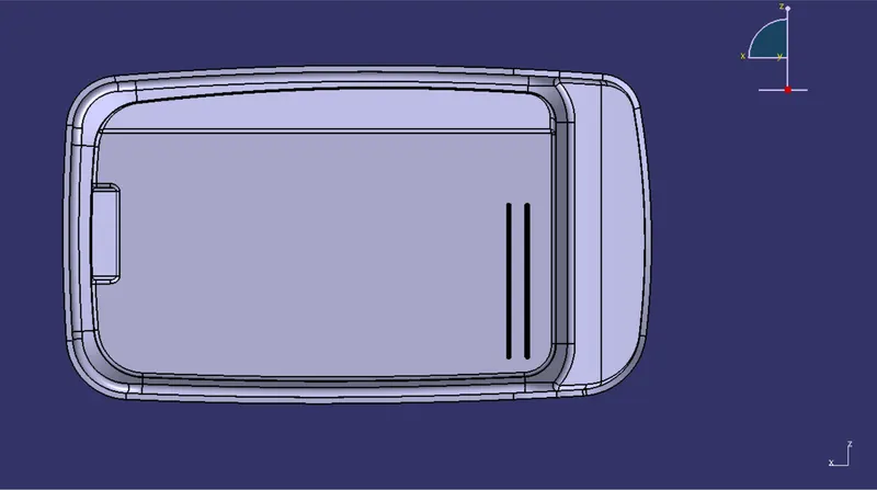
Top View
Results/ Conclusion of the Draft Analysis: By referring to the colour scale, the minimum draft angle of 0.45 deg is achieved and the component can be manufactured. The running point analysis tool can be used to find the value of draft angle at any point.
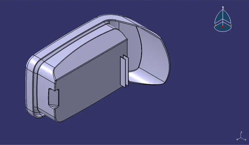
Isometric View
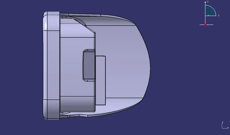
Front View
Side View
Top View