Week 8 - Challenge 1 - Draft Analysis on a Fan Cover
For successfully creating a component that is moldable or in other words that can be manufactured, Draft Analysis of the component should be carried out.
- What is a Draft?
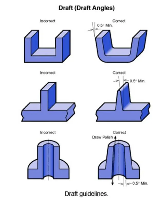
Essentially, draft angles for injection molding are a design consideration that makes it much easier for a part to release cleanly from a mold. A draft angle is calculated as a degree measurement from the vertical axis of a mold, and it helps account for thermoplastic shrinkage, a practical reality of the injection molding process for most materials.
By accounting for thermoplastic shrinkage during the cooling process, draft angles greatly reduce friction between the finished, cooled part and the side of the mold. Not only does this create a much easier release process, it offers several other benefits, depending on the design of the part:
- Reduces the chance of damage to the part due to friction during release
- Reduces wear and tear and chances of damage to the mold
- Ensures a uniform, smooth, unscratched finish when required
- Ensures the integrity and uniformity of other surface finishes and textures
- Reduces overall cooling time by lessening or eliminating the need for unconventional ejection setups
- Most, if not all, of these benefits offer either direct or indirect overall production cost reductions
Steps for creating the Tooling Axis:
- The first and foremost step for conducting the Draft Analysis is to create the Tooling Axis. The Tooling Axis is the direction in which the mold opens and closes.
- To create the Tooling Axis, first insert a point in the center and then create the Dummy Tooling Axis by inserting a line along the Z direction.
- Insert an Axis system at that point which is not defined as current.
- Now, the Tooling Axis Clearance is checked in the X and Y directions.
- Visually determine the sides/edges which might not clear the Tooling Axis. Then, create an intersection by giving the ZX plane and the fan cover as the inputs. Create two point-point lines along those edges. Finally, create a bisecting line by giving the two lines and the point as the input. This creates the Tooling Axis Clearance in X direction.
- Repeat the same procedure for the Y direction, starting by selecting the YZ plane.
- Once the Tooling Axis Clearances in X and Y direction are created, the final step is to create the main Tooling Axis. For this, insert a bisecting line by giving the Tooling Axis Clearances in X and Y direction and the point as inputs.
- Once the main Tooling Axis is created, publish the Class A surface and the Tooling Axis.
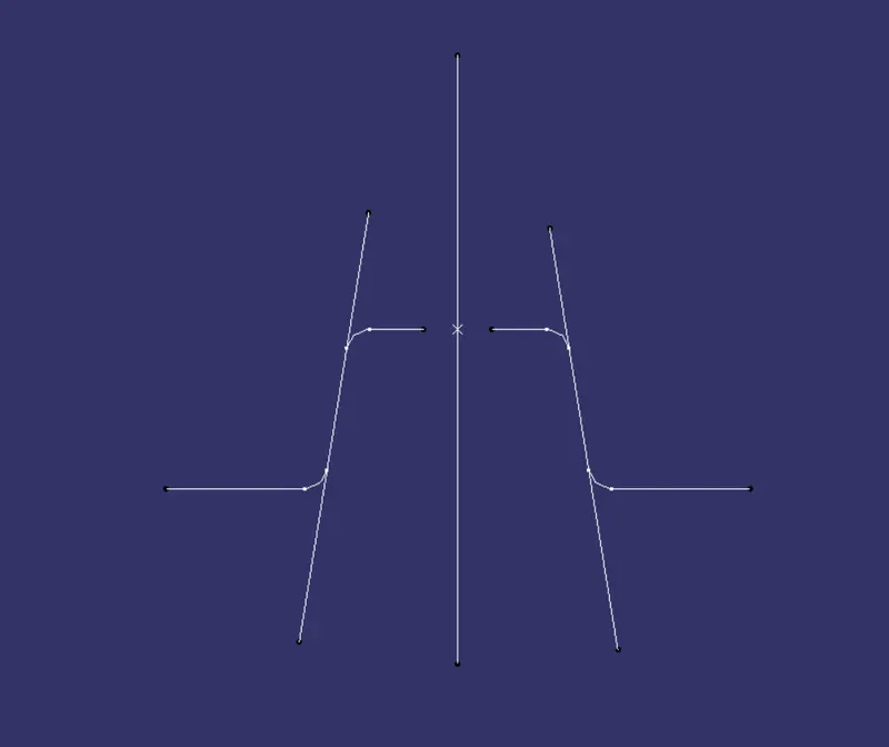
Fig: Tooling Axis X direction
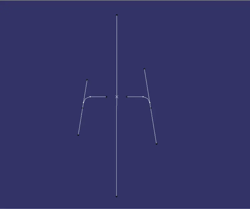
Fig: Tooling Axis Y direction
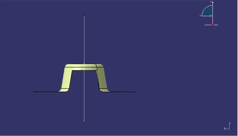
Fig: Main Tooling Axis
Steps for Draft Analysis:
- Go to Views and Customize View Parameters. Change to material.
- Click the Draft Analysis tool and use the compass to define the draft direction as the main tooling Axis.
- Once placed correctly, lock the draft direction.
- Now, since the minimum draft angle for plastic components is 3 deg, define the value as 3 deg and select the fan cover.
- The Draft Analysis is completed
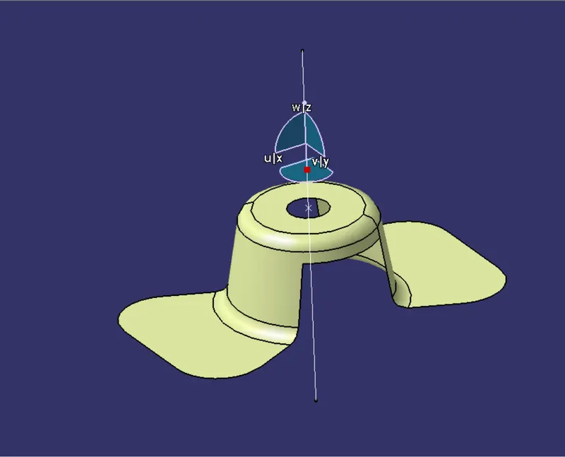
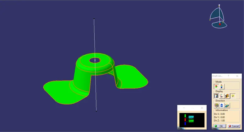
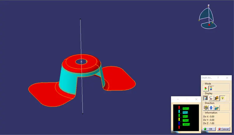
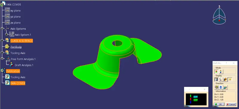
Isometric View
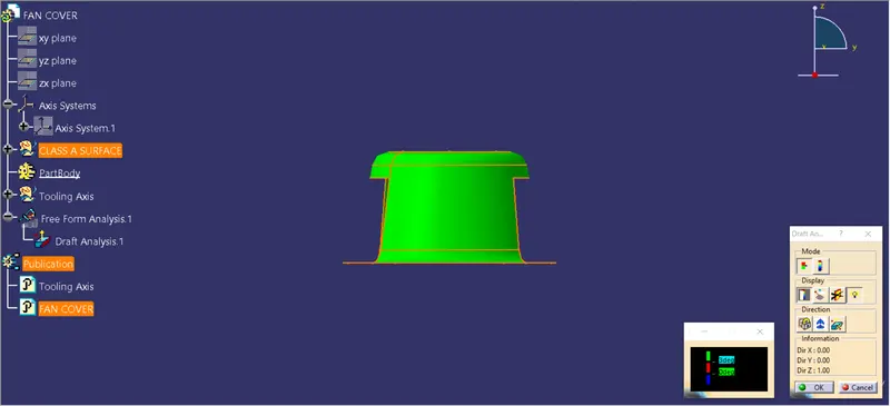
Front View
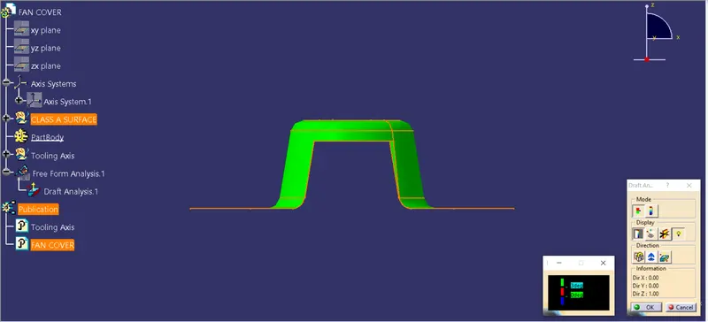
Side view
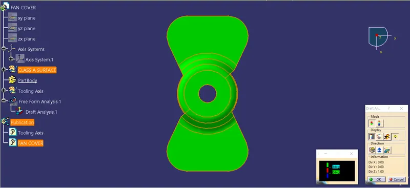
Top View
Results/ Conclusion of the Draft Analysis: By referring to the colour scale, the minimum draft angle of 3 deg is achieved and the component can be manufactured. The running point analysis tool can be used to find the value of draft angle at any point. If under any circumstances, the draft angle is found to be less than 3 deg, then appropriate changes should be done in defining the correct Tool Axis so that the draft angle is achieved and the component is manufactured.