Fender Design Challenge
FR- FENDER DESIGN
Objective: To Design and Develop the Front Fender of a car using NX 12.0.
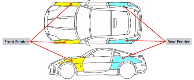
Introduction: Fender is the US English term for the part of an automobile (vehicle body) that frames a wheel well (the fender underside). Its primary purpose is to prevent sand, mud, rocks, liquids, and other road spray from being thrown into the air by the rotating tire. When vehicle is moving, tires pick up stones and gravels and hurl them in all directions. Fenders are basically present to prevent any injuries to pedestrians and contain the motion of these particles.
Fenders are typically rigid and can be damaged by contact with the road surface. Sticky materials, such as mud, may adhere to the smooth outer tire surface, while smooth loose objects, such as stones, can become temporarily embedded in the tread grooves as the tire rolls over the ground. These materials can be ejected from the surface of the tire at high velocity as the tire imparts kinetic energy to the attached objects. For a vehicle moving forward, the top of the tire is rotating upward and forward, and can throw objects into the air at other vehicles or pedestrians in front of the vehicle.
Most passenger automobiles have four fenders, one over each wheel. For vehicles with a narrow car body that exposes the tire, the fender is an exposed curve over the top of the tire. For wide body vehicles that cover the tire, the fender forms the wheel well surrounding the tire, and is not directly visible from above the car body.
Wheel wells tend to be much larger than the diameter of the tire, because they do not move with the tire suspension and consequently must be large enough to allow the full range of tire motion on the suspension without touching the interior of the wheel well. More elaborate designs include fender skirts for enclosing the outside edge of the wheel well, and stylized pontoon fenders for exposed fenders.
The common materials that are used for producing fenders are steel (sheet metal), Aluminum and Fiberglass.
Theory:
- Types of Fender:
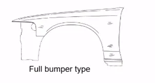
- Full Bumper Type
The full bumper type fender was used in old cars. This type of fender covers the full area until the front lighting. The major disadvantage of full bumper type fender is that it utilizes a lot of sheet metal material which is unnecessary and adds on the overall weight of the vehicle which reduces the performance. The maintenance also is relatively more due to more surface. Hence, these type of fenders are no longer in use.
- Half Bumper Type
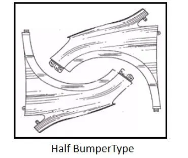
The half bumper type fender is used in modern cars since it uses less material as compared to the full bumper type. Thus, for the same sheet metal which can produce one full bumper type fender; can produce two half bumper type fenders. This also reduces the weight of the vehicle which improves the performance. The productivity increases by reducing the size of the blank. The maintenance is also relatively low compared to full bumper type.
- Fender skirts
Fender skirts are pieces of bodywork on the fender that cover the upper portions of the rear tires of an automobile. Fender skirts are implemented for both aesthetic and aerodynamic reasons. Rather than air flowing into and being trapped in the rear wheel well, it flows smoothly over the bodywork. They are generally detachable to allow for tire changes.
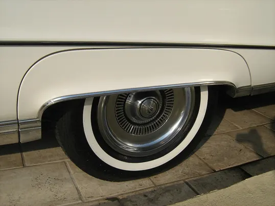
Figure 1: Fender Skirt
2. Design Requirements for Fender:
There are 5 mounting points in a fender. They are,
- Body
- A Pillar
- Sill
- Cowl
- Drip
The fender is mounted using fasteners and weldments.
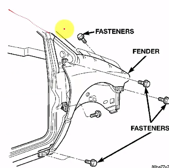
Figure 2: Fender Mounting Points
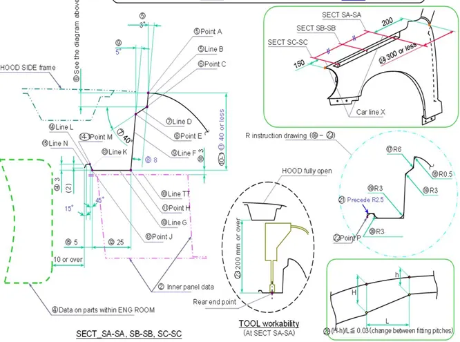
The Drip Area is of utmost importance. It is the region which connects the Fender to the Engine compartment. There are certain design guidelines which must be followed while designing the drip area. The same has been implemented in this project.
- Defects due to compression stamping such as camber, etc. occur. Thus, a touch difference is provided in flange depth when flange length exceeds 800.
- Hood side Drip depth must be 40mm or less as maximum productivity is achieved at the depth of 40mm. If depth exceeds 40mm, rigidity bead is to be provided. Also, forming is not feasible if depth exceeds 60mm due to wrinkling and spring back.
- When the Drip surface is stamped, 3 deg must be secured for spring back. Angle can be increased in order to make expected modification possible.
- Welding surface of Drip area with Bracket should be flat
3. Wheel Arch Regulations:
The wheel arch is the semicircular part positioned above the wheel of a vehicle. The design of wheel arch will be different based on countries and the main goal in designing of fender wheel arch should satisfy the regulation and standards as per the countries.
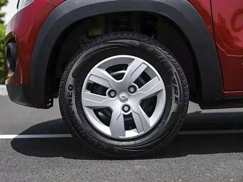
Figure 3: Wheel Arch
JAPAN REGULATIONS
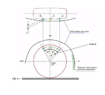
- The clearance L is more than 5mm should be followed in Japan regulation and standard.
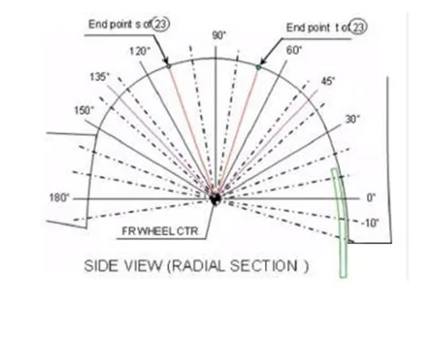
- Take an angle of 30 deg, 50 deg, and 90 deg from the center of the wheel and create vertical.
- Line B, A and C as shown below. L value has been measured between point of B, A, C and edge boundary of fender wheel arch.
EUROPEAN REGULATION STANDARD
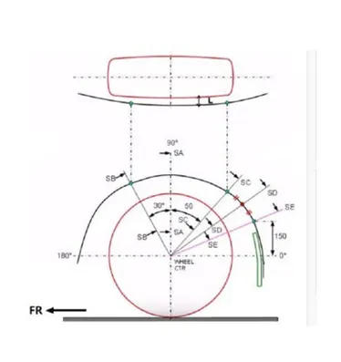
- The clearance L will be more than 10mm at the section of SB, SA, SC, SD, SE
- The section SA will be 90 degrees from the center of the wheel
- The section SB will be 30 degrees from the line SA
- The section SC will be 50 degrees from the line SA
- The section SE will be 150mm from the horizontal from the point of center
- The section SD will be the distance between SC and SE
US REGULATION STANDARD
- The section that we are going to measure L will be divided from -10 degree to 190 degree from the center of wheel like shown in fig.
- The clearance L is more than 5mm should be followed in US regulation and standard
Design in NX 12.0
Input:
Drip Area Master Section:
Fender Skin:
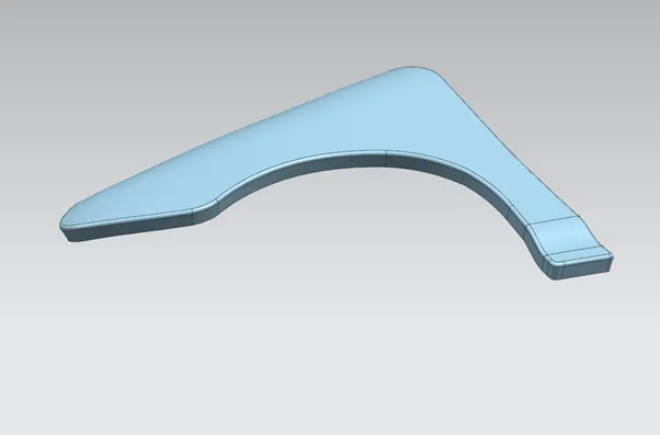
Designed Fender:
Drip Area:
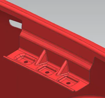
Baffle mounting region:
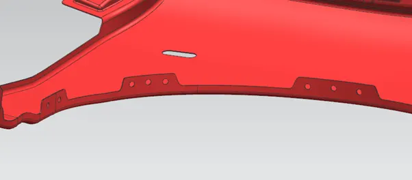
Sill Area:
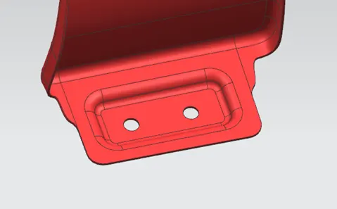
Bumper Area:
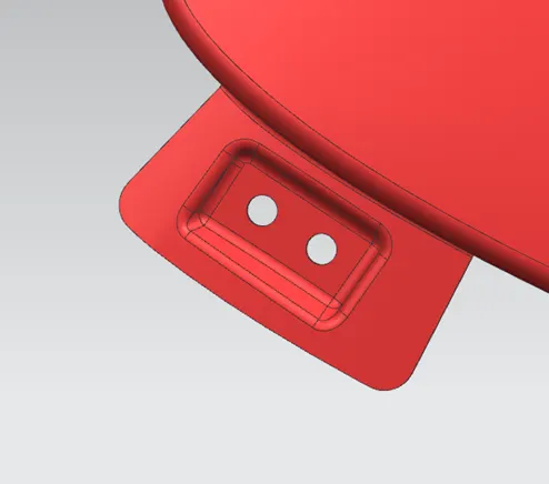
A Pillar region:
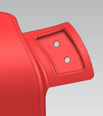
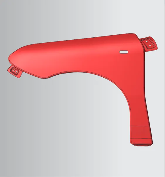
Fender Front View:
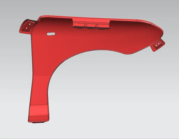
Fender Back View:
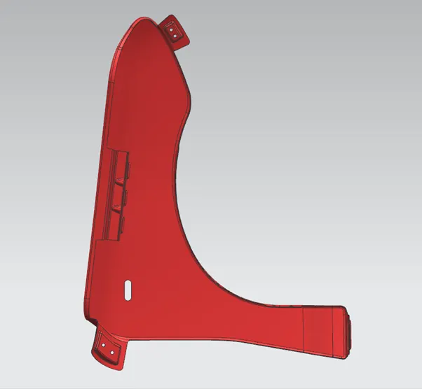
Fender Side View:
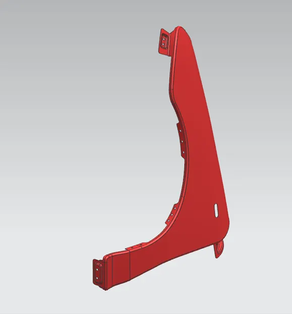
Fender Trimetric View:
The following commands have been used for designing the Fender:
- Offset in face
- Curve on Surface
- Trim Sheet
- Law Extension
- Datum Plane
- Intersection Curves
- Dart
- Face Blend
- Sew
- Edge Blend
- Bridge Curve
- Projected Curve
- Emboss
- Extend Sheet
- Composite Curve
- Trim Curve
- Through Curves
- Trim and Extend
- Thicken
Conclusion: Thus, the Front Fender has been designed in NX 12.0. The Curve and Surface Workbenches have been extensively used for the modeling of fender.