Design of backdoor
BACK DOOR DESIGN
Objective: To Design the Back Door/Tail Gate of a car, with its components – Outer Panel, Inner Panel and Reinforcements.
Introduction: The Backdoor of a car is a hinged component that allows access to the luggage area of the vehicle. The trunk or boot of a car is the vehicle’s main storage or cargo compartment, often a hatch at the rear of the vehicle. It is also called a tailgate. Just like the Hood of the car, the Backdoor is also operated by gas stay mechanism. The gas stay lift can be powered by an electric motor.
The door or opening of a cargo area may be hinged at the top, side, or bottom. If the door is hinged at the bottom, it is called a tailgate. They are used on station wagons and pickup trucks, as well as on some sport utility vehicles (SUV). Two-way station wagon tailgates may be hinged at the side and the bottom so they can be opened sideways like a regular door, or drop downwards as load platform extenders. They are designed with special handle(s) for opening in the selected direction on special hinges.
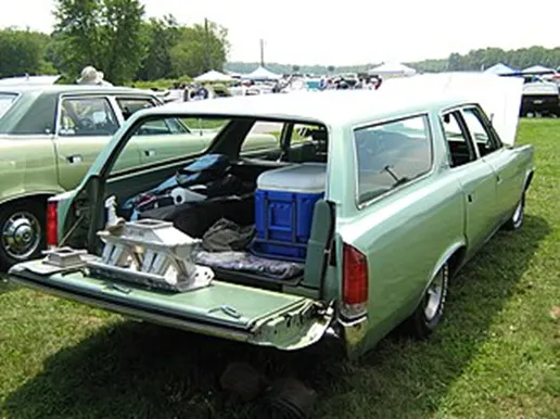
Figure 1: Two-way station wagon tailgate
If the door is hinged at the top, it is termed a hatch, and is used on a hatchback.

Figure 2: Hatchback
Theory:
- Material Selection for Backdoor :
Differences between Aluminum and Steel parts
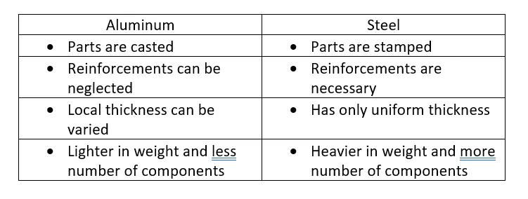
Since, Aluminum is a costly material, Steel may still be preferred despite of all the advantages that Aluminum has over Steel.
2. Backdoor Joining processes :
- Hemming:
Hemming is a forming operation in which the edges of the sheet are folded or folded over another part in order to achieve a tight fit. Normally hemming operations are used to connect parts together, to improve the appearance of a part and to reinforce part edges.
In car part production, hemming is used in assembly as a secondary operation after deep drawing, trimming and flanging operations to join two sheet metal parts (outer and inner) together. Typical parts for this type of assembly are hoods, doors, trunk lids and fenders.
The accuracy of the hemming operation is very important since it affects the appearance of the surface and surface quality. Material deformations, which occur during the hemming process, can lead to dimensional variations and other defects in parts. Typical hemming defects are splits or wrinkles in the flange, material overlaps in the corner areas or material roll-in. This is why it is important to use simulation tools in order to, on the one hand, better understand the hemming process and, on the other hand, significantly reduce the number of “trial and error” loops during try out und production.
There are two types of hemming operations: Conventional die hemming and Roll hemming
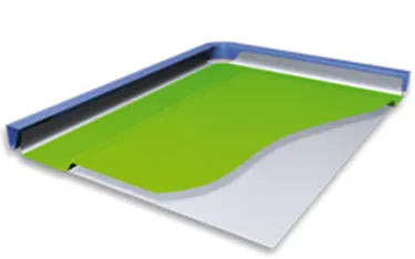
Conventional die hemming
Conventional die hemming is suitable for mass production. In die hemming, the flange is folded over the entire length with a hemming tool. Normally the actual hemming is a result of a forming operation in which the flange is formed with a hemming tool after the drawing and trimming operations have been completed. The formed flange is then hemmed in several process steps. These steps include, for example, the pre-hemming and final hemming depending on the respective opening angle of the flange. Production plants for conventional die hemming are very expensive, but the cycle times are very low.
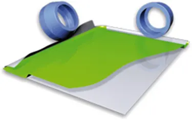
Roll hemming
Roll hemming is carried out incrementally with a hemming roller. An industrial robot guides the hemming roller and forms the flange. Roll hemming operation can also be divided into several pre-hemming and final hemming process steps. Roll hemming is very flexible to use and tool costs are significantly lower as compared to those of conventional die hemming. However, the cycle times are much higher since the hemming is realized using a hemming roller which follows a defined path.
- Mastic Joint Sealant:
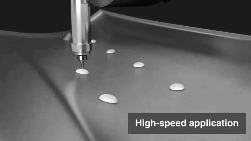
Mastic Sealants are used for gluing the Inner panel of Backdoor to the outer panel. In addition to the hemming process, mastic sealants improve the strength locally within a range of 80mm dia. It also provides reinforcement and is a popular choice when one surface is to be adhered to another in a durable bond.
- Spot Welding
Spot welding (also known as resistance spot welding) is a resistance welding process. This welding process is used primarily for welding two or more metal sheets together by applying pressure and heat from an electric current to the weld area.
It works by contacting copper alloy electrodes to the sheet surfaces, whereby pressure and electric current are applied and heat is generated by the passage of current through resistive materials such as low carbon steels.
A form of resistance welding, spot welding is one of the oldest welding processes whereby two or more sheets of metal are welded together without the use of any filler material.
The process involves applying pressure and heat to the weld area using shaped alloy copper electrodes which convey an electrical current through the weld pieces. The material melts, fusing the parts together at which point the current is turned off, pressure from the electrodes is maintained and the molten “nugget” solidifies to form the joint.
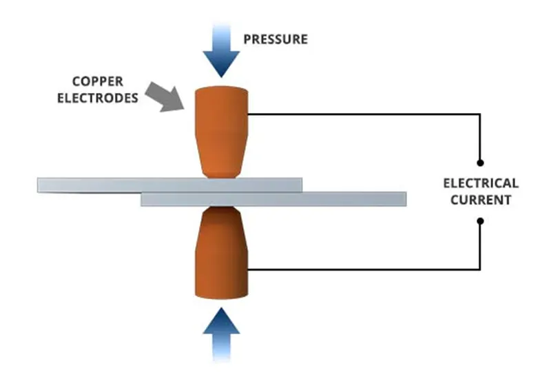
The welding heat is generated by the electric current, which is transferred to the workpiece through copper alloy electrodes. Copper is used for the electrodes as it has a high thermal conductivity and low electrical resistance compared to most other metals, ensuring that the heat is generated preferentially in the work pieces rather than the electrodes.
Spot welding has applications in a number of industries, including automotive, aerospace, rail, white goods, metal furniture, electronics, medical building and construction.
Given the ease with which spot welding can be automated when combined with robots and manipulation systems, it is the most common joining process in high volume manufacturing lines and has in particular been the main joining process in the construction of steel cars for over 100 years.

Design on NX 12.0
Inputs:
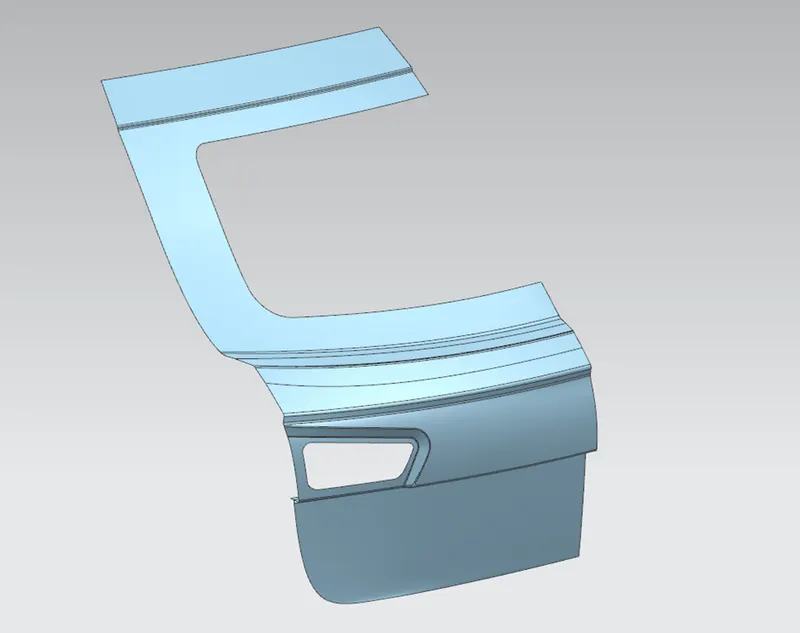
The Back Door Outer Panel consists of Upper and Lower halves whose styling surfaces are given as inputs.
Designed Back Door:
1. Outer Panel Upper
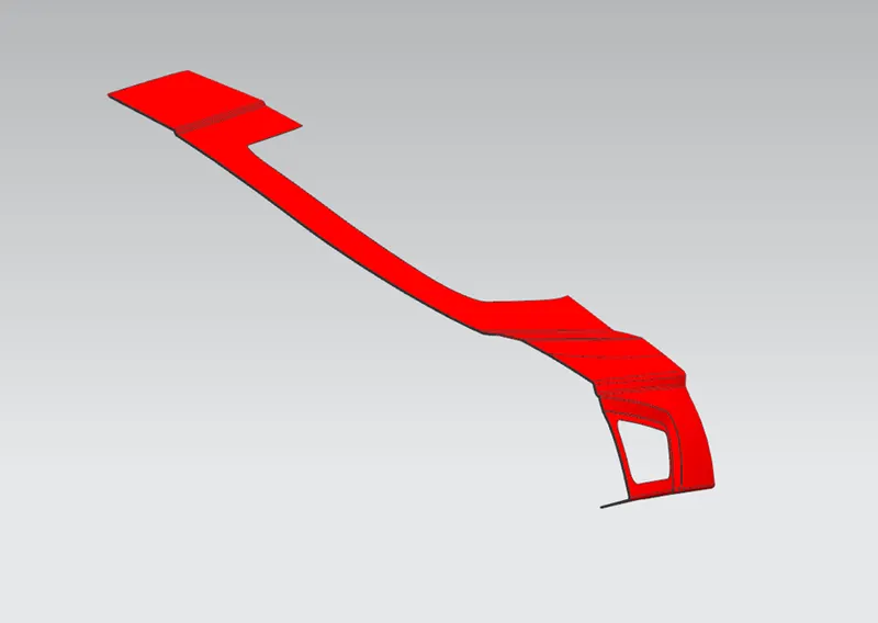
Figure 3: Side View
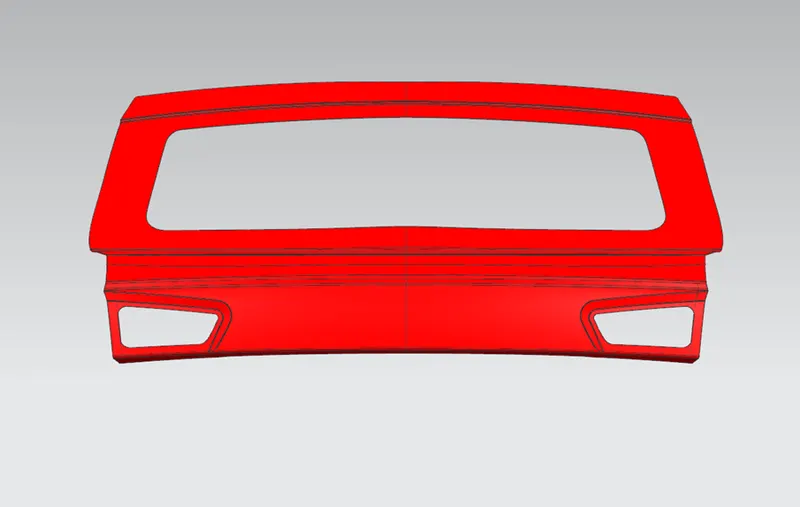
Figure 4: Front View
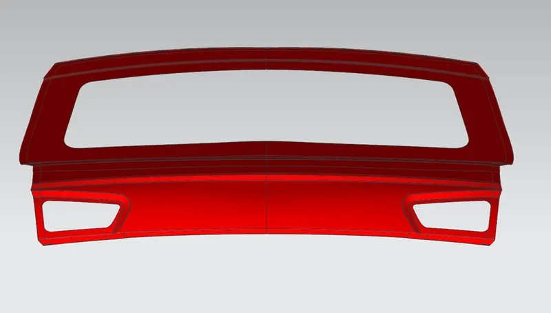
Figure 5: Back View
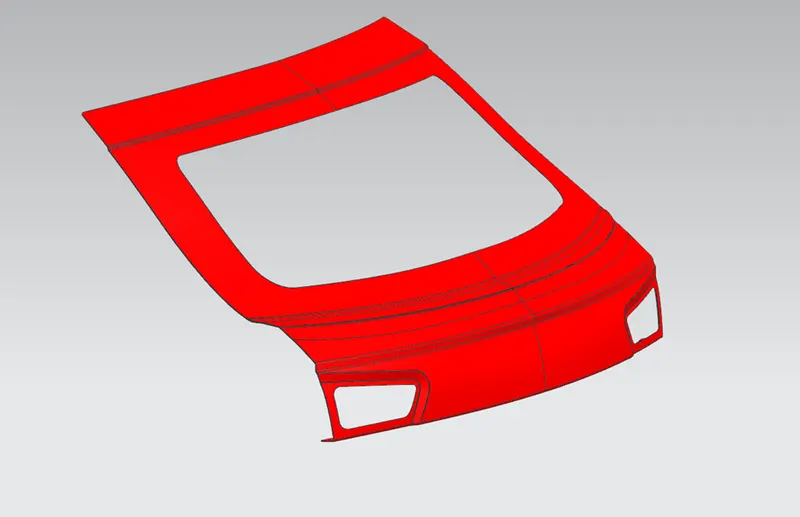
Figure 6: Isometric View
2. Outer Panel Lower
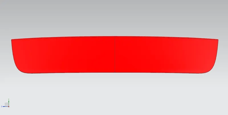
Figure 7: Front View
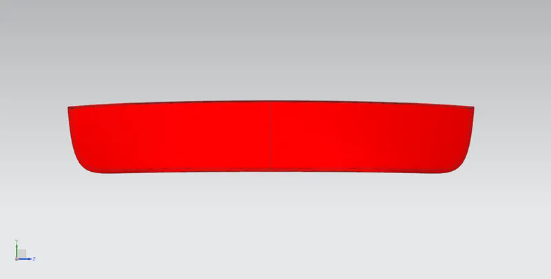
Figure 8: Back View
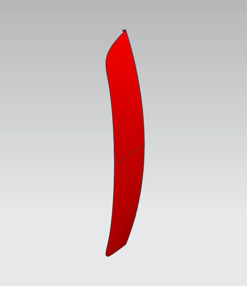
Figure 9: Isometric View
3. Outer Panel
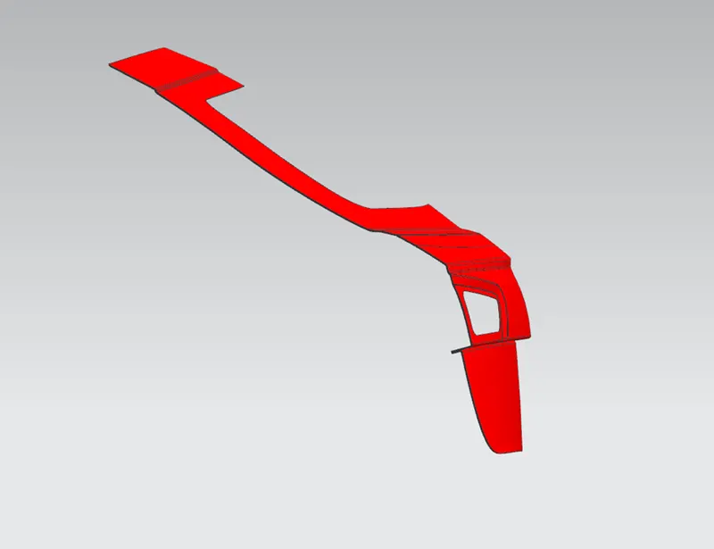
Figure 10: Side View
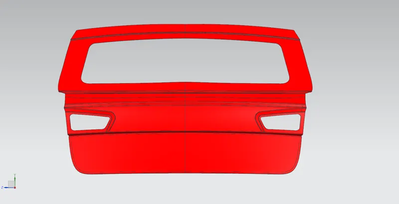
Figure 11: Front View
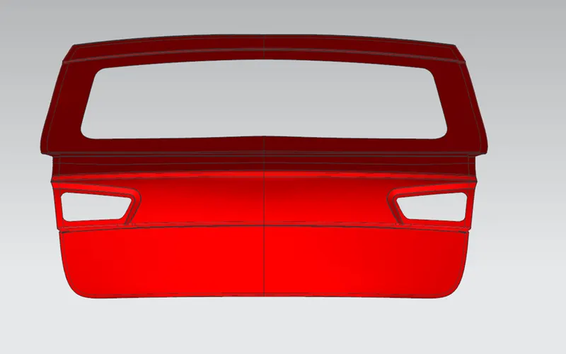
Figure 12: Back View
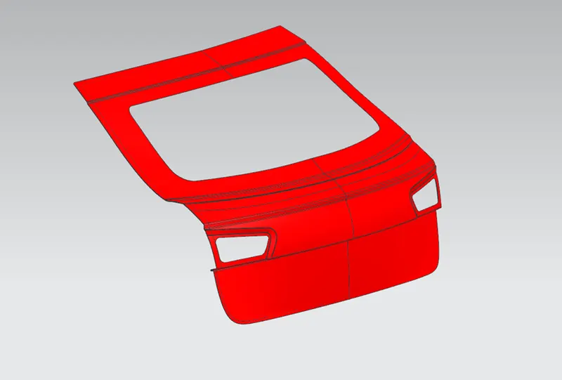
Figure 13: Isometric View
4. Inner Panel
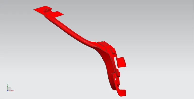
Figure 14: Side View
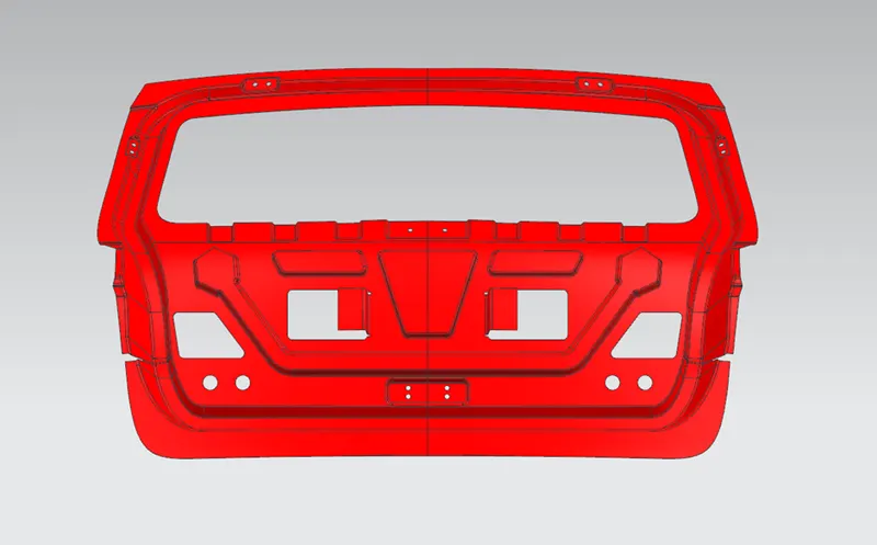
Figure 15: Front View
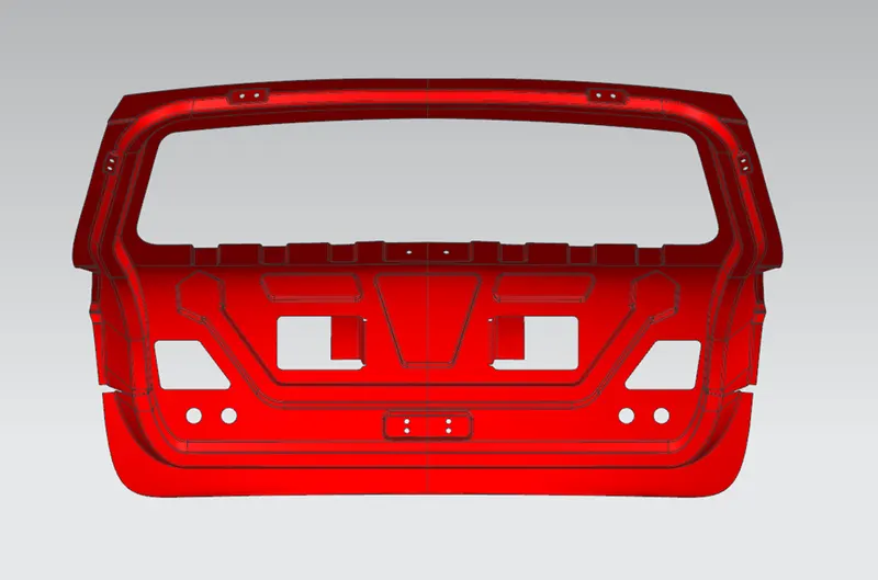
Figure 16: Back View
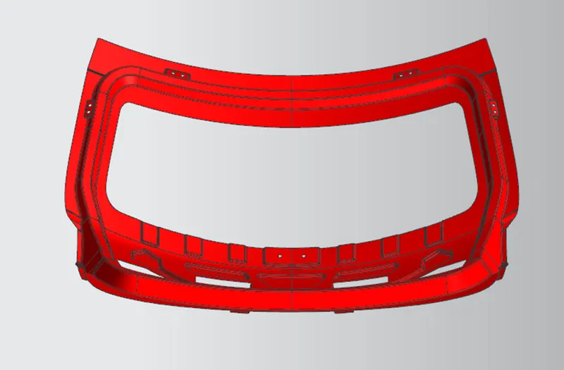
Figure 17: Bottom View
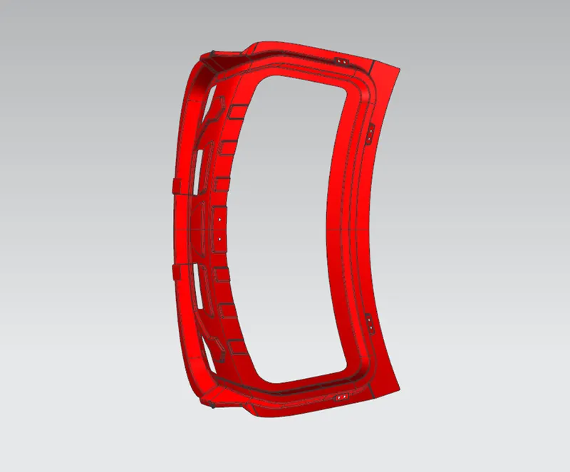
Figure 18: Top View
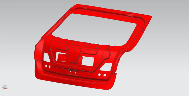
Figure 19: Isometric View
5. Reinforcements: Reinforcements are provided to impart localised strength.
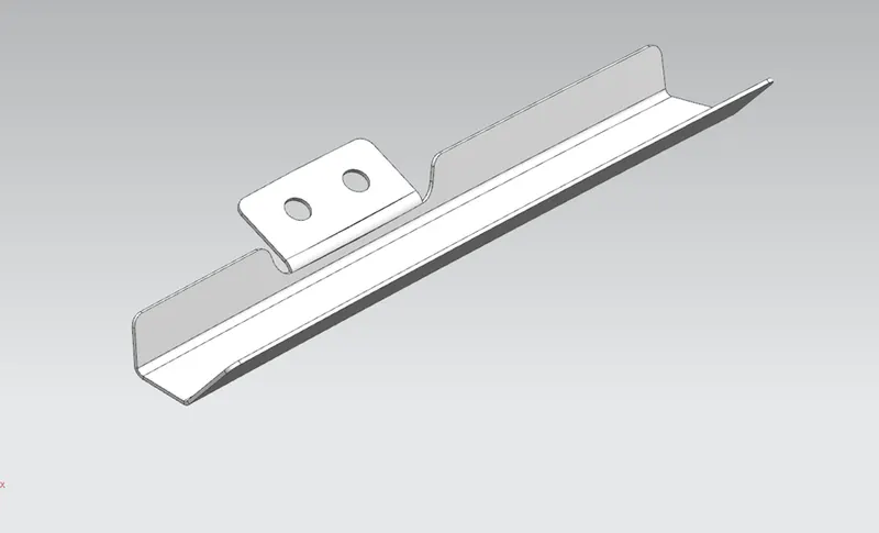
Figure 20: Hinge Reinforcement
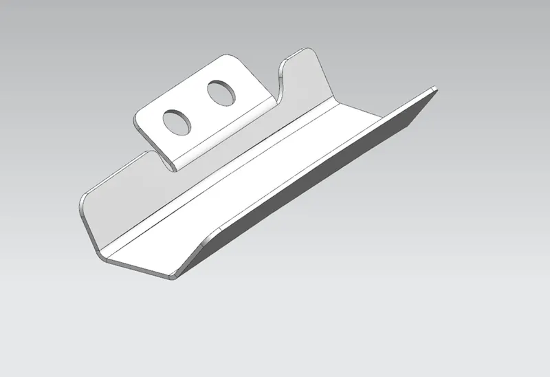
Figure 21: Gas Stay Reinforcement
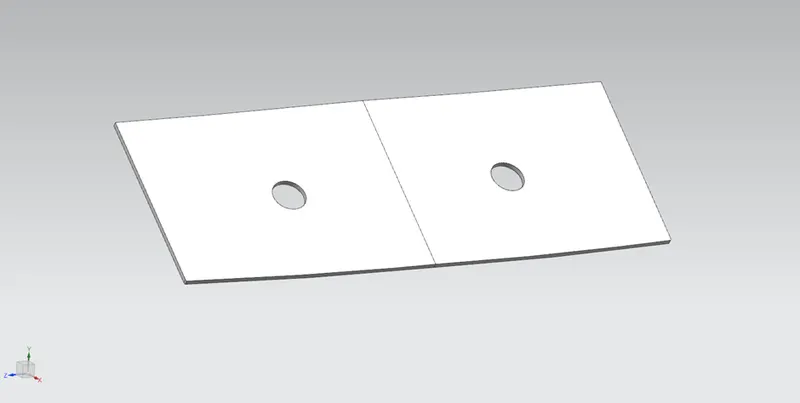
Figure 22: Wiper Motor Reinforcement
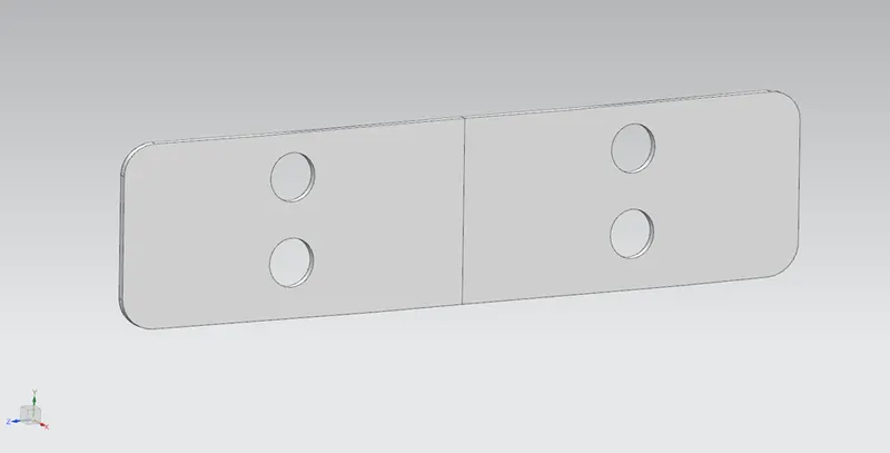
Figure 23: Latch Reinforcement
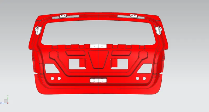
Figure 24: Inner Panel with Reinforcements
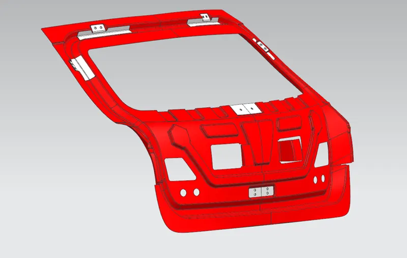
Figure 25: Isometric View
Back Door Assembly:
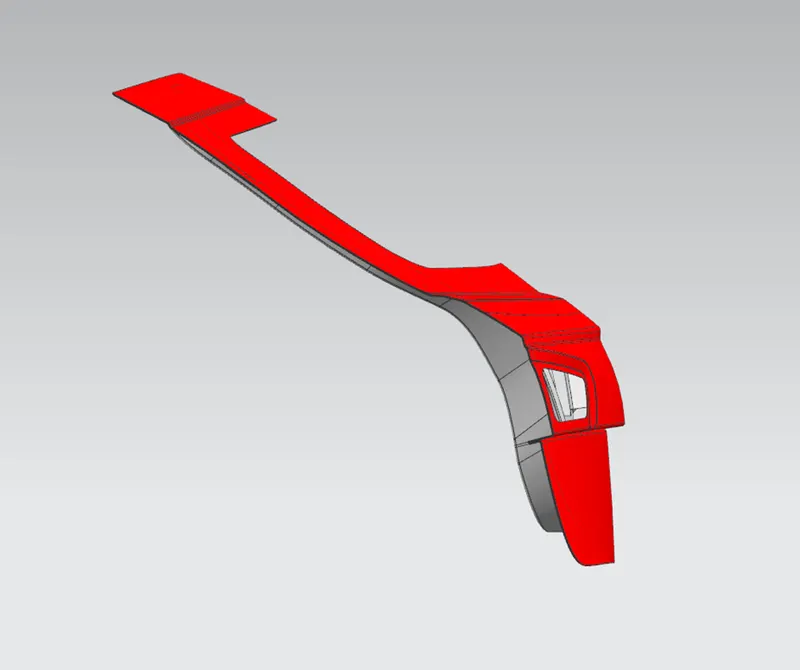
Figure 26: Side View
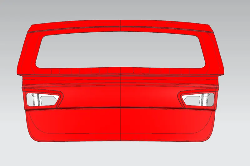
Figure 27: Front View
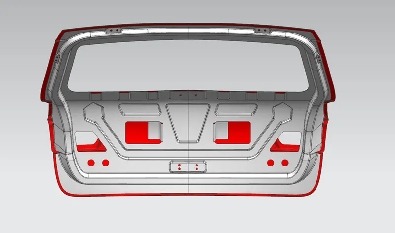
Figure 28: Back View
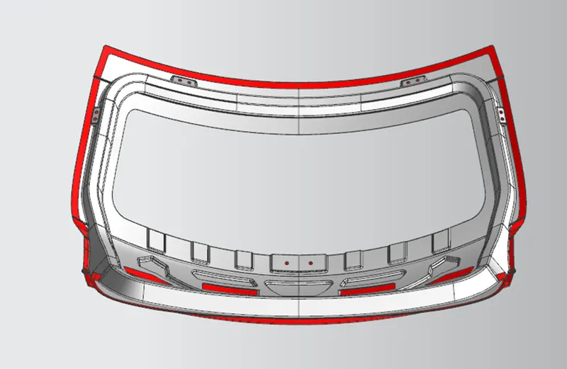
Figure 29: Top View
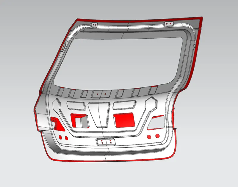
Figure 30: Isometric View
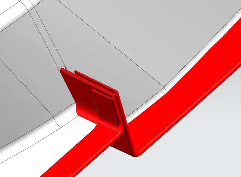
Figure 31: Hemming
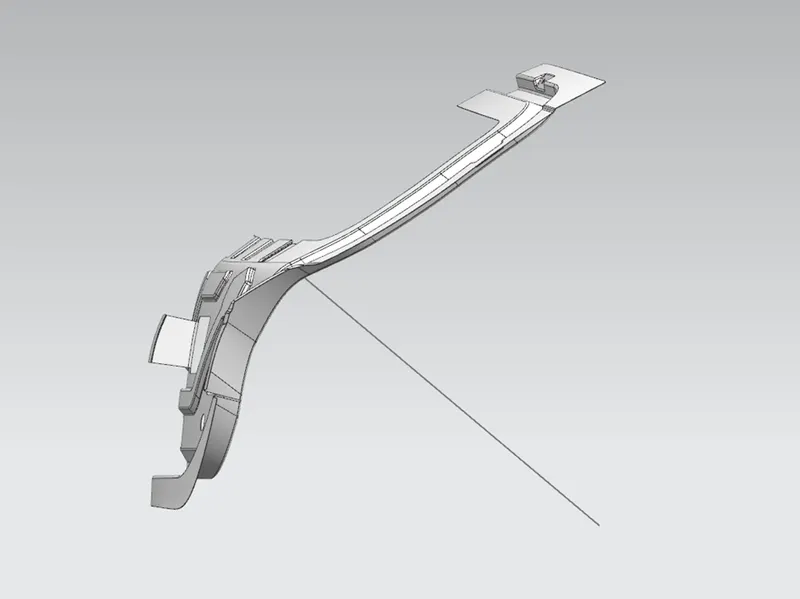
Figure 32: Tooling direction
Draft Analysis of Inner Panel:
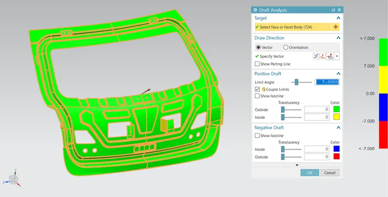
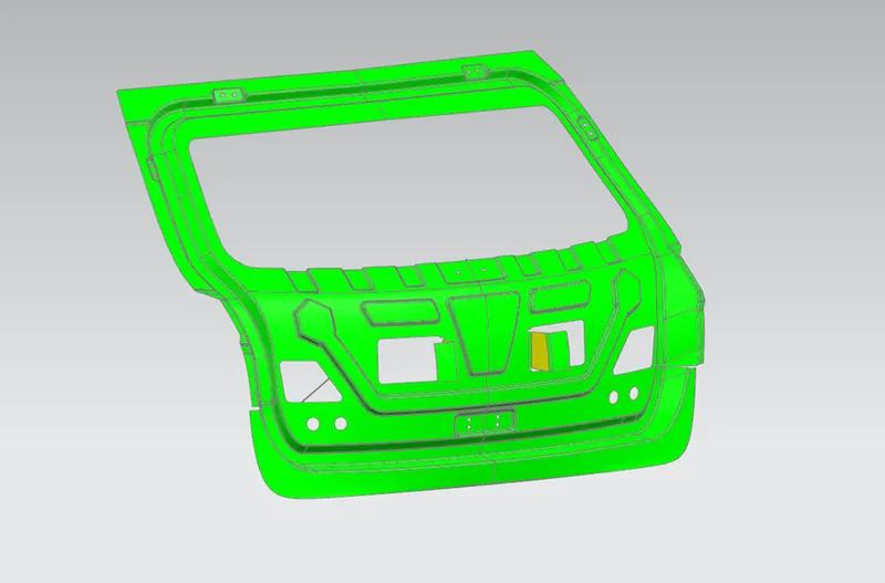
Following Tools/commands are used to create the Backdoor:
- Extract Geometry
- Bridge Curve
- Through Curve Mesh
- Sew
- Trim Sheet
- Offset Surface
- Offset in face
- Swept
- Datum Plane
- Intersection Curves
- Extend Sheet
- Mirror Geometry
- Thicken
- Untrim
- Projected Curve
- Law Extension
- Face Blend
- Edge Blend
- Blend Corner
- Trim and Extend
- Studio Surface
- Curve on Surface
- Emboss
- Wave Geometry Linker
- Mirror Assembly
Conclusion: Thus, the Back Door is designed in NX 12.0. The Curve, Surface, Assemblies and Analysis Workbenches of NX are used in the project.