Week 11 - Final project
PROJECT REPORT
Title: Development of Door Trim Panel – Automotive Plastic Component Design
Aim/Objective: To develop the Interior Door Trim Panel Assembly with its components Map Pocket, Map Pocket with Bottle Holder, Lower Substrate and Door Arm Rest using the Class A Surface and Master Sections as Inputs. The Design and subsequent Development of Assembly is done using CATIA V5 software wherein the Top-Down approach is followed and the concepts and design rules of Plastic Product Design are implemented.
The components in consideration are Automotive Plastic Components and have to be developed in accordance to the DFMA (Design for Manufacturing and Assembly) rules used in an Automotive Industry. The DFMA are a set of rules that define the feasibility of the designed component to be manufactured by Injection Molding which is a widely used Manufacturing technique for Plastic products.
Introduction:
Automotive Door is a vital component in a vehicle as it is the entry and exit point of the vehicle. The Door Trim is an interior component attached to the inner side of the door. This product does more than merely improve the appearance of the vehicle interior. Rather, it is a vital module component that creates a more comfortable interior by providing a variety of accouterments and functions.
Door Panels are also considered as one of the crucial components in vehicles as they provide reliable side protection, ergonomic comfort and convenience. They are usually made of plastic material.
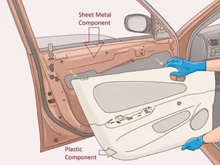
Figure 1: Door Trim Panel
Theory:
1. Draft:
Essentially, draft angles for injection moulding are a design consideration that makes it much easier for a part to release cleanly from a mould. A draft angle is calculated as a degree measurement from the vertical axis of a mould, and it helps account for thermoplastic shrinkage, a practical reality of the injection moulding process for most materials.
By accounting for thermoplastic shrinkage during the cooling process, draft angles greatly reduce friction between the finished, cooled part and the side of the mould. Not only does this create a much easier release process, it offers several other benefits, depending on the design of the part:
- Reduces the chance of damage to the part due to friction during release
- Reduces wear and tear and chances of damage to the mould
- Ensures a uniform, smooth, unscratched finish when required
- Ensures the integrity and uniformity of other surface finishes and textures
- Reduces overall cooling time by lessening or eliminating the need for unconventional ejection setups
- Most, if not all, of these benefits offer either direct or indirect overall production cost reductions
Guidelines for giving the draft angle:
- Most applications require a minimum draft angle of around 0.5deg to 1deg, however 3deg draft angles are widely accepted in the industry
- 7deg draft angles are given to textured surfaces like the Instrument Panels
- Minimum possible draft angles are given to screw bosses, ribs, heat stakes, locators due to their critical nature
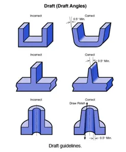
Figure 2: Draft Guidelines
2. Tooling Axis:
The Tooling Axis is the direction in which the mould opens and closes. Part Drafts are generally given along this axis.
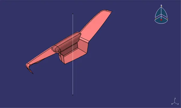
Figure 3: Tooling Axis
3. Side Core Axis:
Some features or walls are difficult to clear by the Main Tooling Axis itself. These features may be part of a sub feature which is important and cannot be ignored. For example, Ribs. These features need a different tooling axis for clearing the part in the mould. This tooling axis is called as the Side Core Axis. Adding a Side Core increases the manufacturing cost and hence it is only used when it is necessary.
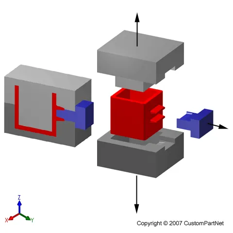
Figure 4: Side Core Axis
4. Lifter Axis:
The lifter is mainly used to form the internal undercuts of a moulded plastic part, and at the same time it also offers ejection function. In moulding, an undercut is an indentation or protrusion in a shape that will prevent its withdrawal from a one-piece mould.
Undercuts on moulded parts are features that prevent the part from being directly ejected from an injection moulding machine. They are categorized into internal and external undercuts, where external undercuts are on the exterior of the part and interior undercuts are on the inside of the part.
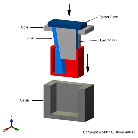
Figure 5: Lifter
5. Draft Analysis:
Draft Analysis is an Analysis Tool in CATIA that identifies the regions that deviates from the specified values of draft angles along a defined draft direction i.e., along the Main Tooling Axis or Side Tooling Axis. Draft Analysis is the first step performed after receiving the Class A Surface of the component. Draft Analysis should be cleared in order to make the given plastic component manufacturable since it is the factor which decides the perfect ejection of the component from the mould. Acceptable Draft Angles are given as input for Draft Analysis and the angles may vary from feature to feature. The colour coded output of the Draft Analysis then determines the regions where required draft angles have to be provided in order to make the part manufacturable. In some cases, if the given Class A is itself not provided with the suitable draft, then that is given as feedback to the Class A designer where upon the surface is reworked.
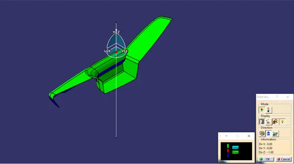
Figure 6: Draft Analysis
6. Class A Surface:
Class A Surface is prepared from the concept sketches. That means the surface of a component which is smooth (aesthetic) or visible side to human eye after the part is assembled. The Class A surfaces have continuous curvatures. This means that at each point of each surface along the common boundary has the same radius of curvature and therefore the boundaries have been blended. In automobile design applications, Class A Surfaces are created on all visible exterior surfaces (ex, body panels, bumpers, grill, lights, etc) and all visible surfaces of see-touch & feel parts in interior (ex, dashboard, seats, door pads, etc)
7. Class B Surface:
Class B Surfaces are secondary surfaces which are invisible to the eyes or often on the rear side of Class A Surfaces. These must be smooth and error free as well, but are not held to the standards that Class-A Surfaces are. These surfaces include the main Engineering features such as Ribs, Screw Bosses, Heat Stakes, Locators, Doghouses, etc. Hence, these features are also called as B-side features.
8. Class C Surface:
Class C Surface is the connecting surface between the Class A and Class B surfaces. In other words, it imparts the thickness to the component.
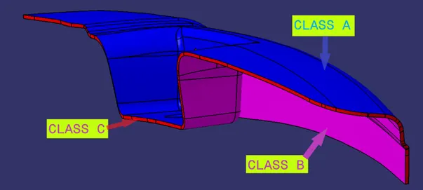
Figure 7: Illustration of Class A, B and C Surfaces
9. ABS and ABS blends are primarily used materials in Door Trim. ABS stands for Acrylonitrile Butadiene Styrene. The following properties of ABS facilitates their use in Automotive components:
- High rigidity
- Good impact resistance
- Good insulating properties
- Good weldability
- Good abrasion and strain resistance
- High dimensional stability (Mechanically strong and stable over time)
- High Surface brightness and excellent surface aspect
- Scratch Resistant
10. Design Rules for Plastic Components:
- The nominal wall thickness of an injection moulded plastic component is 3mm. However, the thickness of the component may slightly vary depending on its application. For example, for components such as Instrument Panels, Bumpers which requires strength, the values of thickness can be larger than 4mm. For smaller components such as Coin Holder, the thickness may be between 2-3mm.
- Deviation of 30% from the wall thickness is allowed with gradual increase or decrease to avoid any plastic defects while manufacturing. For ex, A component having wall thickness 3mm is allowed to have a minimum of 2.1mm and a maximum of 3.9mm wall thickness.
- The Plastic component should have a uniform wall thickness
- Ideal Draft Angle should be 3deg
11. B-Side Engineering Features:
Ribs:
Ribs provide a means to economical stiffness and strength in moulded parts without increasing the overall wall thickness. They also facilitate:
- Locating and arresting components of an assembly
- Providing alignment in mating parts
- Acting as stops or guides for mechanisms
Proper Rib Design involves the following considerations on Show Surfaces:
- Draft
- Thickness
- Height
- Spacing between two Ribs
- Thickness at top
- Optional fillet radius
Rib Thickness: Thick ribs often cause sink mark and in turn cosmetic problems on the opposite surface of the wall to which they are attached. The material, rib thickness, surface texture, colour, proximity to a gate, and a variety of processing conditions determine the severity of sink.
Highly glossy, critical surfaces may require thinner ribs. Thin-walled parts (<1.5mm) can often tolerate ribs that are thicker than the percentages in these guidelines. On parts with wall thicknesses that are 1mm or less, the rib thickness should be equal to the wall thickness.
Rib thickness also directly affects moldability. Very thin ribs can be difficult to fill. Because of flow hesitation, thin ribs near the gate can sometimes be more difficult to fill than those further away.
Flow entering the thin ribs hesitates and freezes while the thicker wall sections fill. Ribs usually project from the main wall in the mould-opening direction. To facilitate part ejection from the mould, ribs generally require at least one-half degree of draft per side. More than 1deg of draft per side can lead to excessive rib thickness reduction and filling problems in tall ribs.
Rib Size generally, taller ribs provide greater support. To avoid mould filling, venting and ejection problems, standard rules of thumb limit rib height to approximately 5* the rib-base thickness. Because of the required draft for ejection, the tops of tall ribs may become too thin to fill easily.
Additionally, very tall ribs are prone to buckling under load. In such conditions, consider designing two or more shorter, thinner ribs to provide the same support with improved moldability. Maintain enough space between ribs for adequate mould cooling, for short ribs allow at least two times the wall thickness.
Design Rules for Rib Design:
The Rib is designed keeping in mind the following guidelines:
- Rib thickness, w = 0.4*t where 't' is the wall thickness
- Minimum draft angle = 0.5deg per side
- Rib thickness at tip = 0.75mm
- Rib fillet radius = 0.25 maximum
- Rib height <= 5* nominal wall thickness
- Spacing between two ribs = max 3:1 ratio, preferred ratio = 2:1
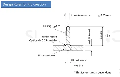
Figure 8: Rib Design
Screw Bosses:
Bosses find use in many part designs as points for attachment and assembly. The most common variety consists of cylindrical projections with holes designed to receive screws, threaded inserts or other types of fastening hardware. As a rule of thumb, the outside diameter of bosses should remain 2 to 2.4 times the outside diameter of the screw or insert.
Avoid Bosses that merge into sidewalls because they can form thick sections that lead to sink. Instead position the bosses away from the sidewall, and if needed use connecting ribs for support. Consider using open boss designs for bosses near a standing wall.
Normally, the boss hole should extend to the base wall level, even if the full depth is not needed for assembly. Shallower holes can leave thick sections, resulting in sink or voids. Deeper holes reduce the base wall thickness, leading to filling problems, knit lines, or surface blemishes. The goal is to maintain a uniform thickness in the attachment wall. Because of the required draft, tall bosses- those greater than five times their outside diameter- can create a filling problem at their top or a thick section at their base.
Design Rules for Screw Boss:
The Screw Boss is designed keeping in mind the following guidelines:
- Draft = 0.5deg inside and outside
- Thickness, w = 0.6*T where 'T' is the base wall thickness
- Height to Diameter Ratio = 3:1
- Optional radii = 0.25mm maximum
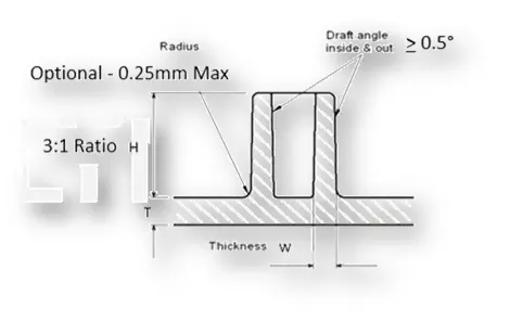
Figure 9: Screw Boss Design
Doghouses:
Dog House serves the following purposes:
- To avoid sink marks
- When screw boss is to be perpendicular to the Tooling Axis
- When the length of the screw boss is too much
The guidelines that are followed for Dog House design are as follows:
- Minimum draft for doghouses is 1.5 degrees
- Doghouse wall thickness at intersection of part wall (C) should be 40% or less than the main wall stock(T)
- Height of B should be between 3-6mm
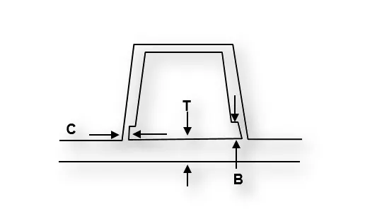
Figure 10: Doghouse Design
"C" is where the doghouse connects backside of surface
4 Way and 2 Way Locators:
- Locators are used to locate a component to arrest its degrees of freedom using the 3-2-1 principle.
- 3-2-1 principle: In the automotive tooling industry, Ideally, 3-2-1 principle is used to locate the job. Any part which has to be fixed during welding or during machining process has to be fixed. Every object is having 12 degrees of freedom:
- Translational movement along X-axis
- Translational movement along Y-axis
- Translational movement along Z-axis
- Rotational movement along X-axis
- Rotational movement along Y-axis
- Rotational movement along Z-axis
- The 4 Way and 2 Way Locators are used to arrest the Translational and Rotational motion along all directions except the one direction in which the component is going to be welded/fixed to other component.
- Both these Locators follow the same Rib Design Guidelines
- In addition, the Locators are provided with a suitable entry chamfer and the height of these Locators should be greater than the height of the heat stakes.
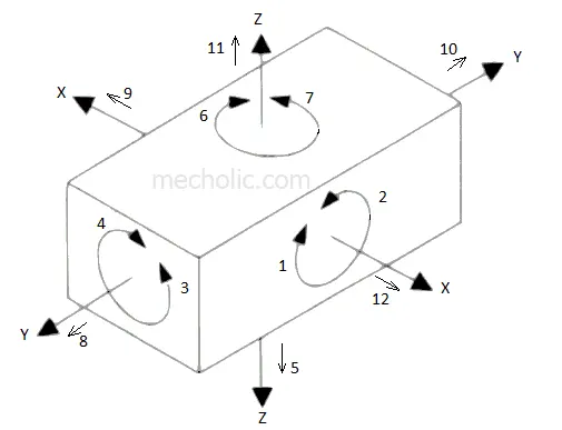
Figure 11: Degrees of Freedom
Heat Stakes:
In manufacturing products with thermoplastic components, it is often necessary to join a thermoplastic to a part of dissimilar material, whether it be metal, a dissimilar plastic, or other material
Thermal Staking is an assembly method that uses the controlled melting and reforming of a plastic stud or boss to capture or lock another plastic or metal component of an assembly in place. The plastic stud protrudes through a hole in the component to be locked in place. The heated thermal tip contacts the top of the stud, which melts and fills the volume of the tip cavity to produce a head, locking the component in place.
The progressive melting of plastic under continuous pressure forms the head. When staking, the right combination of heat and pressure for the application is critical.
Advantages:
- Simplification of machinery
- Reduced cost of machinery
- Multiple fastening points
- Allows higher density of welds compared to hot air cold form or ultrasonic welding
Design Guidelines for Heat Stakes:
- OD = 7mm, ID = 5mm
- Height of Heat Stake = 20mm
- Height of Supporting Ribs = 3 to 6mm
- Draft angle = 0.5deg
- Optional Fillet = 0.25mm
- Distance between two Heat Stakes = 50mm
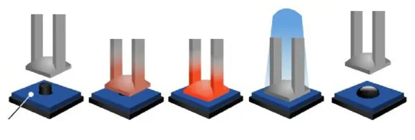
Figure 12: Heat Staking
Procedure:
- Class A Surface and Master Sections (Input)
- Class A Surface Examination for any discontinuities (Assessment)
- Determination of the Main Tooling Axis, and Side Tooling Axis if required
- Draft Analysis of Class A Surface
- Creation of Class B Surface
- Creation of Class C Surface
- Creation of Closed Surface (A-B-C)
- Creation of Flanges for fixation/attachment strategy
- Creation of B-Side Engineering features such as Heat Stakes, Ribs, 4 Way Locators, 2 Way Locators, Doghouse
- Assemble the Push Pins on Doghouses for Counterpart fixation
Inputs:
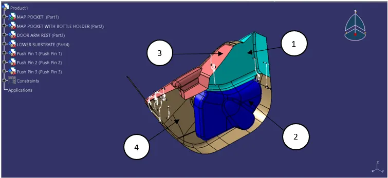
The following figure shows the Class-A Surfaces and the Master Sections as Inputs.
Code:
1: MAP POCKET
2: MAP POCKET WITH BOTTLE HOLDER
3: DOOR ARM REST
4: LOWER SUBSTRATE
1) MAP POCKET
- Map Pockets are generally used as storage spaces on the door
- The Map Pocket is divided into upper and lower halves
- The Upper half acts as an aesthetic enclosure for the inner parts
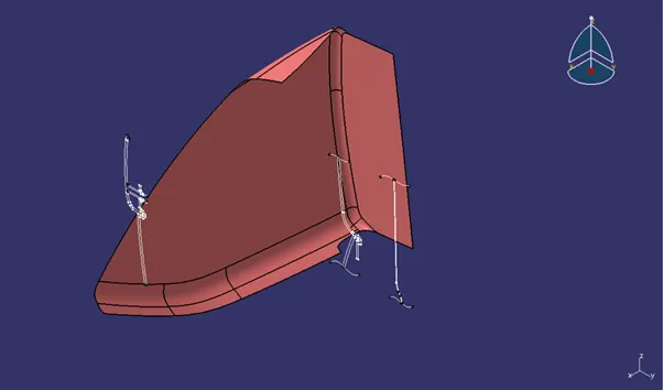
Figure 13: Map Pocket Input with Master Sections
Draft Analysis:
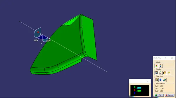
Figure 14: Draft Analysis of Class A Surface along the Main Tooling Axis
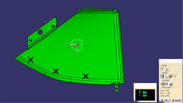
Figure 15: Draft Analysis of Class B Surface along the Main Tooling Axis
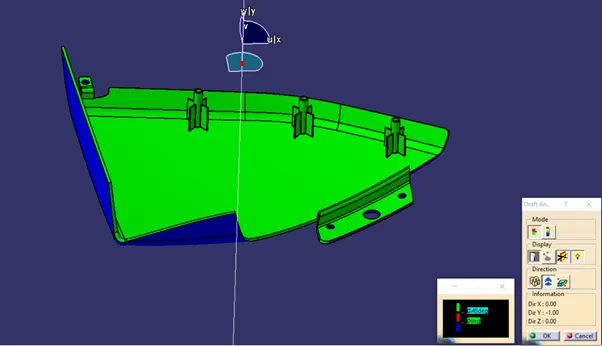
Figure 16: B Side features Draft Analysis along the Main Tooling Axis
Designed Component:
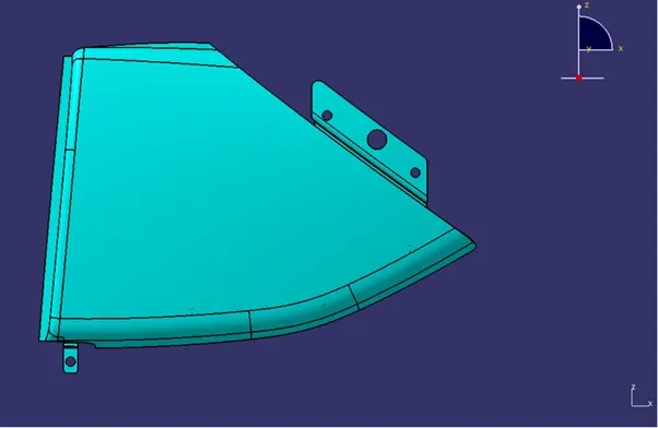
Figure 17: Front View
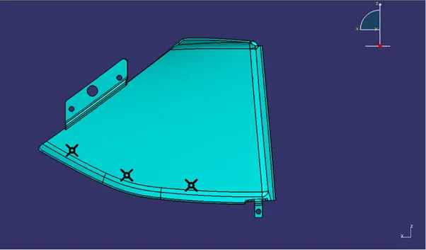
Figure 18: Back View
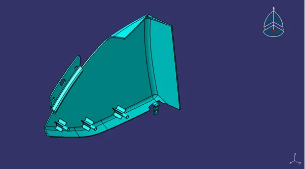
Figure 19: Isometric View
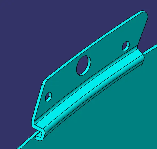
Figure 20: Flange 1
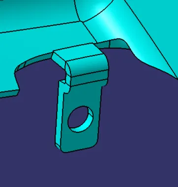
Figure 21: Flange 2
B Side Engineering features:
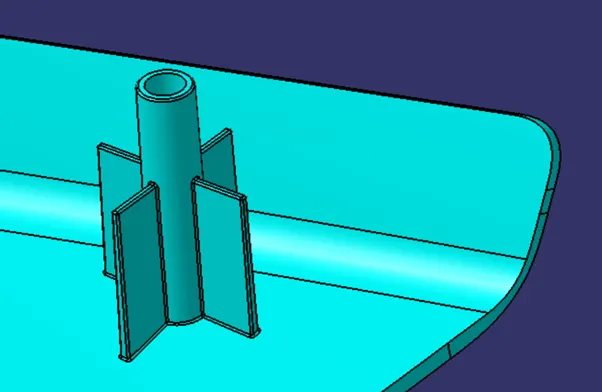
Figure 22: Heat Stake with supporting Ribs
2) MAP POCKET WITH BOTTLE HOLDER
- The Lower half of Map Pocket is used as a storage space on the door for Water Bottle
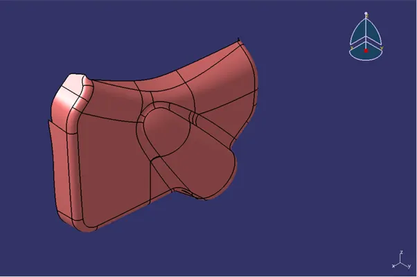
Figure 23: Map Pocket with Bottle Holder Input
Draft Analysis:
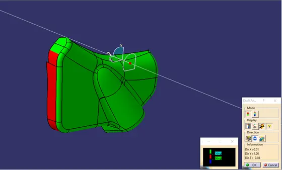
Figure 24: Draft Analysis of Class A Surface along the Main Tooling Axis
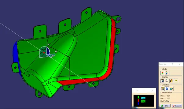
Figure 25: Draft Analysis of Class B Surface along the Main Tooling Axis
Designed Component:
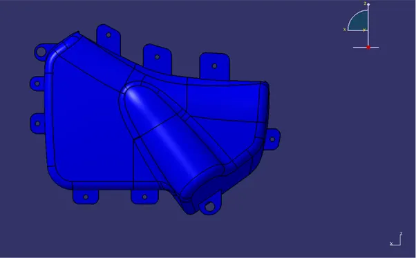
Figure 26: Front View
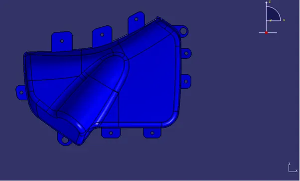
Figure 27: Back View
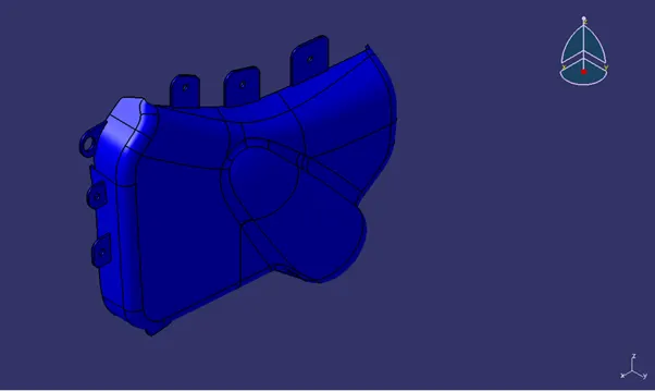
Figure 28: Isometric View
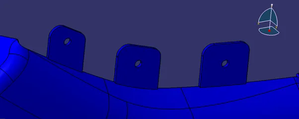
Figure 29: Flanges
3) DOOR ARM REST
- Door Arm Rest, as the name suggests, is the part where the driver or passengers can rest their arms on
- It may have a soft touch surface such as leather or any other soft material for comfort
- It also houses various electrical components such as the Power Window switches, Mirror adjustment switches, etc
- The Door Arm Rest also has a small storage space for coins, sunglasses, etc
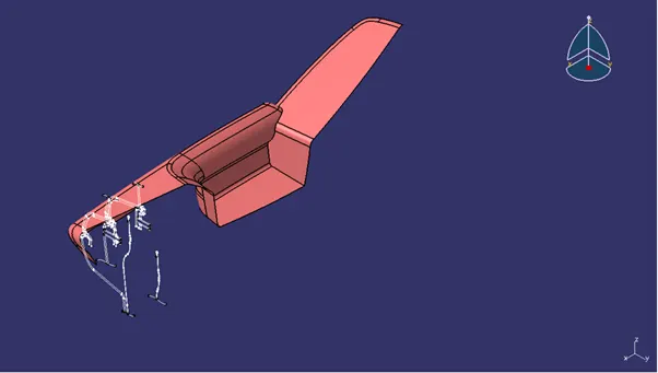
Figure 30: Input Class A Surface and Master Sections
Draft Analysis along the Main Tooling Axis:
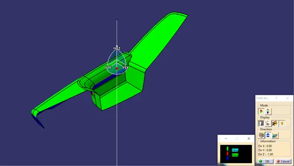
Designed Component:
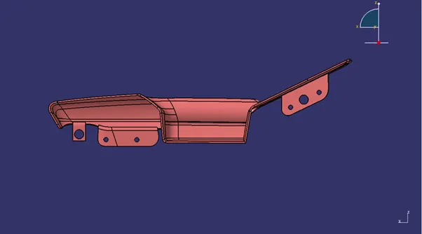
Figure 31: Front View
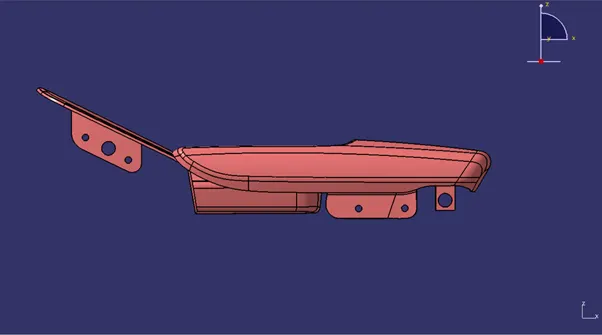
Figure 32: Back View
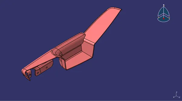
Figure 33: Isometric View
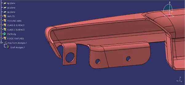
Figure 34: Flange 1
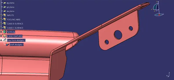
Figure 35: Flange 2
4) LOWER SUBSTRATE
- Lower Substrate is the encapsulating aesthetic part used in the door panel
- It houses various components such as the wiring harness, speakers, as well as fixation features
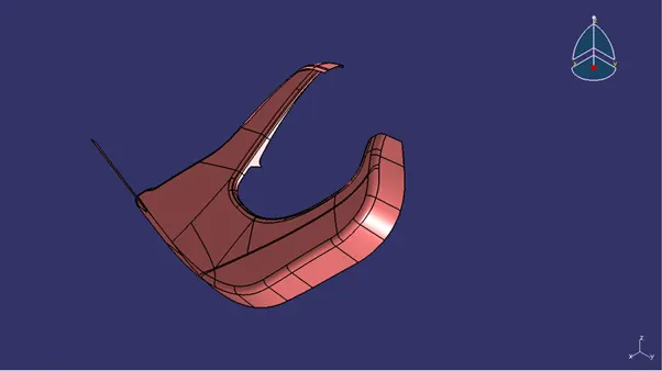
Figure 36: Input
Draft Analysis:
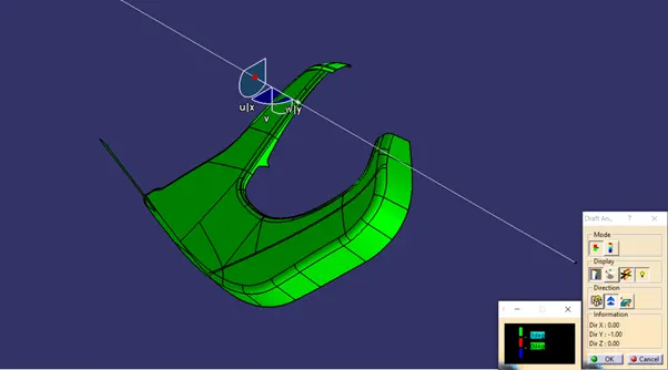
Figure 37: Class A Draft Analysis along the Main Tooling Axis
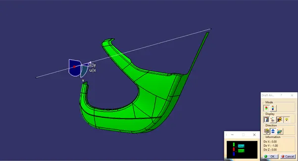
Figure 38: Class A Rear
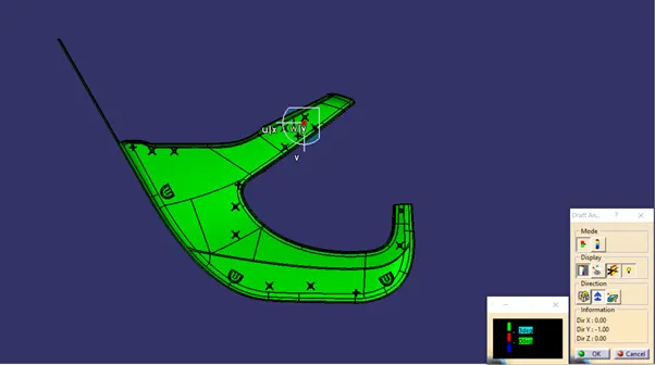
Figure 39: Class B Draft Analysis along the Main Tooling Axis
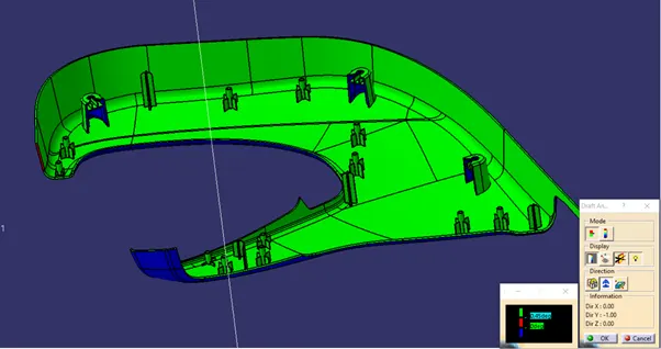
Figure 40: B Side features Draft Analysis
Designed Component:
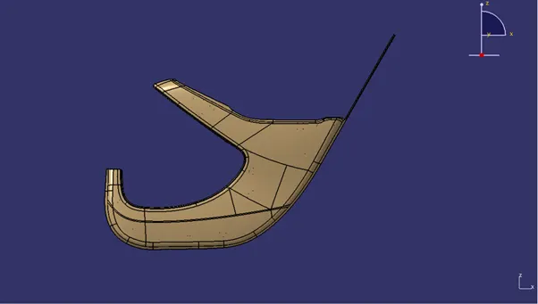
Figure 41: Back View
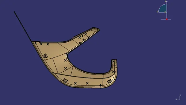
Figure 42: Front View
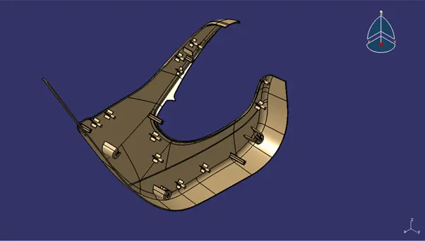
Figure 43: Isometric View
B side Engineering features:
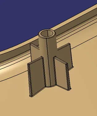
Figure 44: Heat Stake with Supporting Ribs
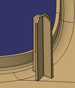
Figure 45: 4 Way Locator
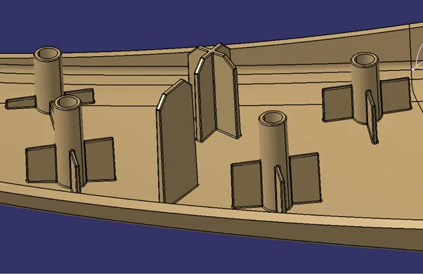
Figure 46: 2 Way Locator
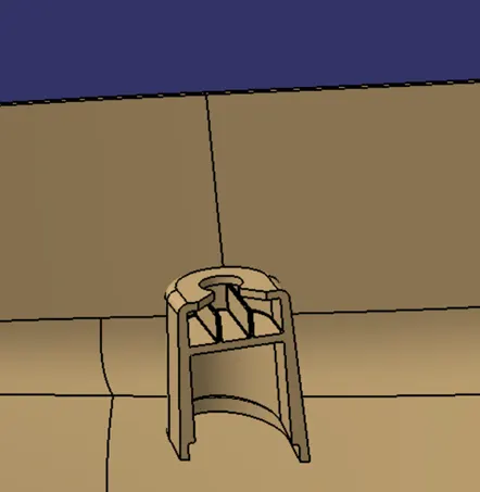
Figure 47: Doghouse
Final Assembly Door Panel Trim:
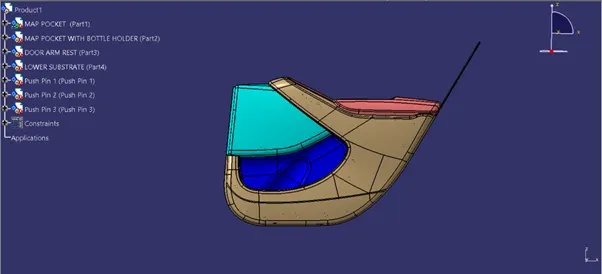
Figure 48: Back View
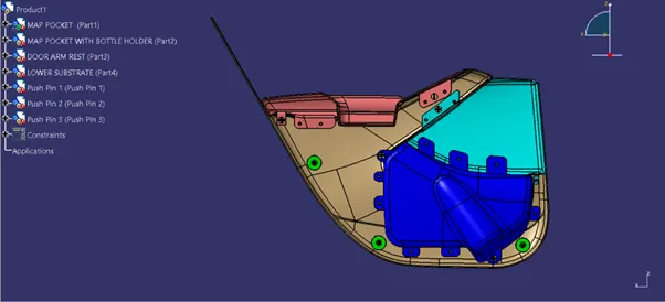
Figure 49: Front View
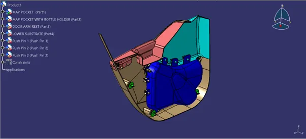
Figure 50: Isometric View
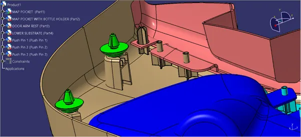
Figure 51: Detail View 1
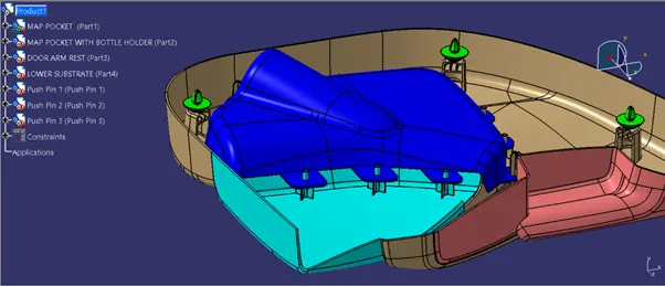
Figure 52: Detail View 2
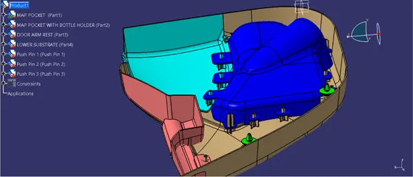
Figure 53: Detail View 3
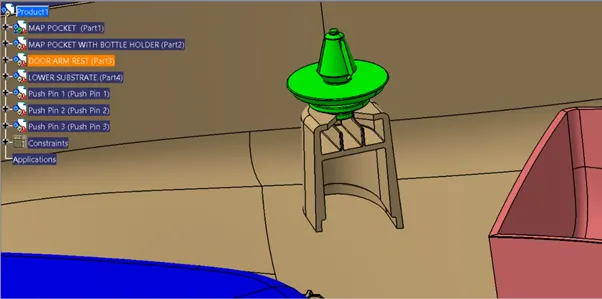
Figure 54: Detail View 4- Doghouse with Push Pin
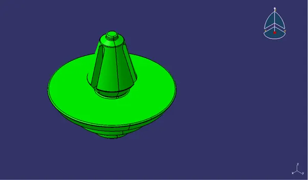
Figure 55: Push Pin
Conclusion: The Design of Interior Door Panel Trim by implementing the Plastic Product Design Rules and Guidelines using CATIA V5 have been completed. The Part Design, Assembly Design and Generative Shape Design Workbenches have been used for the same.