Week 9 - Project - Master Section Development
B PILLAR PROJECT REPORT
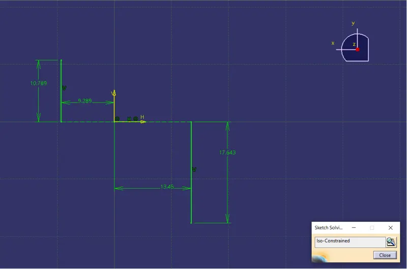
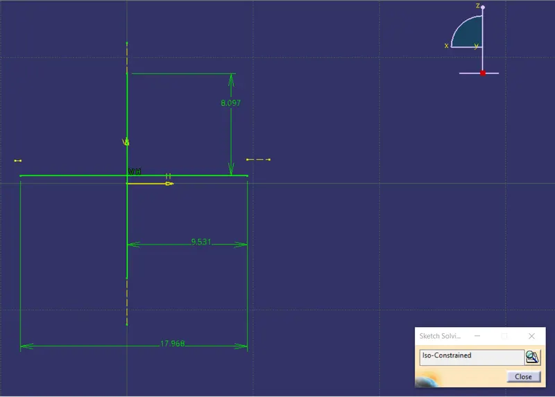
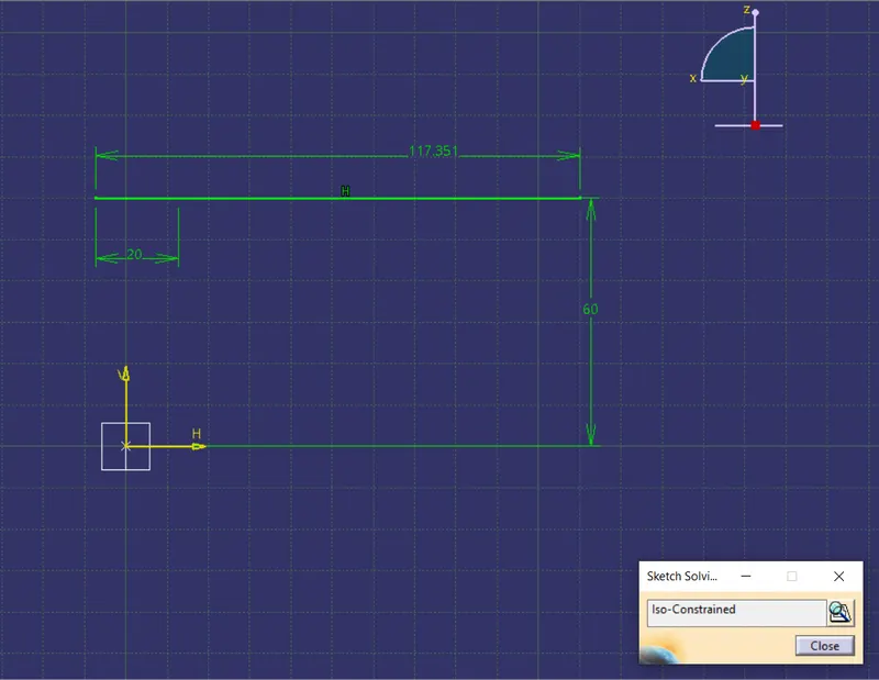
For creating the B Pillar Plastic component, from the given inputs: Class A Surface and Master Sections, the course of procedure is as follows
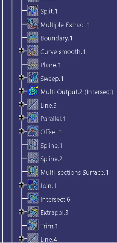
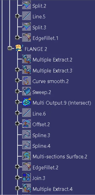
- Creation of Outer Flanges on Left and Right side as per the Master Sections
- Offset the Class A Surface to create the Class B Surface. The thickness of the component is measured from the master section
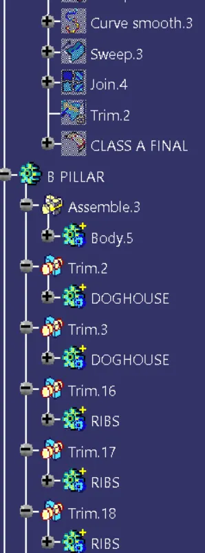
- Creation of Class C Surface
- Creation of Closed Surface
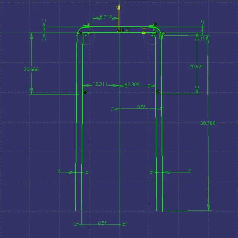
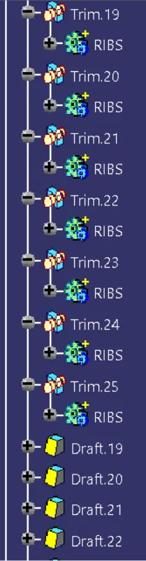
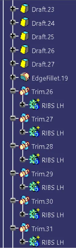
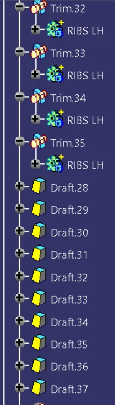
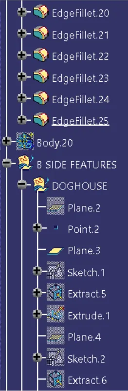
- The next step is to create the B-side features. These includes a Doghouse with a 4 Way Locator on either sides and Ribs each 50mm apart along the entire length of the component on either sides.
- The B-side features are designed according to the Master sections while ensuring that the design rules are being followed.

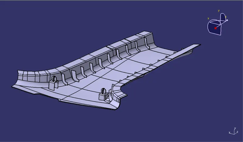
Isometric View
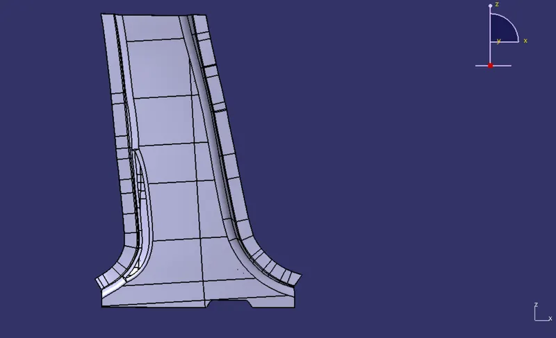
Front View
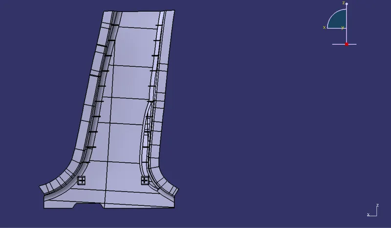
Side View
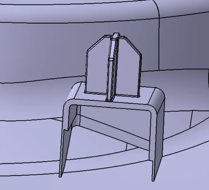
DogHouse with 4 Way Locator
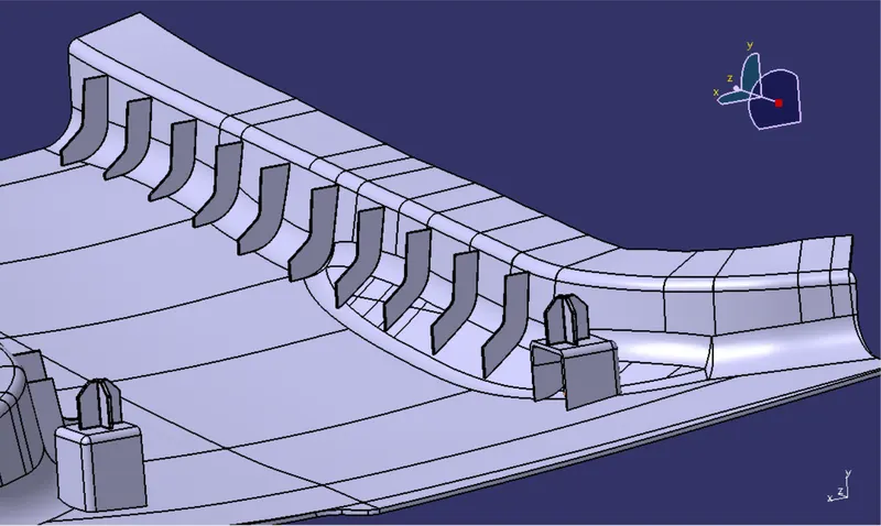
Ribs
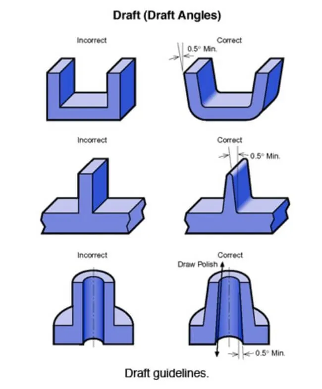
For successfully creating a component that is moldable or in other words that can be manufactured, Draft Analysis of the component should be carried out.
- What is a Draft?
Essentially, draft angles for injection molding are a design consideration that makes it much easier for a part to release cleanly from a mold. A draft angle is calculated as a degree measurement from the vertical axis of a mold, and it helps account for thermoplastic shrinkage, a practical reality of the injection molding process for most materials.
By accounting for thermoplastic shrinkage during the cooling process, draft angles greatly reduce friction between the finished, cooled part and the side of the mold. Not only does this create a much easier release process, it offers several other benefits, depending on the design of the part:
- Reduces the chance of damage to the part due to friction during release
- Reduces wear and tear and chances of damage to the mold
- Ensures a uniform, smooth, unscratched finish when required
- Ensures the integrity and uniformity of other surface finishes and textures
- Reduces overall cooling time by lessening or eliminating the need for unconventional ejection setups
- Most, if not all, of these benefits offer either direct or indirect overall production cost reductions
Draft Analysis of B Pillar
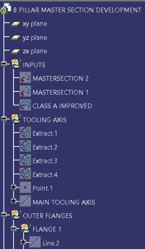
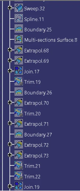
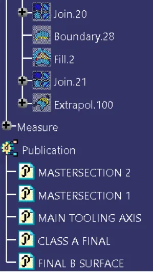
- Creation of Main Tooling Axis by bisecting method using the master sections
- Class A Surface
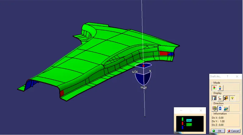
The Nominal draft for Class A Surface is 3 deg. The following figure shows that the entire Class A surface clears the Main Tooling Axis as per the Draft Analysis; except for the two red patches as seen in the figure
Patch 1
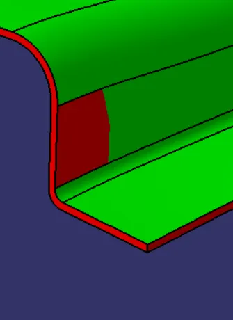
The Draft Angle is found to be 2.63deg
Patch 2
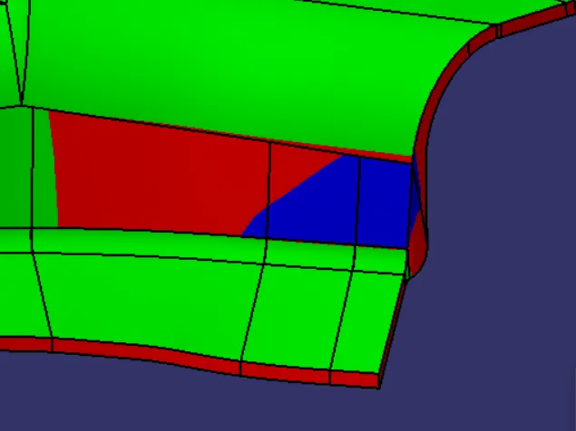
The Draft Angle is found to be 2.923deg
- Class B Surface
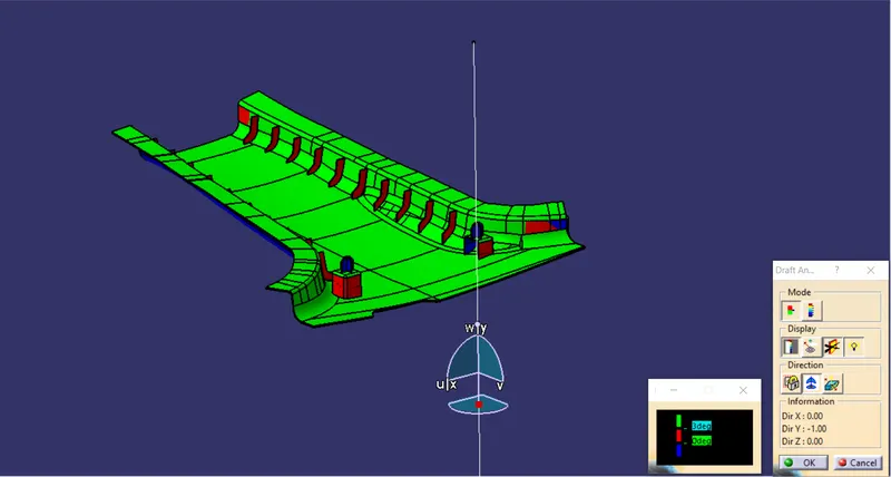
Since the Class B Surface is offseted from the Class A Surface, hence it also clears the Main Tooling Axis, except for the two patches as seen in the figure
Patch 1
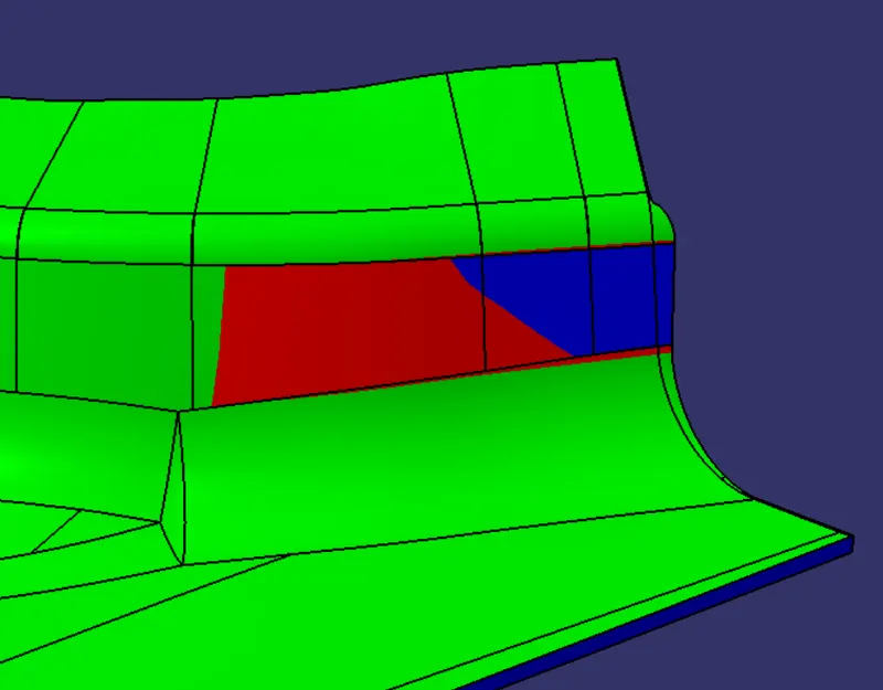
The Draft Angle is found to be 2.869deg
Patch 2
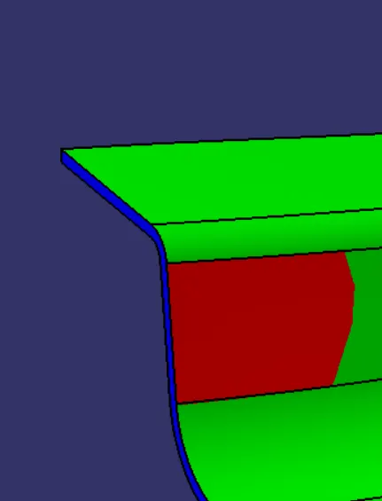
The Draft Angle is found to be 2.32deg
- Class C Surface- The Class C Surface is found to clear the Main Tooling Axis as indicated by the Draft Analysis
- B-side features
- DogHouse with 4 Way Locator
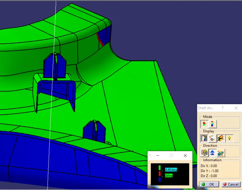
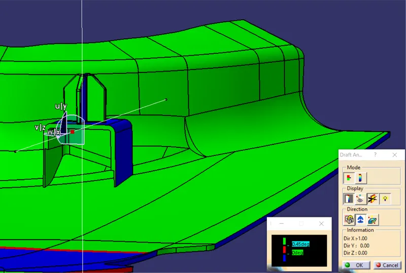
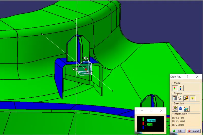
The Nominal draft angle for the doghouse and 4 way locator is 0.5deg.
2. Ribs
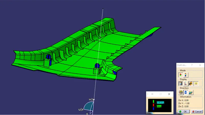
The outside surfaces of Doghouse are cleared by the Main Tooling Axis whereas for the inside surfaces of Doghouse, the Side Core Axis is created and the Draft Analysis is carried out along the Side Core Axis wherein it is seen that the inside faces of the Doghouse clears the Side Tooling Axis for a nominal draft angle of 0.5deg which is the required output
Draft Analysis along the Side Tooling Axis