Project 2
The core voltages and currents of next-generation, highperformance microprocessors are approaching 1 V and
130 A. At the same time, tight steady-state and dynamic tolerance requirements for core voltages present a big challenge for powering this type of load. To decrease the impact of PCB board and component parasitics during high-slew-rate microprocessor transients, the dedicated power supply and decoupling capacitors have to be placed as close as possible to the microprocessor.
The interleaved synchronous buck converter is a popular solution to supply high-current microprocessors because of the lower input and output current ripple and higher operating frequency of input and output capacitors in comparison with the one-channel solution. Interleaving also enables spreading components and dissipated power over the PCB area, but it requires equal current sharing between the channels. Different control approaches to achieve good current sharing and fast transient response
Interleaved Buck Converter for a Non- Linear System is as shown below:-
We will design an Isolated Interleaved Forward Buck Converter for this application.
Given Conditions:-
Input Voltage:- 60 V.
Output Voltage:- 3 V
Output Current:- 100 A.
Efficiency> 85%
Assumption:-
Let the Duty Cycle for the converter be D= 0.5
Switching Frequency (Fs)= 100 kHz.
Calculation Performed:-
We are aware about the Voltage Ratio of a Feed Converter as:-
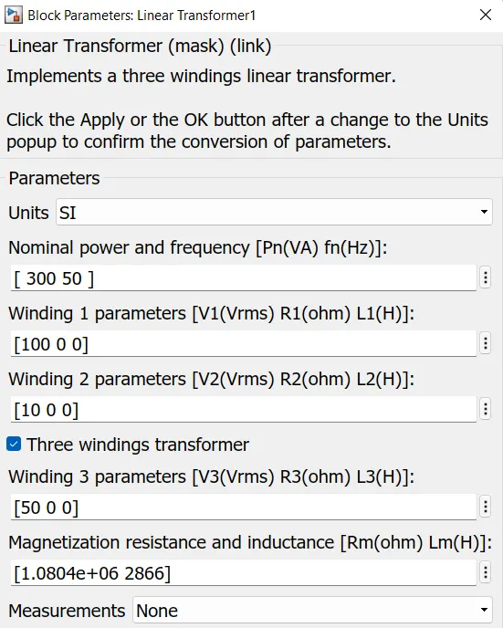
Vout/ Vin= D* (N2/N1)
3/60 = 0.5 (N2/N1)
N2/N1 = 1/10
Considering the turn ratio on the primary side to be 100 turns,
So the turn at the Secondary coil will be 10 turns.
Also, We know that
D (1+(N3/N1))<1
0.5 (1+(N3/100))<1
Therfore N3 < 100
Choosing N3= 50 turns
So N1= 100 turns, N2= 10 turns and N3= 50 turns.
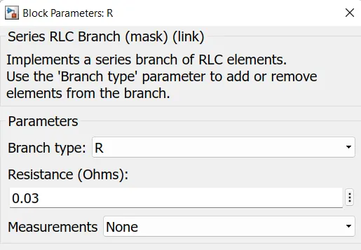
Load Resistance (R) :- Vout/ Iout
R= 3/100 = 0.03 Ω
Output Power (Pout) = (Vout*Vout) / R
Pout= 3*3 / 0.03 = 300 Watt.
Total Inductor Current will be sum of current flowing through Inductor L1 and L2
IL= IL1 + IL2
Since the current through both the inductor will be equal to output current which is 100 A.
So designing both the Inductor having same value, which means that bothbthe inductor will have same amount of current flowing across them.
Therefore, IL1+ IL2= 100 A
and IL1= IL2 = 50A.
Designing both the inductor for 10% ripple from the average inductor current.
△IL1 = 50 * 0.1 = 5 A.
△IL2 = 50 * 0.1 = 5 A.
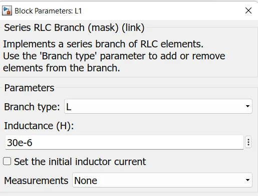
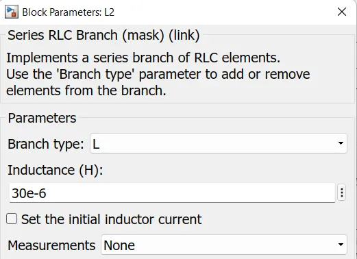
The value of Inductance can be calculated from the below formiula:-
L1 = Vout * (1-D) / (Fs*△IL1)
L1= 3* (0.5) / (1000000* 5)
L1= 30uH = L2
Since we have consider both of the capacitor to be of same capacity.
Designing the output capacitor for 1% volatge ripple of the average Capacitor voltage.
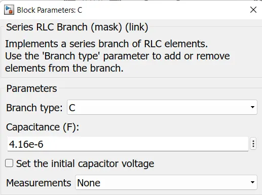
We can calculate the value of Capacitance from the below formula:-
C = (1-D) / (8* L* (Fs^2)* △Vo/Vo)
C= 0.5 / (8* (30 * 10^-6) * (10000 *10^6) *0.01)
C= (0.5/ 1.2) * 10^-5
C= 4.16 uF.
Simulink Model:-
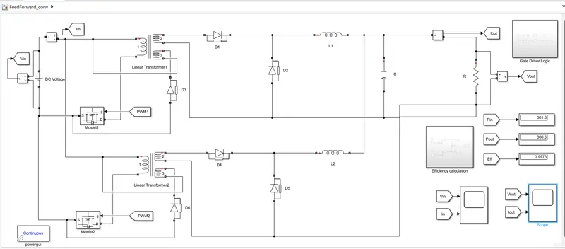
Block Used:- Dc Voltage Source, Mosfet, Diode, Linear transformer, Goto and From block, Series RLC branch, Voltage Measurement, Current Measurement, Powergui, Sum, PID Controller, DC-DC pulse generator, gain, product and Scope
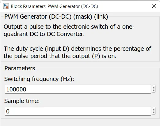
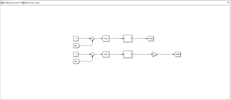
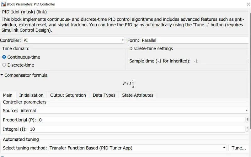
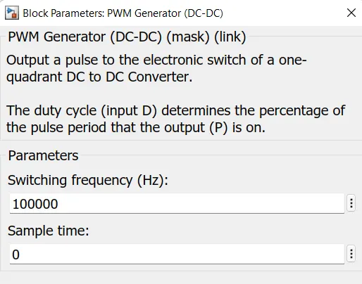
Gate Driver Logic:- The gate driver logic is containing the reference output voltage which is 3 V and the output voltage is applied to the negative input of the sum block. Then the error signal is passed through the PI controller and then this actuated signal is passed through the DC- Dc pulse generator having a frequency of 100MHz.
PI Controller:-
DC-DC pulse generator:-
Efficiency Calculation:- The efficiency is calculated by dividing the input power from the output power and can be observed as:-
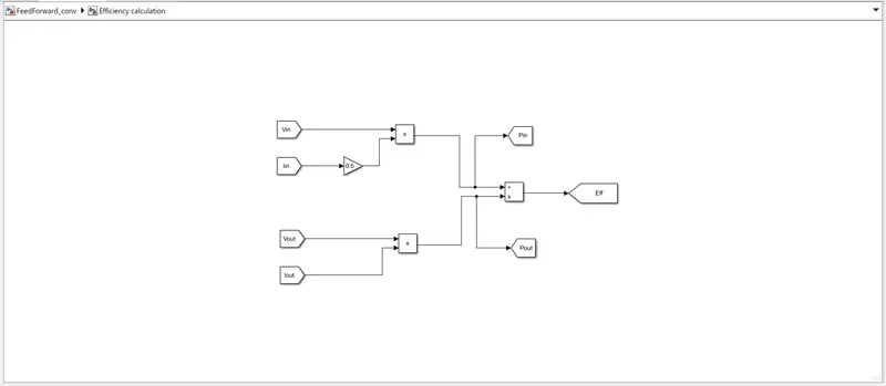
The Output voltage is multiplied with Output current to give Apparent output power and then this Output power is divided by the input powe to get the efficiency.
Results:-
The plot are obtained after running the model for a simulation time of 0.5 sec.
a) Input Voltage and Current:-
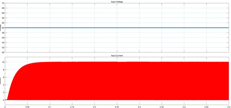
Input Volatge is constant as 60V and the output current can be seen as:-
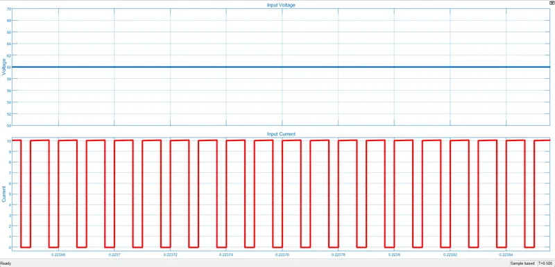
The Input current ripple between the value of 0 and 10A. So to find the average input current of we have taken the average of 10 and 0 which is 5 A for simplicity of calculation.
b) Output Voltage and Current:-
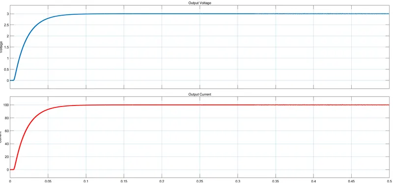
The output current is similar to the output voltage and it reaches the value of 3V at time 0.1 sec.
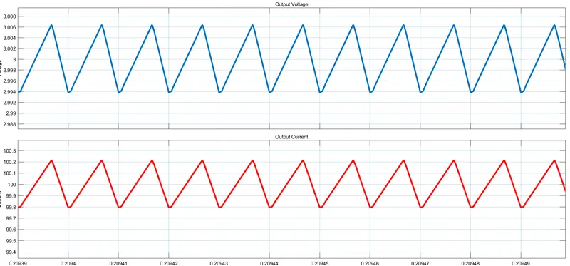
The ripple in the Output voltage is around 2.994 to 3.006 V which is less than 0.4% of the required output average voltage.
The ripple in Output current is around 99.8 A to 100.2 A which is less than 0.4% of the required output average current.
The Efficiency calculation is shown below:-
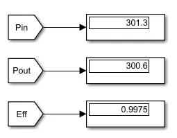
here the Input power comes to be 301.3 watt and Output power to be 300.6 watt. Therefore the efficiency comes out to be 99.7% which is greater than 90% .