Week-6 Challenge: EV Drivetrain
Challenge URL- https://drive.google.com/drive/folders/1TnT0di5afFmCeXuamH3htJTJ6X4jRYSh?usp=sharing
Task- 1 Types of Power Converter employed in Electric and Hybrid Electric Vehicle:-
For Electric or Hybrid Electric Vehicles Power converter can be considered as brain of the vehicle. They are the connecting link between power source and transmission of the vehicle. These converter can be very helpful for increasing the overall efficiency of the vehicle. These can be classified as:-
i) AC to DC Converters:- These converters are majorly used in HEV/PHEV at the charging station where the input supply is Alternating and the battery present inside the vehicle is DC so these types of converters are used here.
ii) DC- AC Inverters:- A DC-AC inverter supplies the high power electric motor and utility loads such as air-conditioning system. With these inverters different level of speed can be obtained from the motor by adjusting the frequency of the alternating current.
iii) DC-DC converter:- DC/DC converter is used to boost the Fuel Cell voltage and to regulate the DC-link voltage.The batteries of an electric vehicle typically output several hundred volts of DC. The electric components inside the vehicle, however, vary in their voltage requirements, with most running on a much lower voltage. This includes the radio, dashboard readouts, and in-built computers and displays and these accessories can be powered up with the help of DC-DC converters.
Task 2:- From the question we have to calculate the steady state speed of the vehicle.
Given Inputs:-
Battery Voltage(Vin)- 72 V
Rated armature Voltage(Va) = 72 V
Armature Current(Ia) = 400 A
Armature Resistance(Ra) = 0.5 `ohm`
Kϕ= 0.7 Vsec.
Frequency(f)- 400 hz.
Duty cycle(d)= 0.7
Tveh= 24.7+(0.0051)ω^2
Since we know that the voltage across the motor will be Vin*d which will be (Vm)= 72*0.7= 50.4 V
Also we have studied that the relation of angular velocity and Torque for the motor is given by the expression:
ωm= Vm/Kϕ- (Ra/((Kϕ)^2))*Tm----------------------------(a)
where ωm is the angular velocity of the motor in rad/sec.
Tm is the Torque of the motoe in Nm
so rearranging eq. (a) in terms of torque we get the expression as:-
Tm= ((Vm/Kϕ)-ωm)*((Kϕ)^2/Ra)
Tm= Vm.Kϕ- (ωm*(Kϕ)^2)/Ra
So putting value of all the expression we wil get the value of Tm in terms of ωm
Tm= (50.4*0.7)- (0.49/0.5)*ωm
Tm= 70.56-0.98ωm ------------------------------------------(b)
As we know that for steady state calculation of vehicle speed both the vehicle and motor Torque equation meet at a point and that point is the steady state speed
So Tveh= Tm (for Steady state cond)
so equating equation (a) and (b) we get,
24.7+(0.0051)ω^2= 70.56- 0.98ωm
Solving these equation we get,
0.0051ω^2+ 0.98ω -45.86----------------------------------(c)
So by using Shreedharacharya Formula to solve quardatic equation (c) we get
x= (-b±√b^2-(4ac))/2a
x=(-0.98±1.377)/0.0102
we get values of x as 38.9215 and -231.0784 rad/sec
We will neglect the negavtive value of x so the angular velocity at steady state will be 38.92 rad/sec.
Task-3 To develop a mathematical model using the equation given in challenge.
Block Used:- Constant, Gain, Sum, Ramp Signal, Product, XY graph
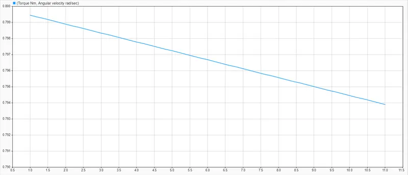
Working:- As we are given to plot the Torque- speed charterstic of the DC motor using a simulink model. So we have taken the input such as Voltage and Motor Constant by ourself which is 48 V and 60 Vsec. And Torque is given through a ramp signal which changes its value on each and every step. Now we are aware of the motor Torque speed equation which is as follows:-
ωm= Vm/Kϕ- (Ra/((Kϕ)^2))*Tm
So making an arrangement with the help of model and observing the result as follows.
Observation:- Plotting the Torque on X axis and Angular Velocity on Y axis of the XY Graph and running the simulation for 10 sec, we get the following result as shown in the figure attached below.
Result :-
Task-4 Comparison between Induction and DC Brushless Motor.
Wally Rippel a power Electronic Engineer who currently works at Tesla Motors discuss about the near future trend of Electric vehicle and the motor requirement for the propulsion of the required Torque for the vehicle. In his earlier days when he was working with AeroVironment he helped developed EV1 for General Motors. He very ironically discuss about the past trends which were used like Lead Acid Battery, DC brush motor and Contactor controllers which are nowerdays replaced by the Lithium Ion in case of battery, Dc brush motor by either the Dc brushless motor or by Induction motor and the contactors controllers by Modulating Inverters. He also talk about the near future scope of both the brushless and Induction motots and finds that they might be stable for many upcoming years. Now let us discuss about the working of both the motors.
Working Of Brushless DC Motor:-As per the Lorentz force law whenever a current carrying conductor placed in a magnetic field experiences a force. As a consequence of reaction force, the magnet will experience an equal and opposite force. The rotor of the brushless DC motor includes two or more permanent magnets which generates the permanent magnetic field. In the BLDC motor, the current carrying conductor is stationary and the permanent magnet is moving. As the rotor rotaes it is necesary to change the magnitude and polarity of the static stator winding continously so as to get the constant torque output. This control of continously varying magnitude and polarity is done by an inverter. Without the use of inverter Brushless motor are useless.
Working of an Induction Motor:- Induction motor were discovered by Nikola Tesla around 1889, It work on the principle of Electromagnetic Induction i.e. electromotive force induces across the electrical conductor when it is placed in a rotating magnetic field. Unlike Brushless motor it did not have permanent magnets but it have stacked steel lamination with buried perpheral conductors to form a shorted structure. The essential constructional diffrence lies in the rotor construction of both the motors. Current flowing in a stator wdg. produces rotating magnetic field which enters the rotor. The frequency of these magnetic field when seen from the rotor respective is the difference between the applied one and the one which gets dissipated in rotor rotational. An induced voltage is induced inside the shorted structure of rotor which is a result of the diffrence between the frequency of Supply and rotor frequency. and this diffrence is known as slip of Induction motor. And the rotor is short circuited through end rings so current flow inside the rotor which interact with original magnetic field to produce the required torque.
Earlier Induction motor were mostly used as a constant speed motor as they have limited starting torque and running peak torque capability is also less when compared with the DC motors. After the introduction of Inverter technology these induction motor can be powered up from a DC source or battery too. It can also be used at application were variable speed requirement are there as by adjusting the inverter frequency. After having some feedback loops such that the inverer produces But still the torque performance of the induction motor is low when compared with the DC motor
Differences:-
Controls:- Dc Brushless motor are position specific and induction motor are speed specific
Heating effects:- Dc brushless motor very less heat is generated in the rotor and rotor cooling is also easy also peak point efficiency is higher in these motor.
Operating point:- DC brushless can operate at unity power factor while the best power factor for induction motor is about 85%. Also peak point energy efficiency of Dc drive is higher as compared to induction drive.
Losses:- Since the Dc brushless motor have permanent magnet so controlling of flux density (B) is not possible. Which means that the losses such as Eddy, Hystersis and Copper losses must be minimized to get best efficiency since the B is not adjustable so looses are more in DC brushless motor as compared to induction motors. As they have V/f control through which means at light loads the volatge through inverter will reduce limiting current and thus losses too.
Size:- As the size of the Dc Brushless motor increseas the magnetic losses increases proportionally and also part load efficiency drops and induction motor losses are not dependent on size.
Costing:- Permanent magnet are much costlier and expensive and are difficult to control in the vivinity of ferromagnetic materials. Induction motor are less expensive.
Complexity:- The control laws of induction motors are complex and difficult to understand. Achieving stability over the entire torque speed range and over temperature is more difficult with inducction motor when compared to the brushless dc motors
Conclusion:- Dc Brushless motor will dominate in Hybrid and Plug In Hybrid vehicle while Induction motor will be dominating for the high performance pure electric vehicles.