Project 1 Mechanical design of battery pack
Task:- Prepare a detailed battery pack drawing along with its enclosure. State your assumptions.
26650 cells are best for Power Safety Life applications. They deliver very high power due to their use of patented Nanophosphate battery technology. Based on lithium iron phosphate chemistry (LiFePO4), the cells are inherently safe over a wide rangeof temperatures and conditions. Whether the application requires outstanding cycle life or stable float reliability, the 26650 cells are suitable for a wide variety of power, pulse, or stand-by applications.
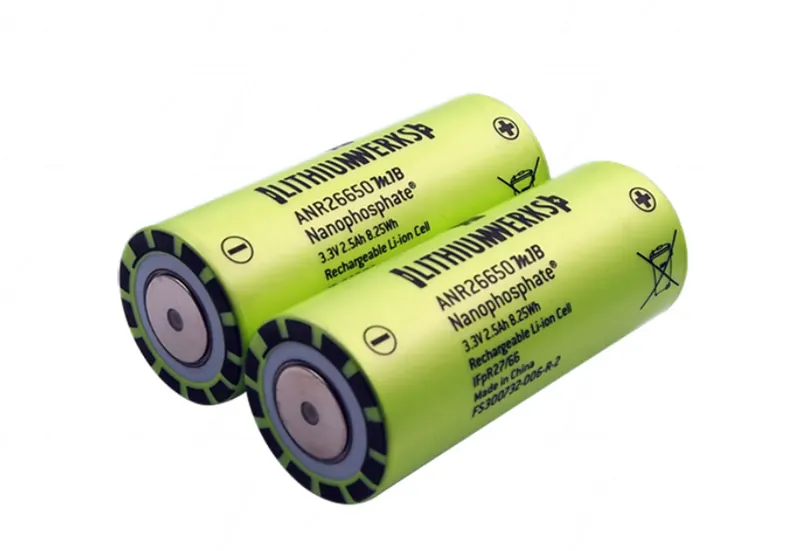
Nanophosphate battery technology offers thermal-stable chemistry, faster charging, consistent output, low capacity loss over time, and superior total cost of ownership (TCO). It provides the foundation for safe systems while meeting the most demanding customer requirements. Multiple layers of protection are employed at the chemistry, cell and system
level to achieve an energy storage solution with superior safety and abuse tolerance compared to metal oxide lithium-ion chemistries.
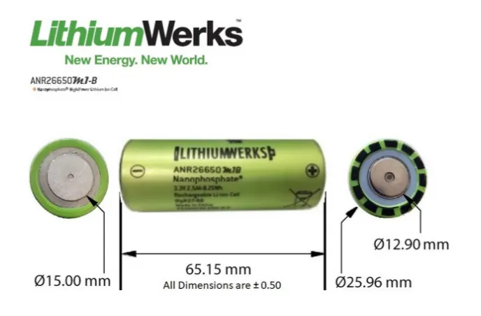
Dimension of ANR26650M1-B cell
Application of ANR26650M1-B cell
i) Commercial Solution:-
- DataCentre UPS
- Telecom Backup
- IT backup
- Autonoumsly Guided Vehicle (AGVs)
- Industrial robot and material handaling equipment
- Medical devices
ii) Government Solution:-
- Military Vehicles
- Military Powergrids
- Soldier Power
- Directed Energy
iii) Grid Solution:-
- Frequency regulation
- Renewables Integration
- Reserve capacity
- Transmission and Distribution
iv) Transportational solution
- Commercial Vehicle
- Off-highway vehicle
- Passenger Vehicle
Specification of ANR26650M1-B cell
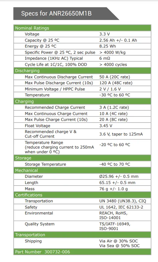
Cell Characterstics:-
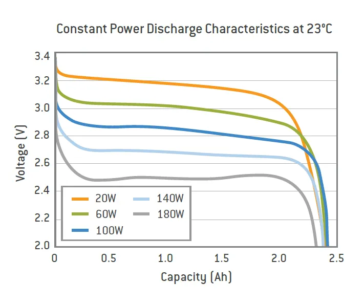
Constant Power Discharge Characterstics (23 deg C)
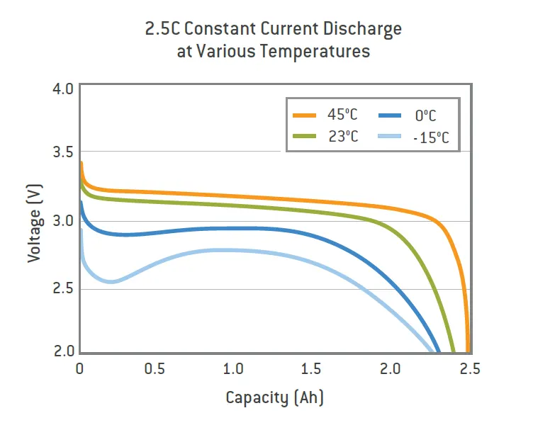
Constant Current Characterstics (23 deg C)
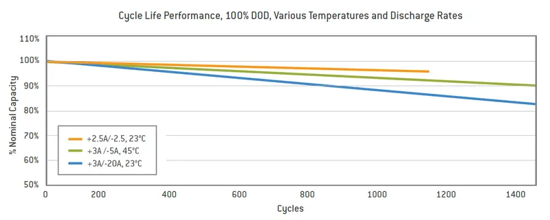
Cycle Life Performance at different Temperature and Discharge Rate
Battery pack Architecture:-
All high voltage battery packs are made up from battery cells arranged in strings and modules. A battery cell can be regarded as the smallest division of the voltage.
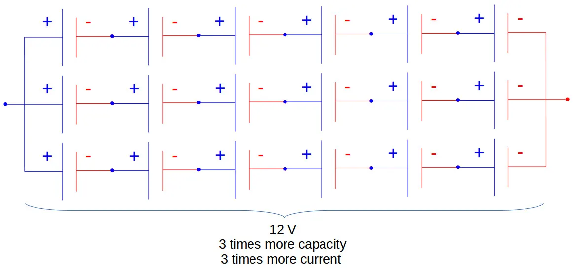
Individual battery cells may be grouped in parallel and / or series as modules. Further, battery modules can be connected in parallel and / or series to create a battery pack. Depending on the battery parameters, there may be several levels of modularity.
The total battery pack voltage is determined by the number of cells in series. For example, the total (string) voltage of 6 cells connected in series will be the sum of their individual voltage (each cell is of 2 V).

In order to increase the current capability the battery capacity, more strings have to be connected in parallel. For example, 3 strings connected in parallel will triple the capacity and current capability of the battery pack.
Battery pack Calculation:-
Given:-
Battery pack capacity:- 18 KWh.
a) Volume of each cell :- Volume of cylindrical cell is given by the following expression
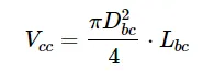
where D is diameter of cell (26 mm) and L is length of cell (65 mm)
In our case , Volume of single cell come out to be= π*((0.025)^2)*(0.065)/4
Volume of each cell is approx 35 mm^3.
b) Battery cell energy:-
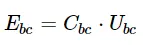
where Ebc is battery cell energy in Wh, Cbc is Battery cell capacity (2.5 Ah), Ubc is cell voltage (3.3 V)
Ebc= 8.25 Wh.
c) Volumetric Battery cell energy density :-
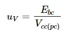
Ebc= 8.25 Wh and Vcc= 35e-6 m
Volumetric battery cell energy density = 235714.3 Wh/m^3.
attery pack total energy:-
It is given in the task and it is 18 Kwh.
e) Number of battery cells connected in series Ns :- in a string is calculated by dividing the nominal battery pack voltage Ubp to the voltage of each battery cell Ubc . The number of strings must be an integer. Therefore, the result of the calculation is rounded to the higher integer.
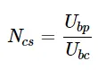
Let us consider the battery voltage of the pack to be 330 V and the cell voltage is 3.3 V
So no of cell connected in series will be:-
Ns= 330/3.3= 100.
f) Energy content of a string:- Ebs [Wh] is equal with the product between the number of battery cells connected in series Ns and the energy of a battery cell Ebc [Wh].
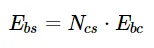
Ebs= 100*8.25= 825 Wh
g) Number of strings of the battery pack:- is calculated by dividing the battery pack total energy Ebp [Wh] to the energy content of a string Ebs [Wh]. The number of strings must be an integer. Therefore, the result of the calculation is rounded to the higher integer.
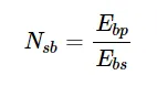
Nsb= 18000/825 = 21.81
Nsb= 22
All this 22 strings will be connected in parallel.
h) Battery pack capacity Cbp [Ah] :- it is calculated as the product between the number of strings Nsb [-] and the capacity of the battery cell Cbc [Ah].
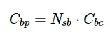
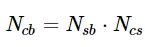
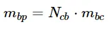
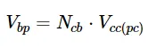
Since we have have 100 cells in a module which are connected in series and there are 22 such module which will be connected in parallel to constitute a battery pack. The battery configuration will be 100S22P.
This construction of the battery pack consist of several process which are done to get the end result as a battery pack.
1) Choosing The right battery strip:- to make the battery pack we have to connect those cells together by means of nickel strip or thick wire. Nickel strip are widely used for this process. There are generally two type of nickel strip used in the market :- nickel plated steel strips and pure nickle strip. Pure nickel have much lower resistance than the steel plated one but they are costlier. Low Reistance means less heat development during charging and discharguing and hence longer useful battery life. Nickle strip come with different dimension and length one should choose the strip wisely.

2) Spot Welding vs Soldering:- there are two option to connect those cells, they can either be attached by soldering or by spot welding. The best choice is spot welding but it is much costlier.

Soldering:- There is need to apply a lot of heat and this doesn't dissipate quickly. This enhances the chemical reaction in the cell which damage the ultimately life of the cell by decreasing the cell performance.
Sure, with the right soldering iron this issue can be minimized, but it's difficult to completely eliminate. If we don’t do things just right, that amount of heat directly on both sides of a cell will certainly affect its long-term performance.
Spot Welding:- Spot welding is the most common method used to build any battery pack. This is because spot welding enables the cells to be joined together without adding a lot of heat. Also, each spot weld takes far less time than an equivalent soldered connection would.
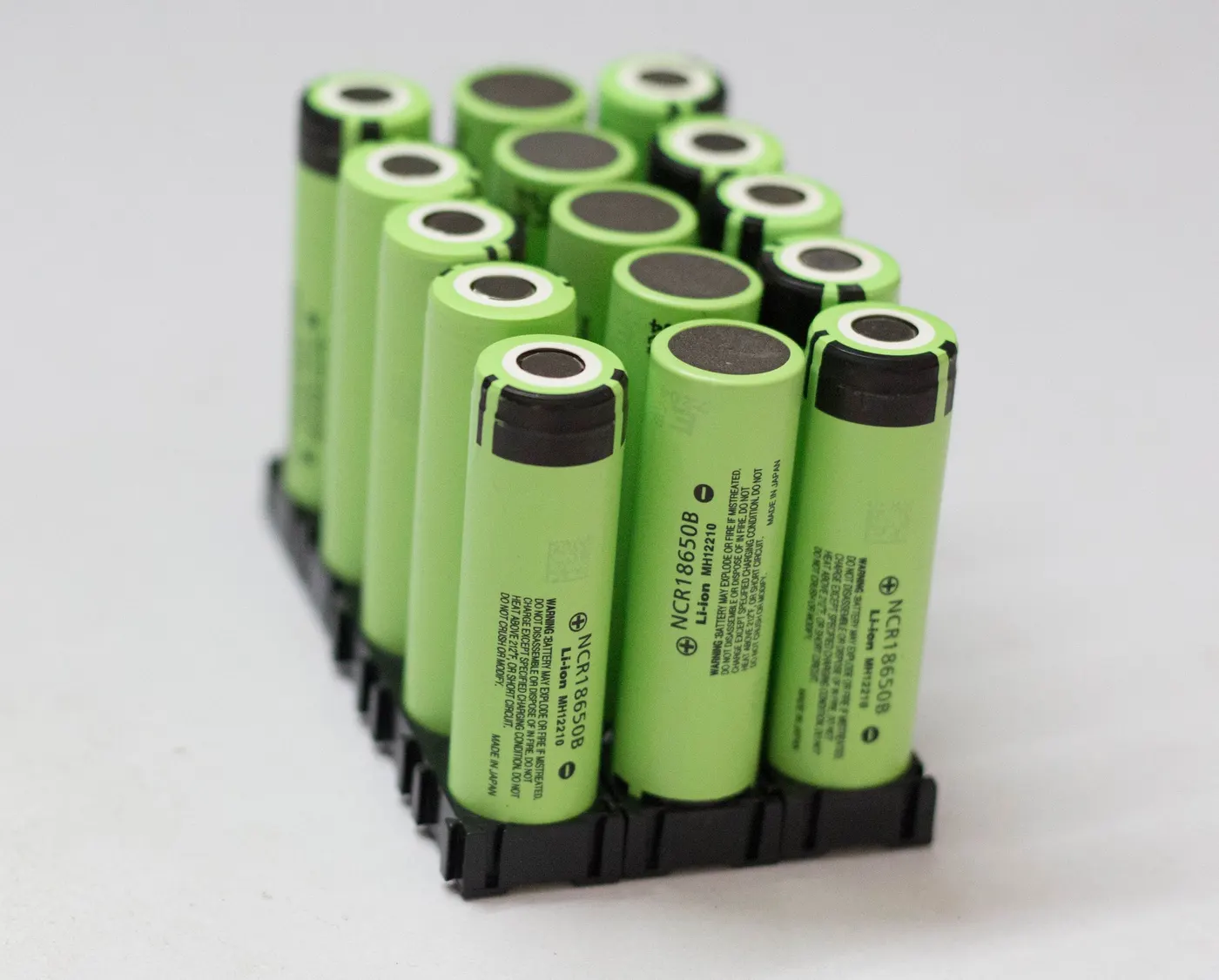
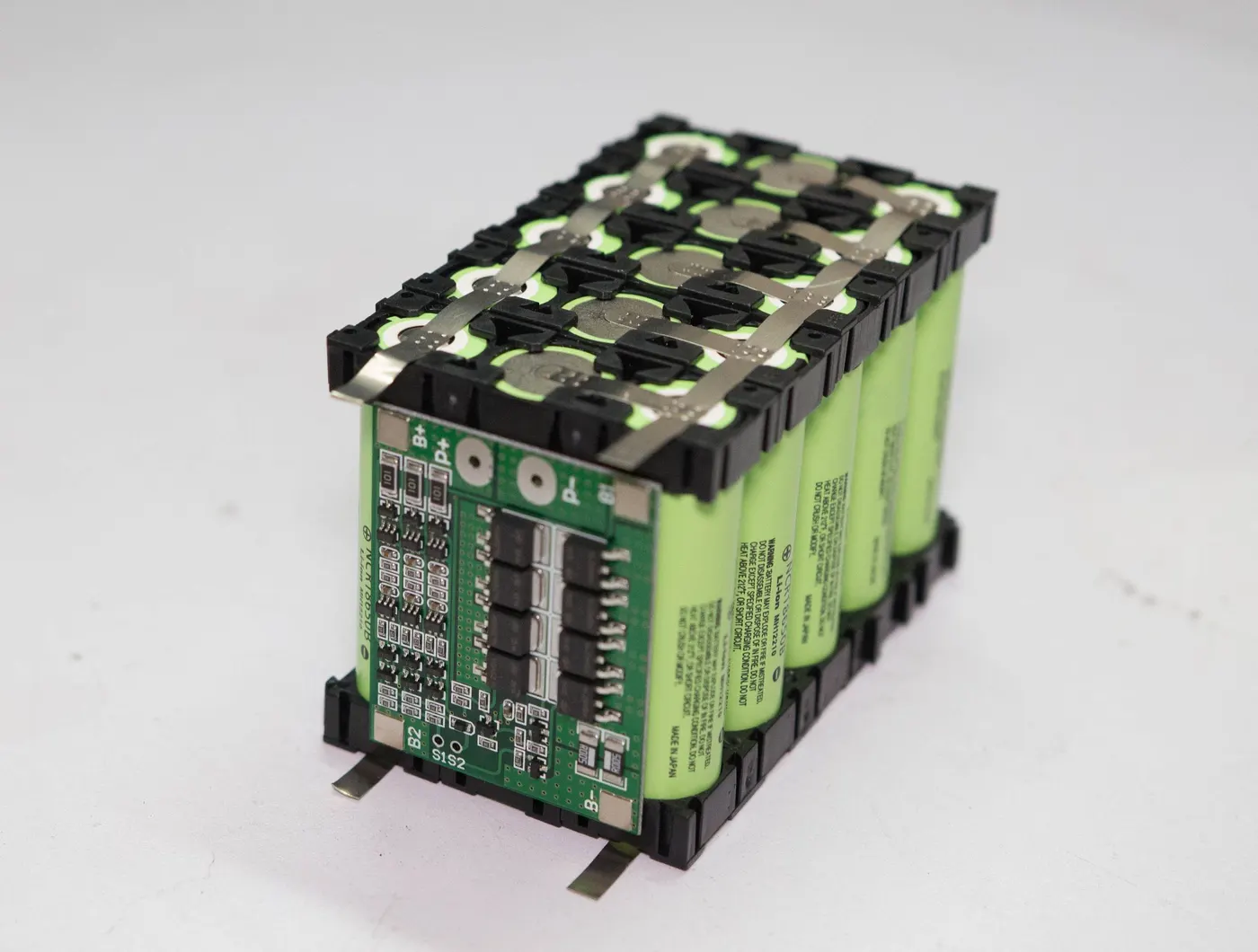
3) Assembling the cells together using cell holders:- Place the first parallel group of cells positive side up. After that, place the second parallel group negative side up, and so on. The cell holders will have notches on the side that allow them to be interlocked.
Connect cell holders together to form the needed arrangement of cells for our battery pack. While it is possible to simply hot glue the cells together, using cell holders gives your battery pack better cooling characteristics among other benefits.
Cell holders provide several advantages:
i. Cell holders provide critical spacing between the cells. This allows for much better cooling characteristics as compared to cells that are in direct contact with each other.
ii. Using cell holders makes our battery pack more solid.
iii. Cell holders give our battery pack an element of vibration resistance.
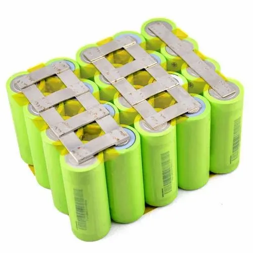
4) Spot weld the cells Together:- Before welding, be sure to prepare the nickel strips. The easiest way to do this is to lay your nickel strip on top of your parallel cells. Make sure that it covers all cell terminals. It's always good to leave around 10mm of strip for connecting the BMS sense wires. Remember, solid nickel strip with a thickness of 0.015 inches can carry about 1 amp of current per millimeter of width.
For series connections, simply cut small nickel strips to fit between your P groups.
Start by connecting the negative terminal on the first parallel group to the positive terminal of the second group, and so on, all the way down.
Make sure there is no air-gap between the welding electrodes and the nickel strip. Also, make sure there’s no air-gap between the nickel strip and the battery terminal. When welding, you will see a tiny pair of spark that will generate two small weld marks on the nickel strip.
As you are becoming acclimated to the welding process, it's good to make sure you have produced a quality weld by trying to pull off the nickel strip. So, it's good to practice welding nickel onto a few cells before you do the build.
If the nickel strips are difficult to remove, then chances are it's a good weld. If you can easily peel the nickel strip off, then you know you have a poor weld. If this happens, you may have to increase your welding current.
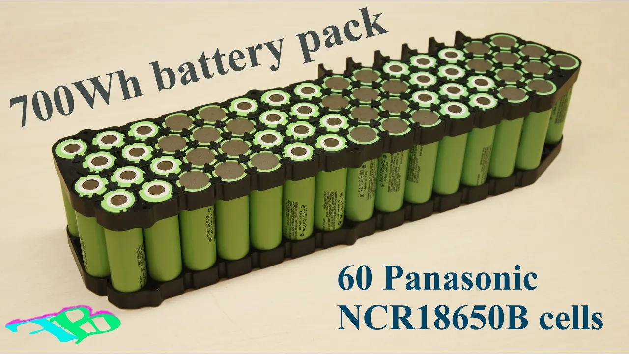
5) Adding the BMS:- Once we have all of your parallel groups connected in series, you have a battery pack. The cell on one end of the chain will have a negative cell with nothing attached to it. That is our main battery negative. On the other end of the series chain, you will find a cell that has a positive end that nothing is connected to. That is your main battery positive.
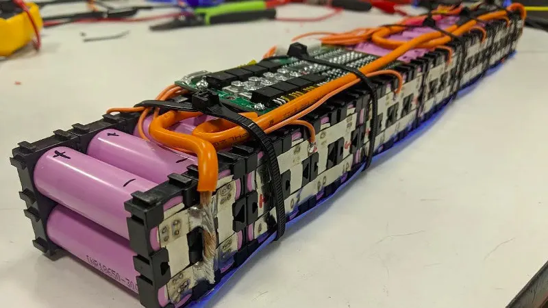
While our battery is now technically ready to use, if we don’t have any form of over-current or over-charge protection, a battery can be dangerous. If something goes wrong with our battery, load, charger, or even a wire, you could be in for some serious trouble.
This is why a BMS is essential. A BMS, or Battery Management System, is a small circuit board that converts several dangerous, fairly useless lithium ion cells into one safe, useful, battery pack. A BMS has several roles, and some more expensive BMS boards do more than others.
Function of BMS:-
- Overcharge Protection:- A BMS Monitors the voltage of all cell groups. When any one of those cell groups reaches 3.3V, charging is stopped. This prevents your cells from being damaged from being overcharged, and also helps prevent fires.
- Cell balancing:- If one or more of your cell groups are at a higher voltage than the others, a BMS uses a circuit and small balance resistors to lower the voltage of any high cells.
- Over Discharge Protection:- A BMS disables the battery pack when any cell's voltage falls below a certain threshold. Remember, if a cell goes much lower than that, it will get damaged.
- Overcurrent protection:- Another critical job of a BMS is to make sure the battery pack is not put under too much stress. So, every BMS has a maximum current that, if achieved, will turn the battery pack off. Over-current protection applies to both charging and discharging the battery pack.
- Short Circuit protection:- A short circuit is equivalent to a 0 Ohm load. Ohm’s law states that the amount of current that will flow through a given circuit is a function of, among other things, the circuit’s resistance and voltage. When a short circuit condition is created, the only resistance to the flow of current will be the very low resistance of the conductor (wire or nickel) and cell itself.
6) Enclosing the battery pack in an IP 65 Enclosure:- the battery pack must be enclosed with such material so that the it protect the all around exposed nickel strip from getting any accidental shorting.
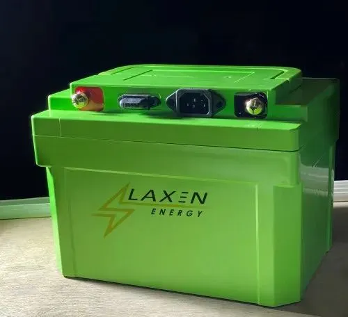
This completes the designing of a battery pack successfully.