Week -2
Task 1 :- To make a simulink model of Door bell using solenoid block.
Blocks used:- Pulse Generator, Electrical Switch, Battery, Solenoid Block, Linear Translation Sensor, Electrical Reference, Linera Translational Reference, Solver Configuration, Simulink- PS Converter, PS- Simulink Converter, Scope
Working of Model:-
Pulse Generator is given duration of operation 5 secs, Pulse width is set accordingly to turn ON the bell for 2sec and set as 40% of total pulse duration, A delay of 2 sec is provided to turn on the pulse. A simulink- PS converter is then used to convert the simulink signal into Physical signal, and that physical signal is fed through the Electrical Switch for ON/OFF operation of the switch. Battery Source of 12V DC is connected along with the switch and in series with the battery a Solenoid Coil is connected. Solenoid Block is having two parts that are electrical and mechanical, Electrical part is connected to the battery source and mechanical part i.e. C is connected to Linear Translational reference and R is connected to Translational sensor to detect the change of position and velocity of Plunger of That Coil. Then the signal at the output of Sensor i.e. P (position of plunger) and V (velocity of plunger) are converted back to Simulink signal through PS-Simulink Converter and Then they are displayed through Scope. Also solver configuration is connected so as to specify the solver parameter that are required to begin the simulation of the model.
Observation from the model :-
When the pulses are generated from Pulse Generator block for the specified delay and specified period of time the electrical switch get a physical signal to turn the switch into ON condition and when the switch turn ON The circuit become close and the electric current flows in the circuit, which result in flow of current through solenoid too and when current passes through the solenoid due to the electromagnetic properties of current it will move the plunger accordingly and we can observe the position of plunger in the scope and when the plunger moves it will be striking the gong of the bell resulting in creation of sound. This process of excitation and movement of plunger will result in sound creation through bell.
Model Url- https://drive.google.com/file/d/1NAgeaBFx9aIFqMzWOfRihy9Dw2EJ7NRt/view?usp=sharing
Results:-
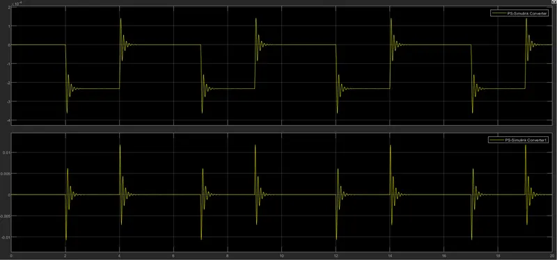
where PS simulink conv.1 displays the position and PS Simulink conv.2 displays the velocity of Plunger
Task 2:- Using a Thermistor to sense the temperature of a heater and turn on and turn off the fan as per the condition specified.
Block Used:- Pulse Generator block, Sum, Scope, Simulink-PS Converter, Controlled Temperature Source, Thermal Refrence, Thermistor, Battery, Current Sensor, Electrical Reference, Solver Configuration, Switch, Constant, Controlled voltage Source, DC Motor Block, Mechanical Rotational Reference, Ideal Rotational Motion Sensor, PS-Simulink Convertor, Scope.
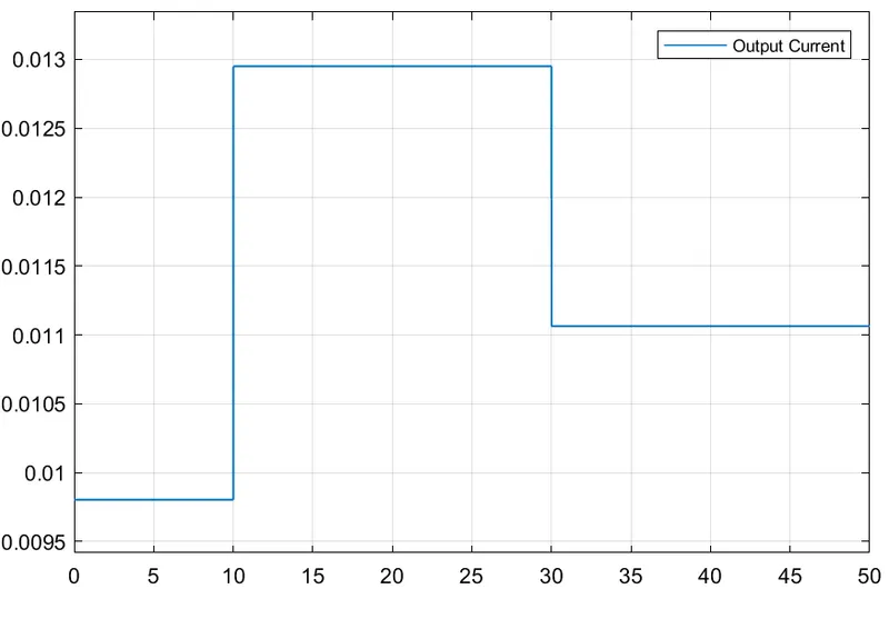
Working Of the Model:- In this challenge i have used three different Pulse Generating block which will be having an Amplitude same as the value of Temperature given i.e.(273+x) where x will be the temperature generated for diffrent time as stated in the challenge. Also a delay of 10sec and 30 sec is provided to Pulse Generator block1 and 2 respectively, Pulse width is adjudted such that it operates for that much duration as mentioned is challenge afterthat the output of three Pulse Genrator are added to a sum block and scope has been used to check whether the input signal is given correctly or not. After the input signals are upto the mark then i have connected it through a connection S of Controlled temperature source by using Simulink-PS converter in between and Input A of themp. source is connected to thermal refrence and Connection B is connected to T of thermistor block also i have connected a 12V battery as electrical source and a Current sensor to detect any change in the value of Current flowing through the circuit, also an electrical refrence has been provided to the electrical circuit. Now afterthat i have to monitor that what is the amount of current flowing in the circuit so i used a Scope to view that through PS-Simulink converter and when i got the amount of current which will flow when temperature of the room is 25 deg C by changing the amplitude of any one of the Pulse Generator to 273+25 the current comes to be around 0.012A. So I gave this input as a threshold to the switch to turn it ON only after that value, Also i have used 2 constant 0 and 1 as as input to the switch. Now this signal is simulink signal and we need to run a Dc motor so the signal need to be changed again to Physical signal to Simulink-PS Conv. and this Physical signal is now fed as an input to a Controlled Voltage Source and then the DC motor is connected to the same voltage source as the electrical connection requires a refrence so an Electrical reference is provided to the circuit. And since the signal has been converted twice into physical signal so another Solver Configuration is required and provided. Now the mechanical part of the Dc motor is to be connected. I connected C connection of Motor to a Rotational Mechanical refrence and R connection is connected with the Ideal Rotational sensor to monitor change in the anuglar Velocity of the motor. Now the output block of sensor contain W which is angular velocity and A angle of rotation. These outputs are connected to a scope through a PS- Simulink Converter in between and Model was run to check its working.
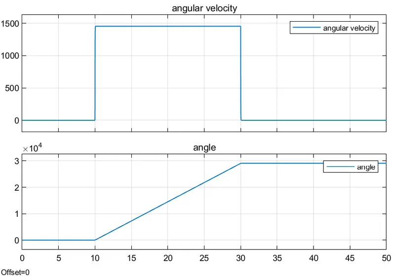
Observation:- When the input Pulses was given through Pulse Generator block there result where displayed in the scope. And when these input are given through a controlled temeperature source and then through thermistor we have to check for what value of current will be there in the circuit when the temperature is 25 deg C of the room. So by changing any of the pulse Generator Amplitude to 273+25 we get the value of current which we will required to turn on the switch i.e. 0.012A and the value of current for 20, 27 and 23 deg C are less than 0.01, less than 0.013 and more than 0.011 respectively. So the threshold value of switch is changed to 0.012 and then the signal is applied through controlled voltage source and DC motor. Now the Dc motor will ony run when the input signal of Current will be greater than 0.012A otherwise it will remain Off. this can be seen in the Scope1 that the motor is having an angular velocity only between the duration 10 to 30 sec when the temperature of the room is above 25 deg C i.e. 27 while it will remain in OFF condition.
Model Url- https://drive.google.com/file/d/1oCu9pazcLvGPqSIrhggQdfgzvj-CX9u7/view?usp=sharing
Results:-