Week-11 Challenge: Braking
Challenge URL- https://drive.google.com/drive/folders/1Lyf8V3haT-hBS_-KCQmCRbGFZF_JSDGc?usp=sharing
Task-1 For a defined Drive cycle calculate enerfy required for breaking.
Solution:-
I have made a drive cycle in MS Excel and plotted it with the time. I have considered time of 120 sec and motor speed is assigned to it in km/hr. I have also converted that speed in km/hr to m/sec.
The drive ccyle plot can be seen below with speed in m/s at Y axis and time in seconds at X axis
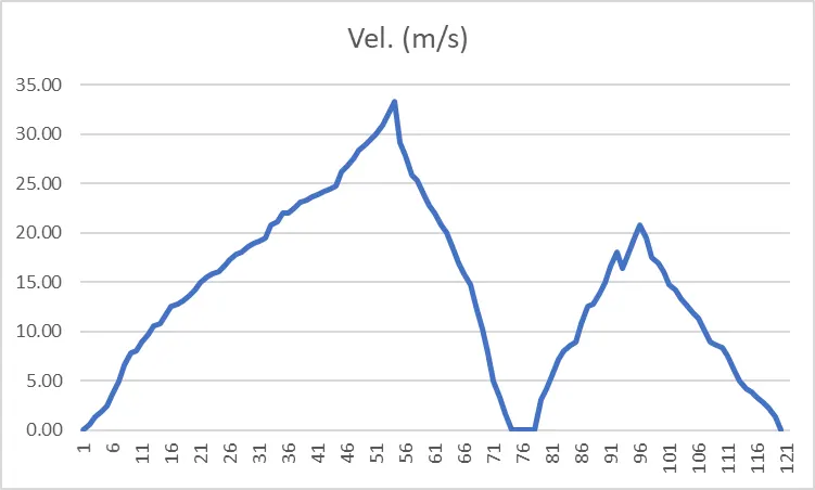
From the above plot we observe that the braking is happening two times during the driving
So we must calculate the braking energy and braking power at these two points.
As we know that the braking energy as an expression of Kinetic energy and is expressed as:-
Ebrak= 1/2*m*((vf-vi)^2)
where m is the mass of the vehicle
vf is the final velocity in m/s
vi is the initial velocity in m/s
In our case let us consider the mass of the vehicle is 1000 Kg.
Applying Kinetic energy formula in the table below and finding the braking energy and power
| Initial Speed (m/s) | Final Speed (m/s) | Difference in Velocity | Time in Seconds | Braking Energy (J) | Braking Power( Kw) |
| 33.3 | 0 | 33.3 | 20 | 554445 | 27.722 |
| 21.66 | 0 | 20.83 | 24 | 216944.5 | 9.04 |
So total braking energy required by the vehicle to complete the defined drive cycle will be addition of both the braking energy and will be 771389 J.
Task-2 Electric Motor can't develop high torque as on starting and how brakes are cordinated in an electric vehicle
Solution:- This could be understood by understanding the Torque- Speed charterstic of both DC motor
From the above plot we can see that the dc motor operates in two diferent region that are Constant Torque and Constant power region. During starting of the motor it attains peak torque till it reaches upto a certain level which is wrated in image and is known as critical speed. When motor reaches above its critical speed torque produced by the motor decreases and the power drawn by the motor become constant.
Since the torque produced in the constant power region is low so it is not possible to develop high braking torque in this region.
Cordination of Electrical and Mechanical Brakes:-
Electrical Braking:- Torque is produced by the winding of the motor to stop the vehicle. Torque is developed during the braking operation. This braking torque opposes the motion of rotating shaft or transmission of the vehicle. This is done by changing the polarity of supply voltages applied to the motor and the motor operates on the speed torque characerstic depending upon the method of braking applied. The electric braking system used in EV or HEV uses Regenrative braking in this mode the motor work as a generator during braking and produces a retarding torque which halts the running motor. The kinetic and potenial energy, minus the losses of the motor are fed back to the battery and the battery is charged during the braking.
Mechanical Braking:- In this type of braking, the frictional force between the rotating parts and the brake drum produces the required braking. This braking is usually discharged in the form of heat. Mechanical equiment such as Brake linning and brake drum are required. Whether it is electrical or mechanical braking of the drive must stop the vehicle at a specified time of point of time and position.
Braking strategies:-
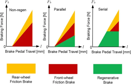
Series Braking:- In this type of control strategy mechanical and electrical brakkes are applied one after the another. We can apply one brake at a time either mechaical or Regenrative Braking.
It can be further classified keeping in view the below factors:0-
a) Comfort of the passenger
b) Braking according to the energy efficiency
Parallel Braking:- In this tyoe of braking system both mechanical and electrical brakes are applied simultaneously.
Task- 3 To develop a MATLAB program and plot the contour of Speed, Torque and Efficiency
Since we know that the eficiency of the motor is calculated by the ratio of output power delivered by the input power withdrawn by the motor.
The losses accociated withthe motor are Copper losses, Iron Losses, Windage losses and the constant losses which are there in the motor. So considering all those losses and adding up them with the Output power we will get the Input Power.
Also we know that the power generated by th emotor is the product of Torque and angular velocity of the motor so with this expression we can calculate the output power of the motor.
MATLAB Script:- MATLAB program of the same is written in as follows:-
clear all
close all
clc
W= linspace(1,1000);
T= linspace(1,250);
kc= 0.18; %Copper loss const.
ki= 0.006; %Iron loss const.
kw= 0.000015; %windage loss const.
c= 20;%Constant Losses
[X,Y]=meshgrid(W,T);
Pcu= (Y.^2)*kc;%Copper Loss Power
Pir= X*ki;%Iron Loss Power
Pw= (X.^3)*kw;%windage Loss power
Pout= X.*Y;%Output Power
Pin= Pout+Pcu+Pir+Pw+c;%Input Power
Eff= Pout./Pin;
n= linspace(0.7,0.95,10);
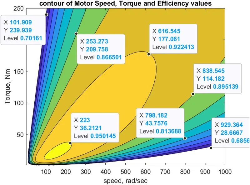
contourf(X,Y,Eff,n);
xlabel('speed, rad/sec');
ylabel('Torque, Nm');
title('contour of Motor Speed, Torque and Efficiency values');
Result:- The reult of the script file is displayed below