Project-1: Modelling an electric Car with Li-ion battery
Task:-
Create a MATLAB model of electric car which uses lithium ion battery and suitable motor. Choose suitable blocks from Simscape or Powertrain block set. Implement the vehicle speed control using PI controller and generate brake and accelerator commands. Avoid using readymade driver block for speed control.
Prepare a report about your model including following:
Objectives, System level configurations, Model parameters, Results, Conclusion.
Answer:-
Project URL:- https://drive.google.com/drive/folders/1ULxMmDowznSuLpSLElBWNIwVFo40uMd_?usp=sharing
An electric vehicle, such as an electric car, uses one or more electric motors powered by a battery pack to accelerate and drive. Depending on the type of EV, the electric motor(s) either assist a conventional internal combustion engine (ICE) or power the car completely.
When talking about EVs, we generally refer to three main types of electric vehicles: hybrid electric vehicles (HEV), plug-in hybrid electric vehicles (PHEV) and battery electric vehicles (BEV).
i) Hybrid Electric Vehicle:- A hybrid electric vehicle (HEV) combines a conventional internal combustion engine (ICE) with an electric motor and battery pack to reduce fuel consumption. HEVs achieve this by using an electric motor to drive the car during conditions when an ICE is especially inefficient, like when accelerating from a stop. Hybrids can also favour the ICE unit when it is more efficient to do so, such as cruising at highway speeds.
Hybrid vehicles are most similar to drive to normal ICE vehicles, as owners can only top them up with traditional fuels (usually petrol). HEV technology automatically charges the battery through what’s known as ‘regenerative braking’ and activates the electric motor system when conditions are suitable, meaning drivers do not have to monitor charge or plug the cars into power outlets.
Toyota RAV4 Hybrid, Australia's most popular hybrid vehicle
ii) Plug In Hybrid Electric Vehicle (PHEV):- A plug-in hybrid electric vehicle (PHEV) combines an ICE with an electric motor and battery pack similarly to a hybrid, however comes with distinct differences. PHEVs generally have larger battery packs and more powerful electric motors than hybrids, as the electric system does a lot of the heavy lifting while driving. This means PHEVs can be driven in electric-only mode, switching the ICE off entirely.
Driving a plug-in hybrid is similar to driving a hybrid, as the car will automatically recharge the battery and switch between ICE and electric power based on conditions. However, drivers have the choice of topping up PHEVs with both fuel and electricity. A PHEV can run on just petrol if all battery charge is used up, and battery charge alone if all fuel is used up.
Mitsubishi Outlander PHEV GSR plug-in hybrid electric vehicle
iii) Battery Electric Vehicle (BEV):- A battery electric vehicle (BEV) is considered to be an ‘all-electric’ or ‘full-electric’ car. BEVs are powered exclusively by electricity, with their electric motors drawing current from onboard battery packs. BEVs do not have any form of ICE.
Given that BEVs rely solely on electricity, they tend to have much larger capacity batteries and kilowatt-hour (kWh) outputs than comparable hybrid and plug-in hybrid electric vehicles. This extra battery tech typically results in BEVs costing more than other types of EVs. BEVs need charge to be driven. This can be done through either a home charger or fast charging station, or energy recouped by regenerative braking.
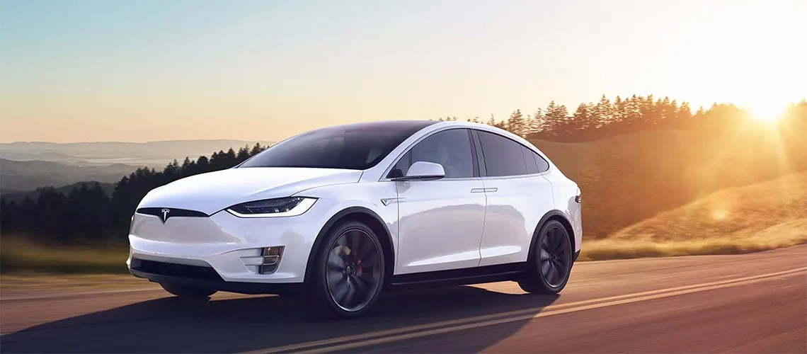
Tesla Model X battery electric vehicle
Electric Vehicle Model:-
Blocks used:- Drive Cycle Source, Switch, Goto, From, Integrator, PowerGui, Sum, Product, Derivative, Delay, Saturation block, Controlled Voltage Source, Controlled PWM source, H Bridge, DC Motor, Solver Configuration, Electrical Reference, Current Sensor, Mechanical Rotational Reference, Controlled Current Source, Battery, Simple Gear, Inertia, Vehicle Body, Tire (Magic Formula), PS constant, PS Terminator, Gain, Display and constant.
Block Diagram of Electric Vehicle:-
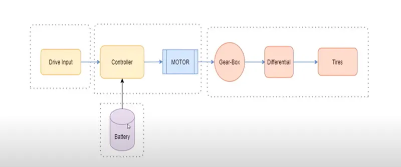
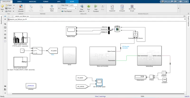
The Electric vehicle model is made using MATLAB/Simulink. This model is a complete representation of an Electric vehicle which is built using Powertrain blocksets. The major subsytem of this model are as follows:-
i) Drive Cycle Source
ii) Driver
iii) Motor and Controller
iv) Battery
v) Vehicle Dynamics (Vehicle Body).
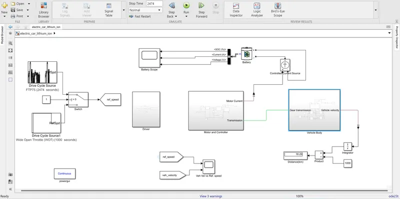
Let us see these subsytem in details:-
1) Drive Cycle Source:- Here in this project i have used two Drive cycle source which are FTP-75 and Wide Open throttle (WOT). Also i have used switch in between the two drive cycle source so that at one time only one source is applicable to the model. Constant value 0 and 1 is used to change over between the Drive cycle source. With constant value 1 FTP 75 drive cycle is selected and with 0 WOT.
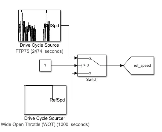
- a) FTP-75 (2474 Cycle) :- Fedral Test Procedure 75 drive cycle is used to estimate the range distance travelled by an Electric Vehicle in a single charge.
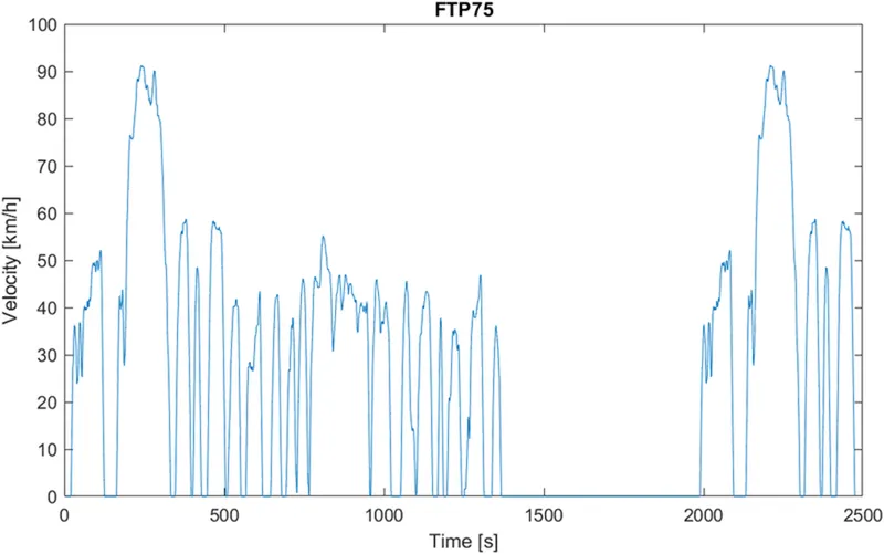
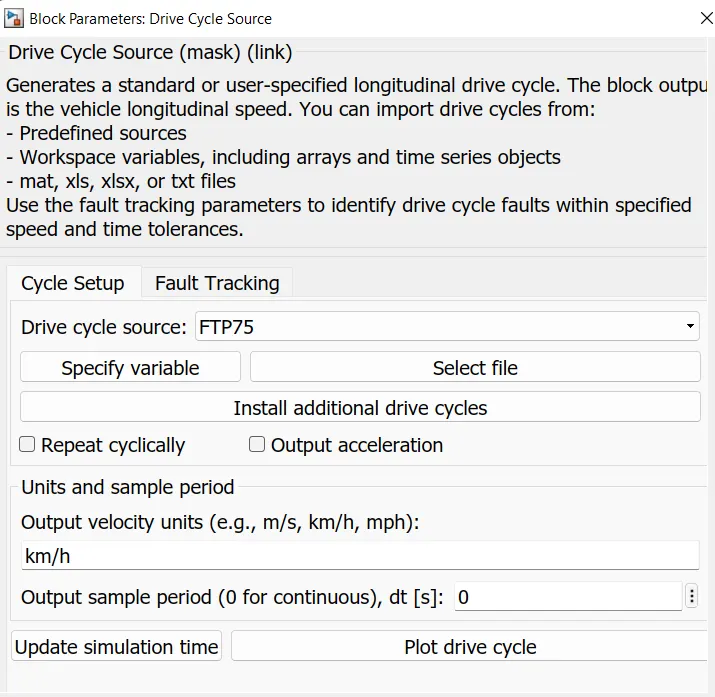
Here the model simulation or run time will be 2474 sec as per the standard.
- b) WOT (Wide Open Throttle) :- It is used to generate the user specific or longitudnal drive cycle. The block output is the vehcile longitudnal speed. Here in my case I have declared parameter of WOT as :-
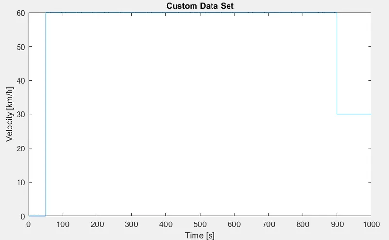
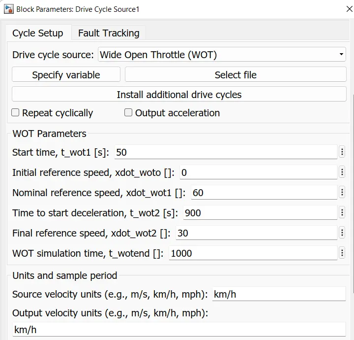
Here the model is simulated for 1000 sec.
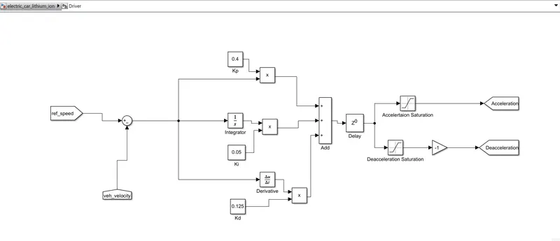
2) Driver:- For the modelling purpose PID and PI are widely used for speed control. While Modeeling an Electric Vehicle we are having a reference speed whixh is generated from the drive cycle input. After the completition of the simulation process we have to check whether the actual vehicle velocity matches the refrence speed or not.
A PID controller typically works on the principle of adjusting or tuning the proportional, integral, or derivative terms. The difference between these variables is evaluated and part of the input signal is fed back to the device as a feedback control signal. This value is generally known as the correction factor.
a) Proportional Tuning:- This type of tuning involves adjusting or correcting the desired signal proportional to the current error signal e(t). The error signal is the difference between the setpoint or the target value and the actual value. The current error signal is further multiplied with the pre-calculated proportional constant to obtain the output. If the error value is equal to zero, the controller output value is also zero.
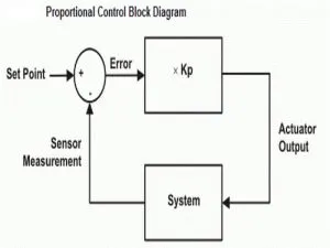
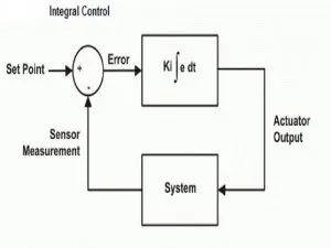
b) Integral tuning:- I-controllers make use of integral tuning to generate the output signal to manipulate various physical parameters. This type of tuning tends to integrate the error signal with respect to time until a minimum or zero value of the error is achieved. In case of a negative error value, the integral control tends to decrease the output. The speed of response and the stability of the system; however, get affected during the process.
The integral gain of the ‘I’ controllers, usually denoted by Ki, is indirectly proportional to the speed of response of the system. This means that if the integral gain is increased, the speed of response of the system gets reduced by a comparable value. Similarly, the integral gain is directly proportional to the steady-state error. This means that the steady-state error gets reduced by reducing the integral gain of the controller and vice versa.
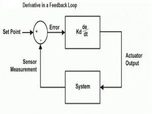
c) Derivative Tuning:- The ‘D’ controllers or derivative tuning is normally used to overcome certain limitations of the ‘I’ tuning. For instance, an ‘I’ controller does not have the ability to predict the future behaviour of the error value. The output of the derivative controllers is equal to the rate of change of the error signal with respect to time multiplied by the derivative constant. The derivative tuning helps in improving the system response and decreasing the settling time of the output. The derivative gain Kd is directly proportional to the responding speed of the system. This means that an increase in the derivative gain of the controller tends to increase the response time of the system.
I made a PID controller in the simulink with the help of constant which describe the value of Kp, Ki and Kd and the integrator block for Integral control and derivative block for derivative control of the controller and the values of the gains come out to be Kp= 0.4, Ki= 0.05 and Kd= 0.125
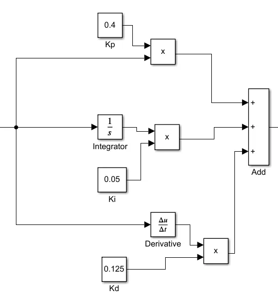
This PID controller gets the input in the form of error signal which is generated as a result of negative feedback. When the reference speed and Actual vehicle velocity is compared there diffrence is the error signal. This error signal is applied to the PID controller and the output of the PID controller is sum of all the three controls which then fed through the Delay block which is of zero order and it carry out all the algebraic computation. And after the delay blcok the Saturation block (for providing upper and lower limits) are there for respective Acceleration and deacceleartion commands and these commands are then fed to the Power converters.
3) Motor and Controller:- This subsystem contain blocks like Controlled voltage and PWM source, H bridge and Dc motor lets see them one by one:-
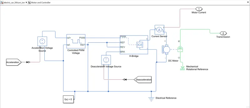
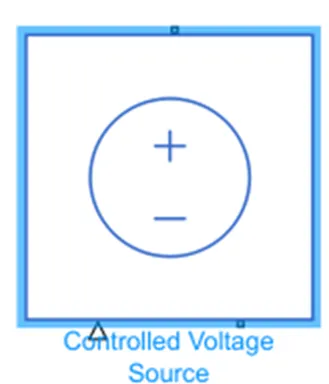
a) Controlled Voltage Source:- It is a souce which activate when the signal applied to it get high and the volatge is applied across the +ve terminal of the Source and in this model i have used two voltage sources one for acceleration and another for braking.
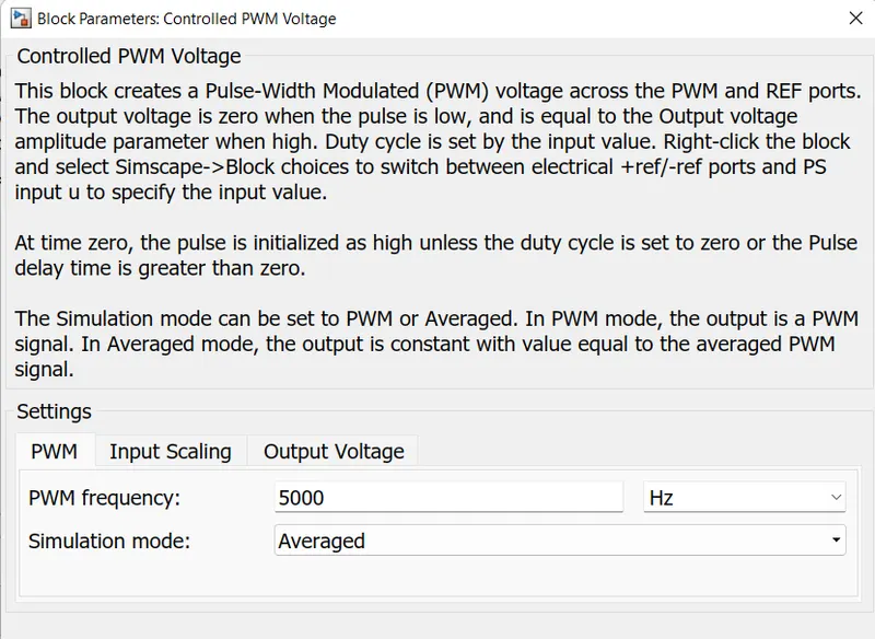
b) Controlled PWM Voltage Source:- It is used to provide controlled Pulse widdth modulated signals to the H bridge. The block will provide output from the PWM and reference is used as ground by connecting it through electrical reference. The input of the PWM block is +ve and -ve reference. +ve reference is provided from the Accelerated Control Voltage Source and -ve of the ref is connected to the Electrical reference.
Parmeters of the PWM block are as follows:-
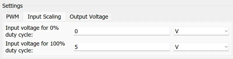

c) H Bridge:- H bridge is the power converter used here as it convert the required signal in the form of desired output and the output is applied to the Dc motor. It has two part one is left and other is right part. Right part is connected to the positive and negative of dc motor. and The left part consist of following parameters:-
PWM-(Pulse width Modulation) will provide the voltage pulses to the H bridge either in PWM or average form. and is applied input from PWM of the Controlled PWM Voltage Source
Ref- (Reference)- Electrical Reference is provided to this port.
Rev- (Reverse)- Electrical reference is provided to this port.
Brk- (brake)- It is provided signal from the Brake controlled Voltage source
Block parameters of H bridge are as follows:-
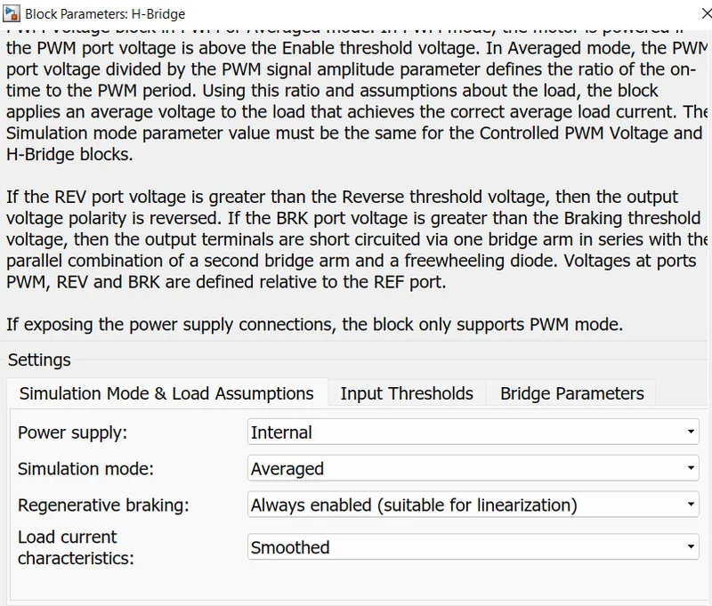
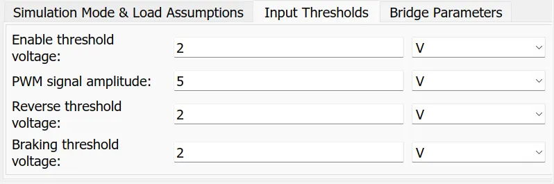
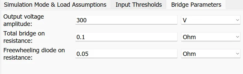
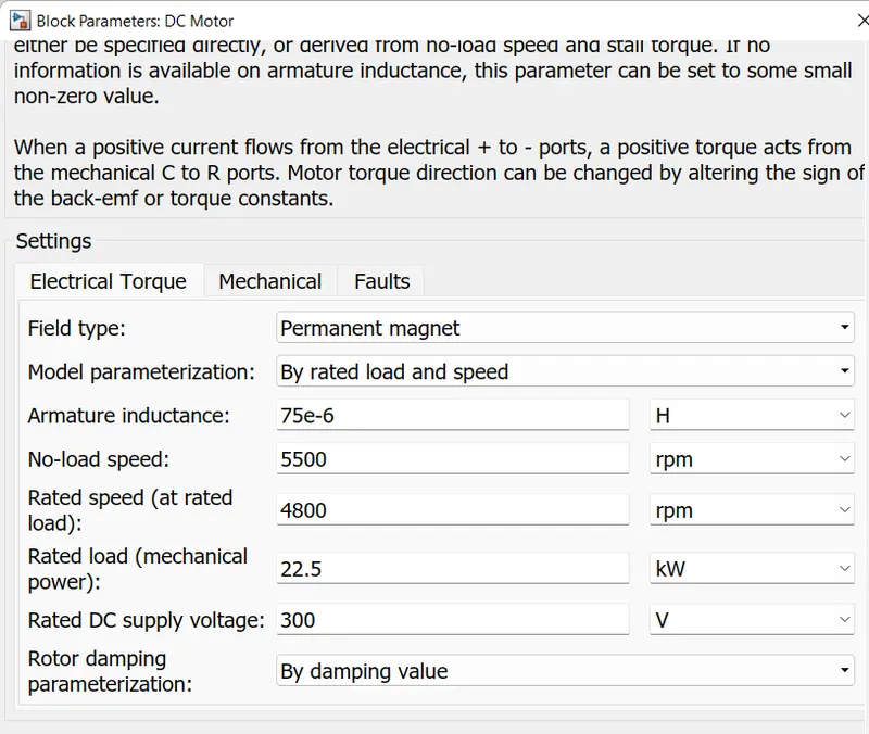
d) DC Motor:- Simple Permanent Magnet Brush type Dc motor is selected as they are easy to model because of there less complex behaviour as in comparison with induction motor or BLDC motor.
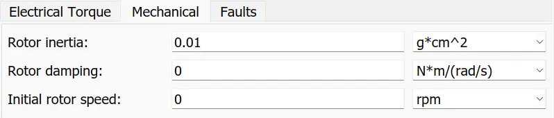
This motor has two part one is electrical on the left and other is mechanical part on the right. Mechanicla part is having two connection R ( Rotor) and C (Case). C part is connected to the rotational reference and R is connected to the Base of Simple gear of the vehicle body subsystem. Electrical part comprises of positive and negative terminals. The positive part is connected to the H brige positive and negative terminal ios connected to the negative of H bridge along with the electrical reference.
Block parameter of Dc motor are as follows:-

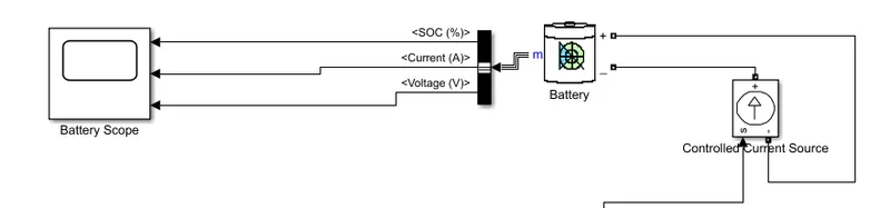
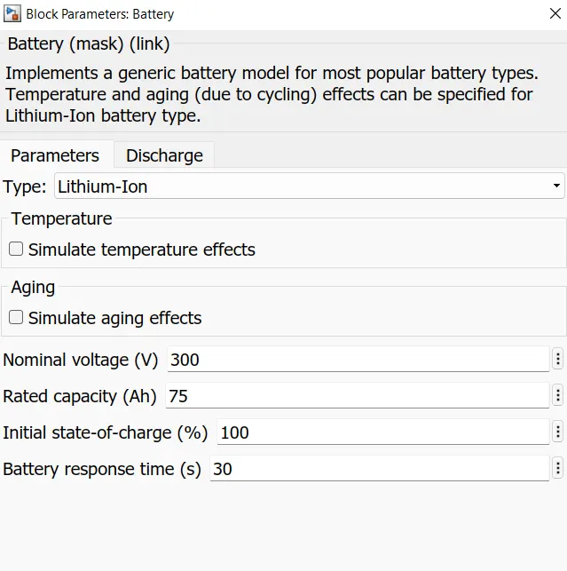
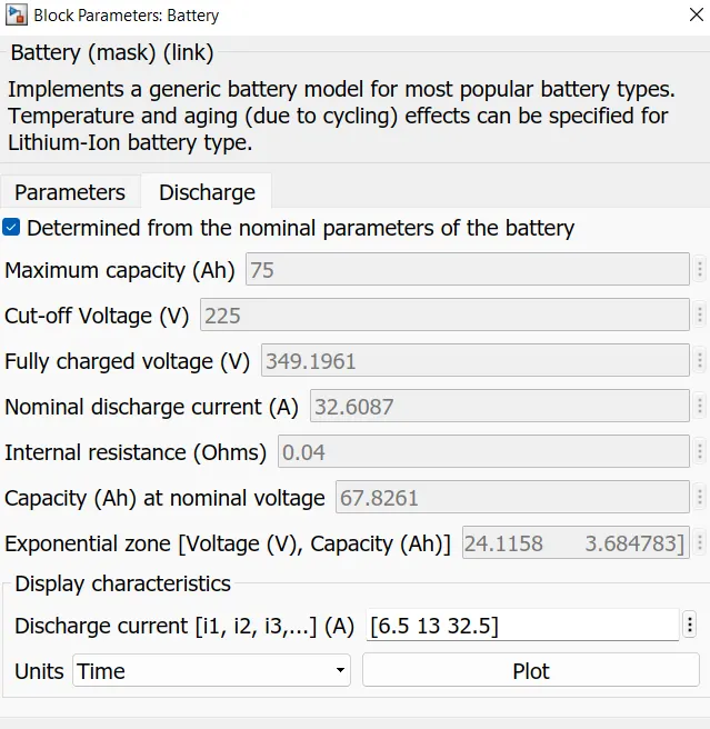
4) Battery:- A battery package is used which is Lithium Ion Battery of 300 V and 75 Ah. The output of the battery is SOC, currenta and voltage. A controlled current source is used to charge and discharge the battery. The input of the Controlled current source is from the Power converter block through a PS- simulink converter.
Block parameter of the Battery are as follows:-
5) Vehicle Dynamics (Body):- This subsystem contain major block such as Simple Gear, Vehicle Body and Tire ( magic formula). It focuses more on the dynamics of the vehicle like the road condition, sourrounding condition and the load on the wheels etc.
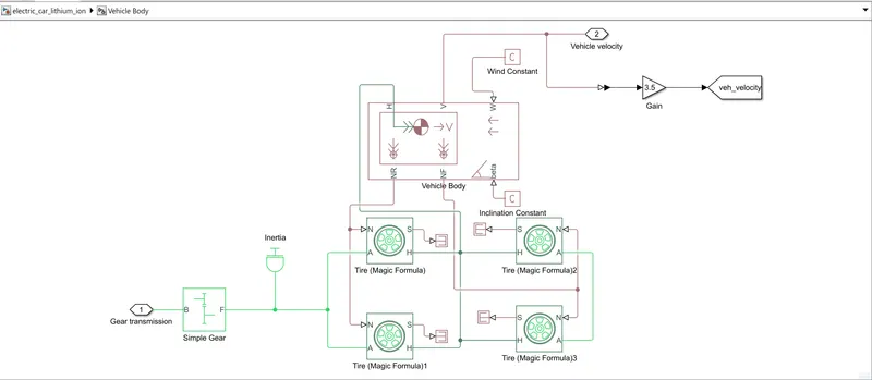
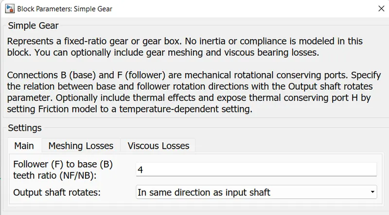
a) Simple Gear :- It is used for the transmission system of the vehicle. I have used simple gear to simplify the transmission related parameter. It has B which is base and it is getting input from the motor shaft and follower which is reducing the speed of motor and is coupled to the axle of the rear wheels.
Block parameter of the Simple Gear are as foolows:-
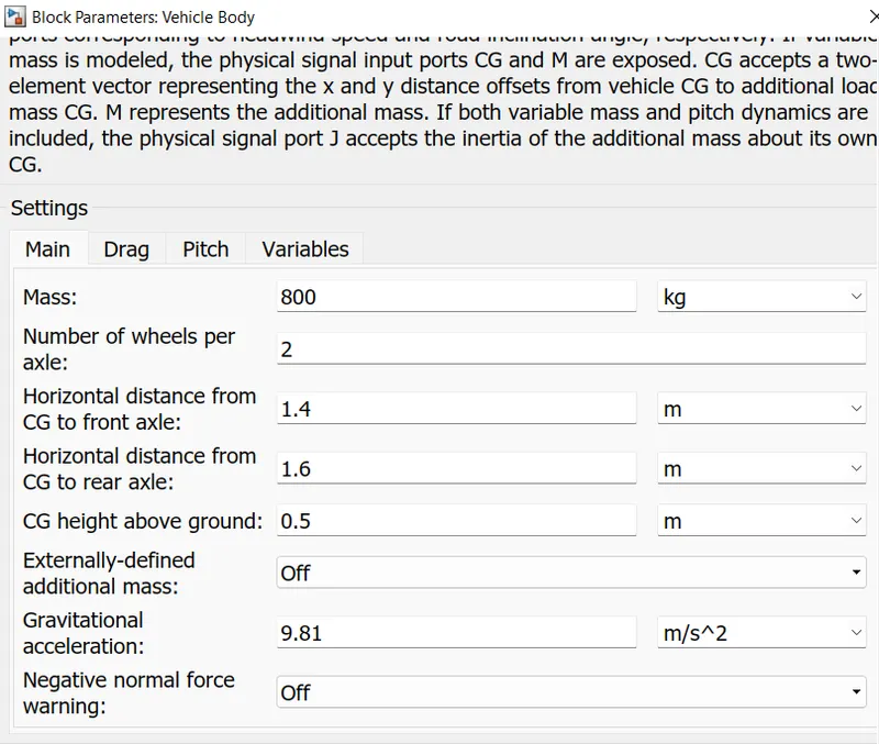
b)Vehicle Body:- The vehicle body block contain six main sub-parts such as:-
H (Hub) - It is used to connect the hub of the wheels to the main body of the vehicle
V (Velocity)- It is an output port and used to tell us that at what speed our vehicle is running i.e. the actual speed of the vehicle is known through this port.
W (Wind Velocity) - It is an input port by which we can consider the impact of wind acting on the vehicle.
NR (Normal Rear Force)- It gives the signal output for normal force acting on the rear wheel of the vehicle
NF (Normal Front Force)- It gives the signal output for normal force acting on the front wheel of the vehicle
Beta (Angle of Inclination)- It is used to consider the hill climbing force acting on the vehicle.
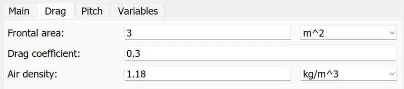
Parmeter of Vehicle body are as follows:-
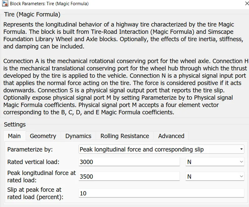
c)Tire (Magic Formula):- Here i have used Magic formula tire in this model, as it allow us to model the tire behaviour on highways. It also allow us to consider tire inertia, stiffness which can be more accurate for real world condition.
Parameter of Tire block:-



Results:-
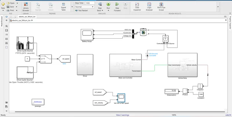
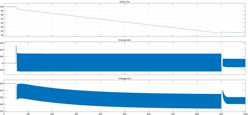
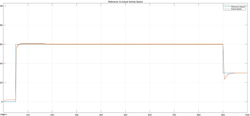
i) WOT:- For the input drive cycle of Wide Open throttle the distance travelled by the vehicle is 15.43 km and the simulation is run for total 1000 seconds. Vehicle start after 50seconds and then tries to attain speed of 60 kmph till 900 sec and after 900 sec the deaccelration starts and vehicle starts to deaccelerates to 30 kmph at the end of 1000 sec.
The Battery SOC after the test is around 93.5 % and this can be seen below:-
Vehicle is foloowing the refrence velocity for the WOT test.
ii) FTP 75 (2474 sec) :- The simulation run time foe this drive cycle is about 2474 seconds. The distance travelled by the vehicle is about 18.29 km.
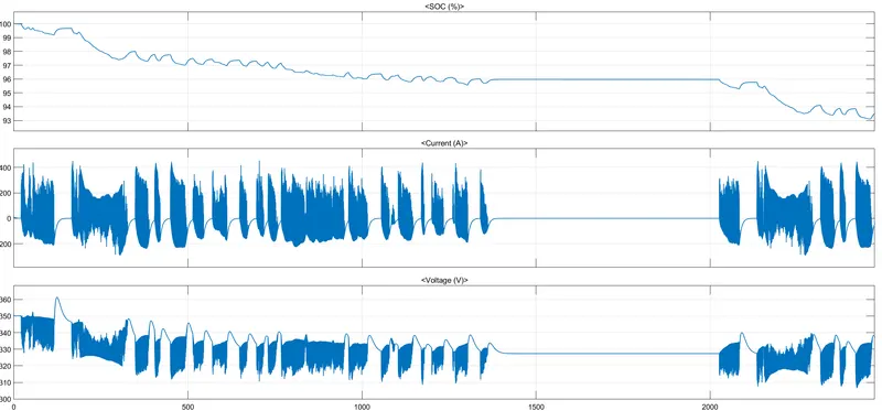
Battery SOC is about 94.5% after the test.
Vehicle velocity is actually following the reference velocity.
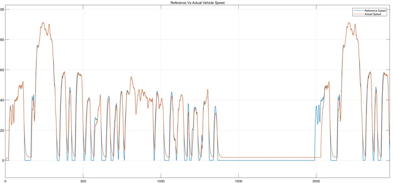
Conclusion:- The main objective of the project was to make PID controller which is able to track the reference speed and act accordingly to achieve the same with minimum possible error. Here i have avoided ready made PID controller block and made my own PID controller with constant which states the value of gain and Integrator and Derivative for the respective Integral and Derivative control. From the result we can conclude that the main objective of the controller is achieved and the vehicle ois following the reference speed.