Final Project: Design of an Electric Vehicle
Aim :- To create a MATLAB model of electric car containing DC motor and battery.
Block Diagram:-
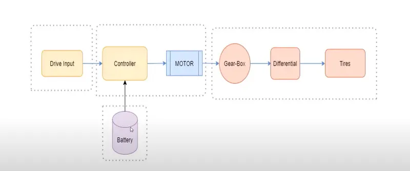
Electric Vehicle have a forward and reverse mode. When we place the vehicle in gear and press on the accelerator pedal the following things happen:
- Power is converted from the DC battery to AC for the electric motor
- The accelerator pedal sends a signal to the controller which adjusts the vehicle's speed by changing the frequency of the AC power from the inverter to the motor
- The motor connects and turns the wheels through a cog
- When the brakes are pressed or the car is decelerating, the motor becomes an alternator and produces power, which is sent back to the battery.
Model URL:- https://drive.google.com/file/d/1ddRCghYngWdhIgLmCBn1PWyeu3vldEOD/view?usp=sharing
Simulink Model:-
Block Used:- Drive Cycle Source, Multiport Switch, constant, Longitudnal driver, Simulink- PS converter, PS- Simulink Converter, Controlled Voltage Source, Controlled PWM Voltage Source, H Bridge, DC Motor, Current sensor, Electrical Reference, Solver Configuration, Rotational Reference, Mechanical Rotational Sensor, Scope, Simple Gear, Tire, Vehicle Body, PS terminator, PS constant, Battery, Controlled Current source, Scope, Intergrator, Gain, Add, saturation block, Product and Display.
I have used three different drive cycle sources :-
i) FTP 75 (2474sec)
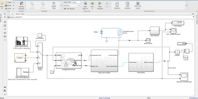
ii) Artemis Motor 150
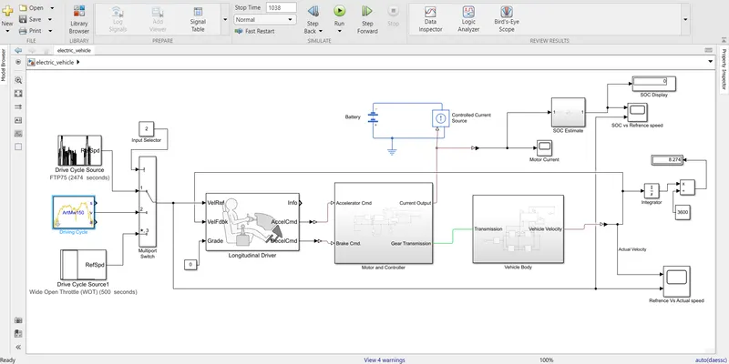
iii) Wide Open throttle.
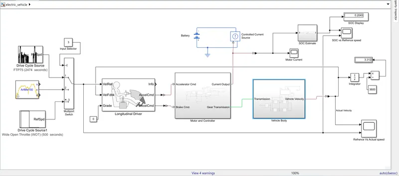
System Level Configurations :-
There are several main components which needs to be present in an electric vehicle these aere as folows:-
i) Vehicle Body
ii) Motor
iii) Motor Controller (H bridge)
iv) Controlled PWM Source
v) Battery Bank
vi) Drive Cycle
For the model i have created various subsystem such as Motor and Controller, SOC estimate and Vehicle Body
Let us discuss those subsystem one by one, starting with the vehicle body
Vehicle Body Subsystem:-
Components under this subsystem are Vehicle body, tire and Simple Gear
Input of the block is coming from the motor actual speed and it is generating output as actual velocity of vehicle. This vehicle velocity is a physical signal so converting it into a simulink signal we have to use PS- simulink converter
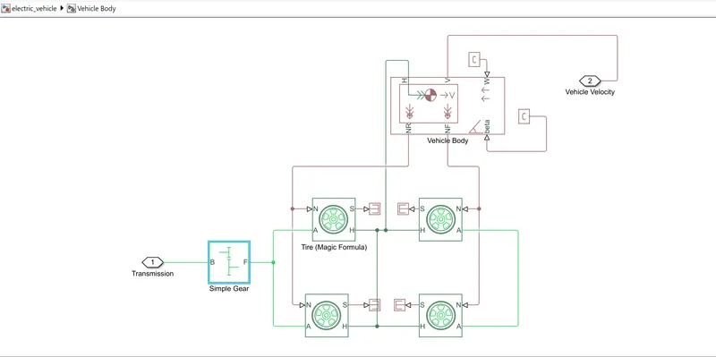
Let us discuss with system level configuration:-
i)Vehicle Body:- We can get the vehicle body block in Simulink as in the image shown below
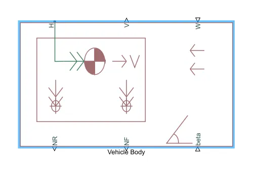
As from the image it was seen that the vehicle body block contain six main sub-parts such as:-
H (Hub) - It is used to connect the hub of the wheels to the main body of the vehicle
V (Velocity)- It is an output port and used to tell us that at what speed our vehicle is running i.e. the actual speed of the vehicle is known through this port.
W (Wind Velocity) - It is an input port by which we can consider the impact of wind acting on the vehicle.
NR (Normal Rear Force)- It gives the signal output for normal force acting on the rear wheel of the vehicle
NF (Normal Front Force)- It gives the signal output for normal force acting on the front wheel of the vehicle
Beta (Angle of Inclination)- It is used to consider the hill climbing force acting on the vehicle.
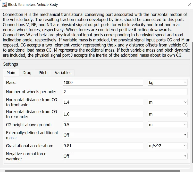
Parmeter of Vehicle body are as follows:-
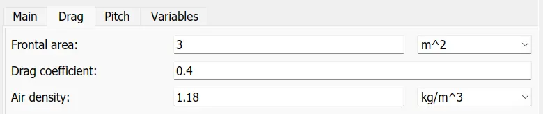
Drag of the vehicle is given as:-
Tire (Magic Formula):-
Here i have used Magic formula tire in this model, as it allow us to model the tire behaviour on highways. It also allow us to consider tire inertia, stiffness which can be more accurate for real world condition. the magic tire block is shown below:-
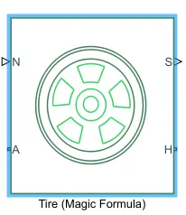
N- (Normal Force)- It stand for normal force and is an input port for the normal forces acting on the tires and is positive in the downward direction.
A- (Axle)- It is mechanical rotational conserving port for wheel axle.
S- (Slip)- It is the physical signal outport and it tell about the slip acting on the tire.
H- (Hub)- It is the mechanical translational conserving port through which the thrust developed by the tires is applied to the vehicle body.
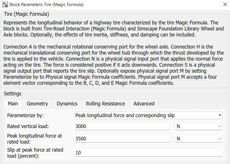
Parameter of Tire block:-

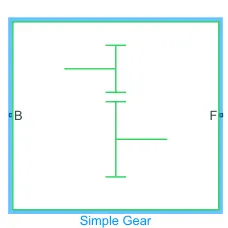
Simple Gear :- It is used for the transmission system of the vehicle. I have used simple gear to simplify the transmission related parameter. It has B which is base and it is getting input from the motor shaft and follower which is reducing the speed of motor and is coupled to the axle of the rear wheels.
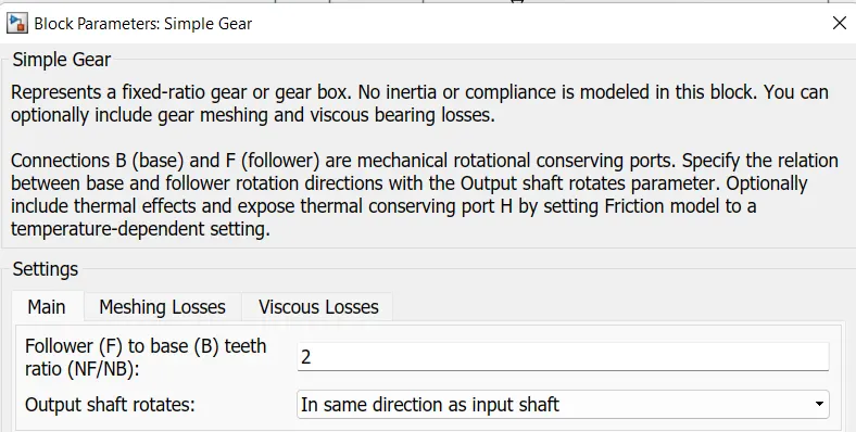
Parameter of Simple Gear:-
Motor and Controller subsystem:-
Motor and controller consisting of DC motor, H-bridge, controlled PWM Voltage, ideal rotational motion sensor, Electrical reference, Rotational Reference, Controlled Voltage source, Current sensor Solver Configuration
It is having input as Acceleration and Deacceleration command which is fed through two different control voltage sourced and DC motor speed is generated as output.
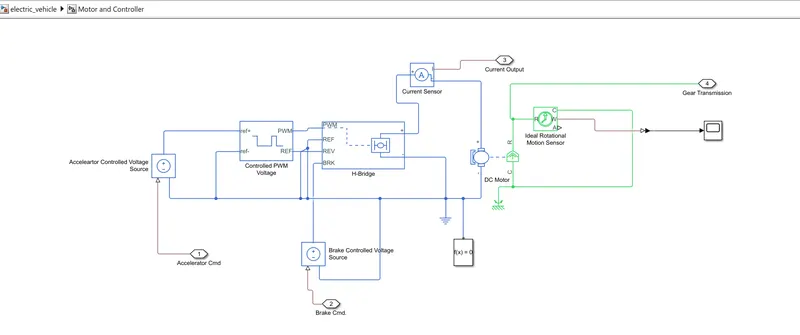
System level Configuration are as follows:-
ii) DC Motor:- Simple Permanent Magnet Brush type Dc motor is selected as they are easy to model because of there less complex behaviour as in comparison with induction motor or BLDC motor.
This motor has two part one is electrical on the left and other is mechanical part on the right. Mechanical part is having two connection R ( Rotor) and C (Case). C part is connected to the rotational reference and R is connected to the Base of Simple gear of the vehicle body subsystem. Electrical part comprises of positive and negative terminals. The positive part is connected to the H bridge positive and negative terminal ios connected to the negative of H bridge along with the electrical reference.
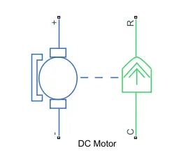
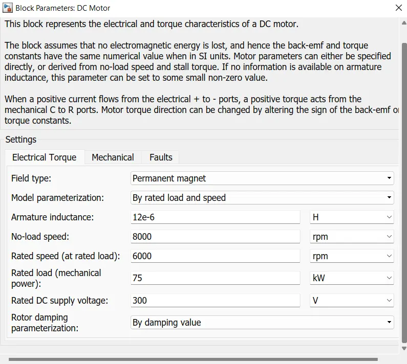
Parameter of the DC motor:-
Mechanical Character:-
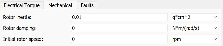
Here the rating of motor i have used is of 75 kW and its rated speed is 6000rpm at 300 V.
iii) H Bridge:- H bridge is the power converter used here as it convert the required signal in the form of desired output and the output is applied to the Dc motor. It has two part one is left and other is right part. Right part is connected to the positive and negative of dc motor. and The left part consist of following parameters:-
PWM-(Pulse width Modulation) will provide the voltage pulses to the H bridge either in PWM or average form. and is applied input from PWM of the Controlled PWM Voltage Source
Ref- (Reference)- Electrical Reference is provided to this port.
Rev- (Reverse)- Electrical reference is provided to this port.
Brk- (brake)- It is provided signal from the Brake controlled Voltage source
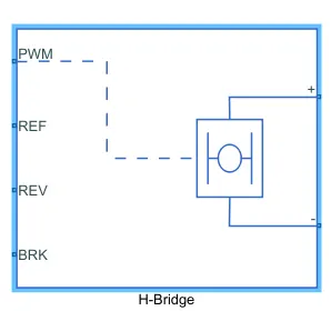
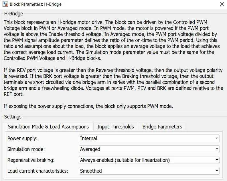
Block parameters are as follows:-
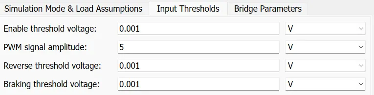
Input Threshold:-
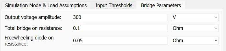
Bridge parameters:-
iv) Controlled PWM Voltage Source:- It is used to provide controlled Pulse width modulated signals to the H bridge. The block will provide output from the PWM and reference is used as ground by connecting it through electrical reference. The input of the PWM block is +ve and -ve reference. +ve reference is provided from the Accelerated Control Voltage Source and -ve of the ref is connected to the Electrical reference.
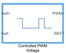
Parameter of the block are as follows:-
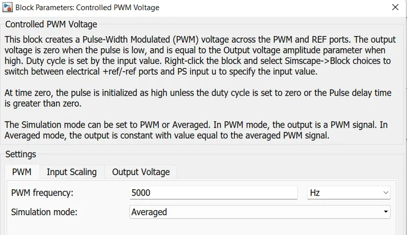
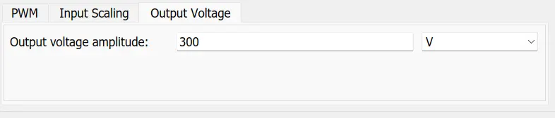
Input Scaling:-

Output Scaling:-
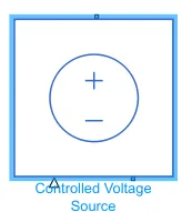
Controlled Voltage Source:- It is a source which activate when the signal applied to it get high and the voltage is applied across the +ve terminal of the Source and in this model i have used two voltage sources one for acceleration and another for braking.
Longitudinal driver:- It is a longitudnal speed tracking controller. Based on the refrence and the actual vehicle velocities, this block generates acceleration and braking commands accordingly in the form of 0 and 1.
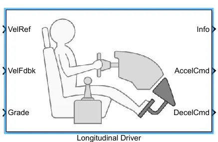
It has following 3 input port which are on the left and 3 output ports on the right side of the block.
VelRef- ( Velocity refrence)- Refrence speed is provided gthrough this input port.
VelFdbk- ( Velocity Feedback)- Feedback of vehicle actual speed is provided through this input port.
Grade- This port provide the gradability or inclination angle for the surface on ehich the vehicle is running.
Info- This is the outport port through which bus signal which consist of block calculation eg acc./deacc. command diffrence between refrence and vehicle speed.
Accel cmd (Acceleration Command):- This outport provide the acc command in the form of 0 and 1 and in this model this command is provided to the controlled voltage source of Acceleration
Decel Cmd (Deacceleration Command)- This outport provide the deacc command in the form of 0 and 1 and in this model this command is provided to the controlled voltage source of Brake.
Block parameter of the Longitudinal driver are as follows:-
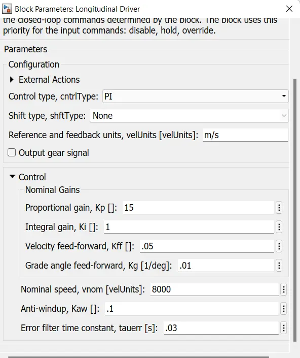
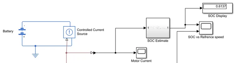
And the last subsystem is of Battery pack
It contain input as Current input coming from Motor controller output through current sensor .
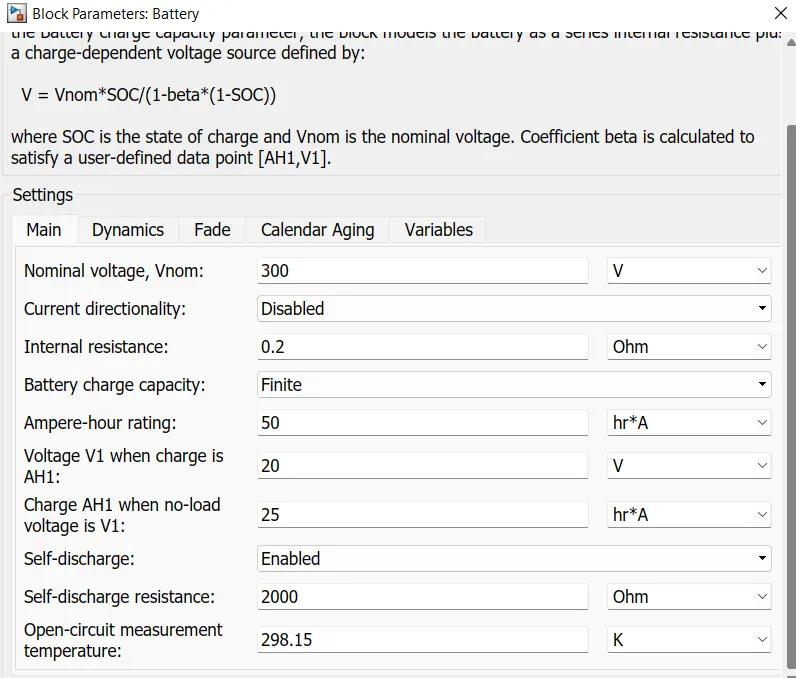
v) Battery pack:- It is the power source of the model so the power could be generated and same power can be transmitted accordingly.
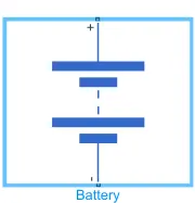
Parameter of Battery pack:-
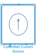
Controlled current source:- It is connected to the positive and negative terminal of the battery and it get the physical signal from the current sensor placed in between the H bridge and Dc motor
I have calculated State of Charge of battery as following:-
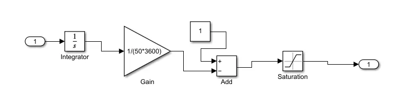
Here current coming from the sensor is applied through an integrator to calculate the current with respect to the time and then its is given to the gain which is having the value of 1/(50*3600) where 50 is the AmpereHour rating of battery and it is subtracted from the constant 1 to tell the remaining charge position of battery.
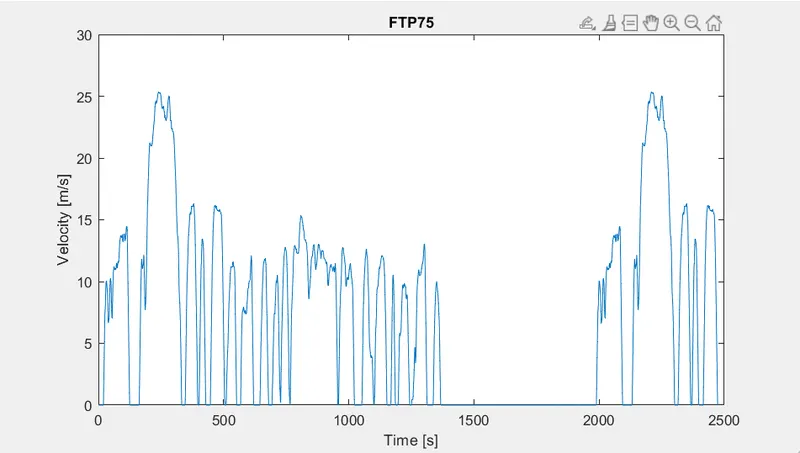
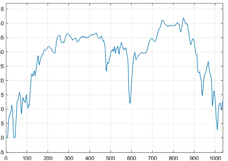
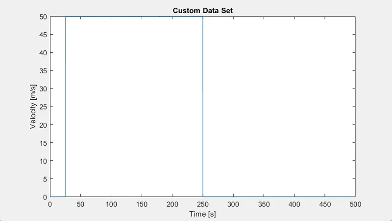
vi)Drive Cycle Source:- It is the data set that contain the velocity and time data for the purpose of modelling the motion of the vehicle. The drive cycle is the plot of velocity vs speed and is mafde according to the real time condition as in resemblance with the typical driving condition. Drive cycle are used by automative comapanies for various vehicle performance test such as mileage, acceleration, speed test, Battery SOC, and vehicle max. speed. There are various drive cycle in this model i have used FTP 75 (2474 s), Artemis Motor 150 and WOT drive cycle to test the vehicle modelling.
Various plot of those drive cycle with time are as follows:-
FTP 75 (2474 sec):-
ii) Artemis Motor 150
iii) WOT Drive Cycle:-
Result :-
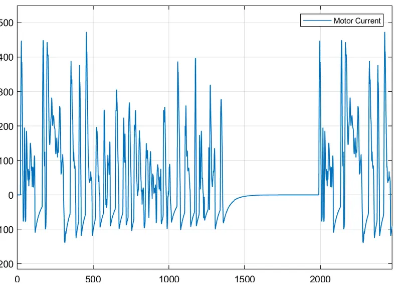
I have used FTP 75 drive cycle to show the results as below:-
Motor Current:-
Battery SOC- From the below plot we can see that the battery SOC behaviour.
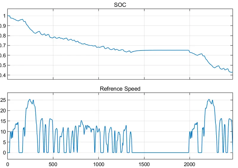
Vehicle Speed vs Refrence speed:-
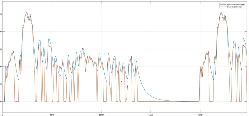
Distance travelled by vehicle:-
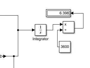
The input is coming from vehicle velocity and it is integrated with time to get the distance and then this input is divided with constant 3600 block to get the distance in Km. The distance travelled is in Km.