Week-7 Challenge: DC Motor Control
Task-1 a) Speed control of a DC motor using BJT H bridge.
Aim:- To study and analyze the working of a BJT H bridge to control speed of DC machine.
Block Used:- Battery Source, IGBT, Diode, Goto and from block, DC machine, Bus selector, Gain, Square, Signum function, Product, Pulse Generator, Constant, Mux, Demux, Step signal, PowerGui.
Working:- In the model Pulse generator is used for generating the pulse signal which is of 500 Hz frequency for 75% duty cycle for a period of 0.002 sec and these signal are given to two Mux and the arrangement are made such that 1 & 4 gets signal of one mux and 2 & 3 gets signal from the pulse generator of another mux and rest other input to the mux are made zero with the help of constant block. These signal are given to switch which operates after 0.5 sec of time from the step signal ( Armature Voltage Control) and the condition of the switch made accordingly. Now the output from the switch is given to the Demux which have four Goto block named as P1, P2, P3 and P4 respectively. These four goto signal will be given to the gate of the IGBT so as to trigger the IGBT ON.
Now a battery source of 240 V is connected across the the four IGBT bridge with DC motor at the centre of the bridge. And 4 diode are connected across each IGBT in parallel so as to provide the path for current to flow when none of the IGBT is ON. The Dc motor Armature is connected in between the bridge and field is given a seprate supply of 300V as the motor is seprately excited one. The measurement are taken out from the point m and Refrence is given through the Torque as an input to the Dc motor. The measurement which were taken from DC motor are given to the Bus Selector and from the selected output like Speed, Armature current and Load Torque is considered. These are fed through the scope to view the behaviour of those parameters. And appropiate conversion were made for angular velocity for converting it into RPM. Now the Angular velocity (in rad/sec) which was recieved as an output from motor is squared as we know that T is directly proportional to sqaure of the angular velocity and multiplied with appropiate gain. along with that a Signum function is also used to tell about the polarity of the velocity. and these two signal are multiplied using a product block. And the output recieved is a fed through a goto block and at DC motor with the help of from block is given as an input to the DC motor.
Result:- The result obtained from the deafult model are shown below
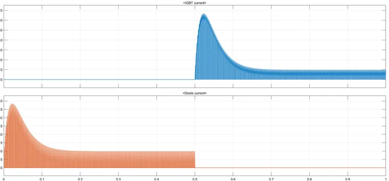
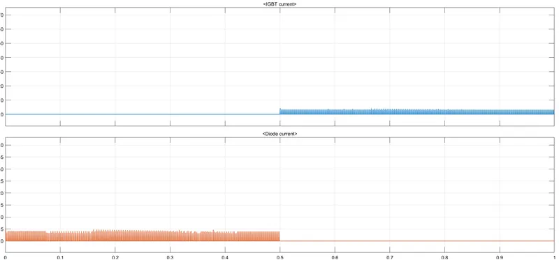
The above graph shows the behaviour of IGBT and Diode Current of Channel 3.
And the below graph shows the behaviour of RPM, Armature current and Load Torque.
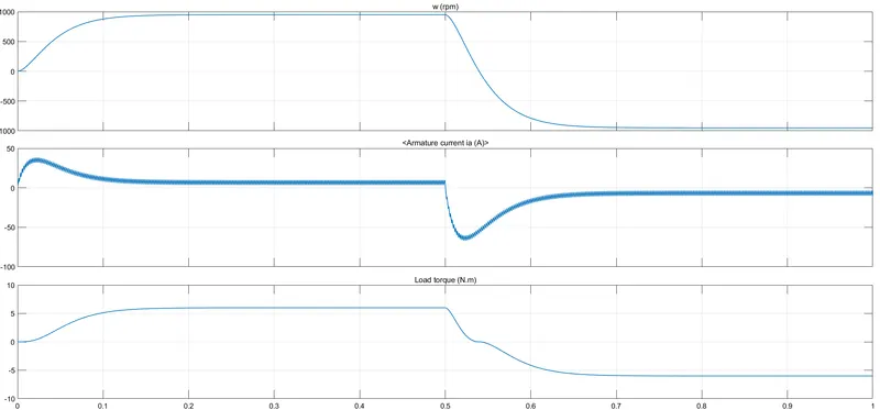
b) The armature current shoot up takes place due to high duty cycle which is 75%
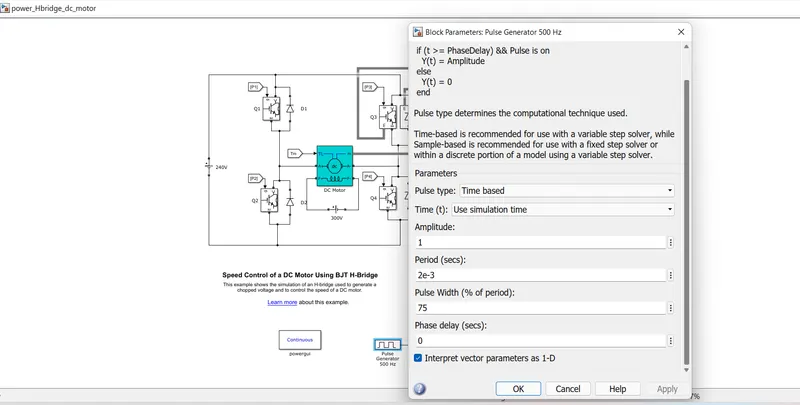
And we can see the reduction in current spike when we change the duty cycle to 50%
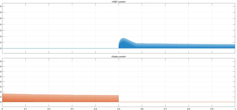
And its gets almost smoothen for the 25% duty cycle.
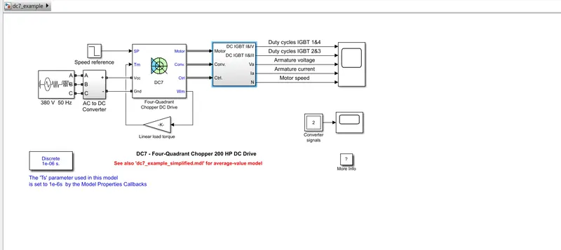
c) Four Quadrant Chopper Dc Drive (DC7) block
The model contain A 3 phase AC source of 380V and 50 Hz Supply which is fed to the AC to DC converter so that it get converted into DC suuply. This DC supply is fed to a Four- Quadrant Chopper Dc Drive
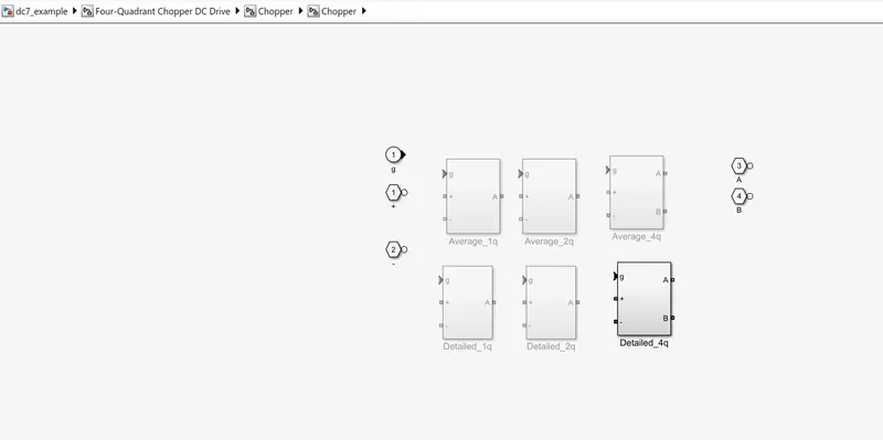
On Right clicking on the Four Quadrant Chopper DC drive block we see the mask option and from there going for look under mask we see the insight of the Chopper circuit as:-
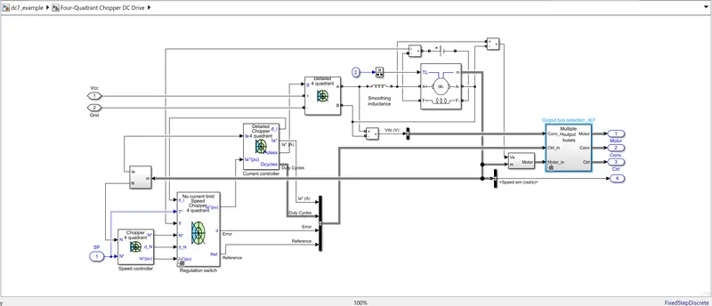
Now visualizing the internal signals of the chopper model:-
Detailed 4 Quadrant block:- Vcc and Ground are the two input along with the g(gate pulse) for the Detailed 4 quadrant block. On opening the look under mask we got to see that out of these six block listed below detailed 4 quadrant is selected. The output of this block are Armature voltage across the Dc motor. The gate pulse which is the input signal of this block comes from Detailed chopper 4 quadrant which is Current Controller.
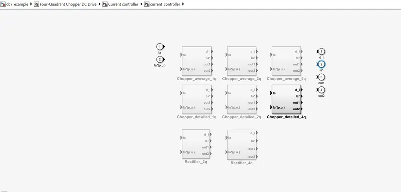
Current Controller:-The input to this block comes as actual current of the motor and Current per unit from the Regulation switch the comaprison between the two current is made here and the output generated from this controller are dI which is given as an input to the Regulation switch which tell about the diference in current, gate pulses are given to the Choper block, Ia* and Duty cycles are given to the output bus selector. Here current controller selectd is of Detailed 4 Q.
Regulation Switch:-
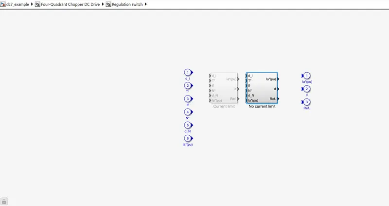
It has following inputs:-
i) dI- coming from current controller
ii)T*- coming from Speed controller to regulate the torque
iii)If- Field current coming from ammeter connected to the field circuit of Dc motor
iv)N*- coming as an input from the speed controller telling about the speed which is to be achieved.
v)dN- Coming from the Speed controller telling about the difference of speed between the actual and refrence speed.
vi)Ia*(pu)- coming from Speed controller telling about the Armature current per phase.
Outputs of Regukation Switch are:-
i)Ia*(pu) - it has been fed to the current controller which is compared with the actual armautre current of motor.
ii)d- error which is given to the Output bus selector
iii)Ref- Reference which is again is fed to the output bus selector.
The No current limit block is selected under the mask.
Speed Controller :-
Inputs:-
N- Motor actual speed
N'- Speed Set point of speed which is to be achieved.
Outputs:-
N*- Speed Set point to be achieved
dN*- Speed difference between the actual and set speed.
Ia*(pu)- which is given as an input to regulation switch.
Now the output from the motor is measured as m and along with the armature voltage constitute a subsystem as follows:-
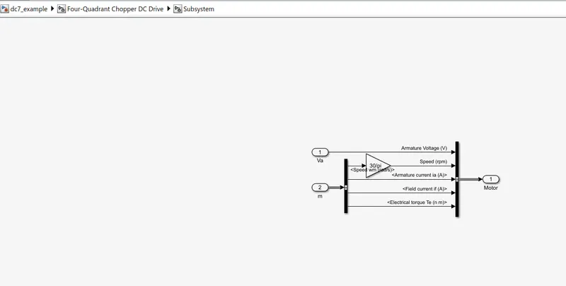
So the Output from the DC -7 block are Motor, Conv and controller which are input of the selector block and from there their behaviour can be seen based upon the parameter value set accordingly. One more output is coming from this DC 7 block and that is angular velocity and when multiplied with suitable gain it is fd as an input to the Dc7 as Motor torque input.
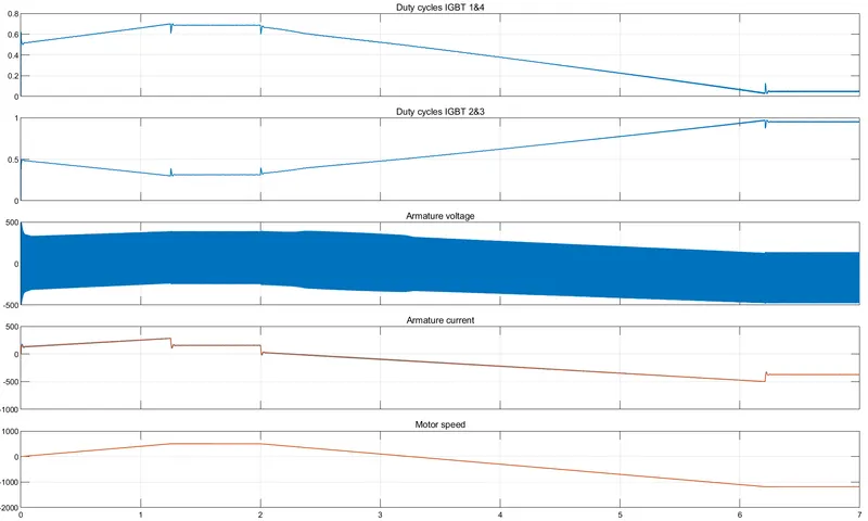
Result:- From the scope are:-
Difference between BJT H bridge and DC7 chopper are listed below:-
i) BJT H bridge operates on only two quadrants while DC7 chopper operates on all the four quadrants.
ii)Stability of volatge and current is higher in Dc7 chopper as compared to BJT h bridge as it uses Step signal for changing the motor direction.
iii)Regenerative braking is not posible in BJT H bridge.
iv) To change direction of motor in DC7 current signals are interrupted while in case of BJT H bridge current polarity has to be reversed.
v) BJT H bridge work on Continous powergui whereas DC & chopper uses Discrete powergui.
Task 2:- To develop a 2 quadrant chopper model using simulink.
Model Url:- https://drive.google.com/drive/folders/14nYX8CBb-IEeleviNy_HO52WzheN-ejn?usp=sharing
Block Used:- Battery Source, IGBT, Diode, Goto and from block, DC machine, Bus selector, Gain, Square, Signum function, Product, Pulse Generator, Constant, Mux, Demux, Step signal, PowerGui.
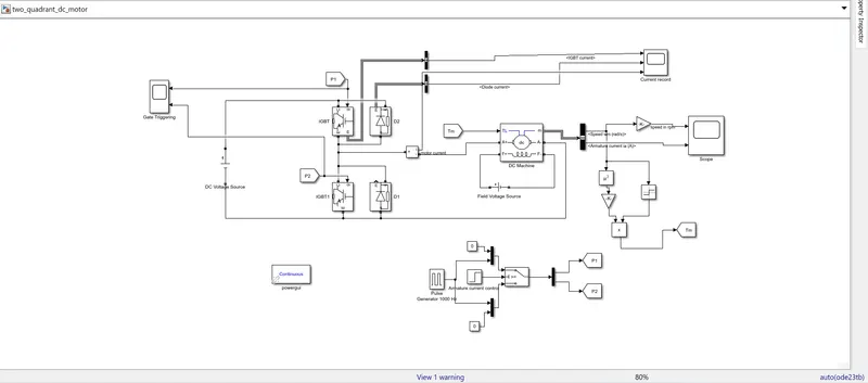
Working:-
In the model Pulse generator is used for generating the pulse signal which is of 1000 Hz frequency for 75% duty cycle for a period of 0.001 sec and these signal are given to two Mux and the arrangement are made such that one mux is given zero value at first input and pulse input at second input and vice versa for other mux. These signal are given to switch which operates after 0.5 sec of time from the step signal ( Armature Current Control) and the condition of the switch made accordingly. Now the output from the switch is given to the Demux which have two Goto block named as P1 & P2 respectively. These two goto signal will be given to the gate of the IGBT so as to trigger the IGBT ON.
Now a battery source of 220 V is connected across the 2 IGBT bridge with DC motor at the centre of the IGBT. And 2 diode are connected across each IGBT in parallel so as to provide the path for current to flow when none of the IGBT is ON. The Dc motor Armature is connected in between the bridge and field is given a seprate supply of 300V as the motor is seprately excited one. The measurement are taken out from the point m and Refrence is given through the Torque as an input to the Dc motor. The measurement which were taken from DC motor are given to the Bus Selector and from the selected output like Speed, Armature current and Load Torque is considered. These are fed through the scope to view the behaviour of those parameters. And appropiate conversion were made for angular velocity for converting it into RPM. Now the Angular velocity (in rad/sec) which was recieved as an output from motor is squared as we know that T is directly proportional to sqaure of the angular velocity and multiplied with appropiate gain. along with that a Signum function is also used to tell about the polarity of the velocity. and these two signal are multiplied using a product block. And the output recieved is a fed through a goto block and at DC motor with the help of from block is given as an input to the DC motor.
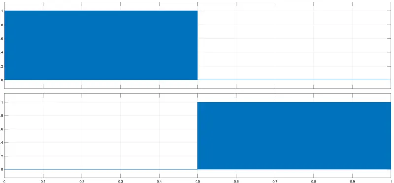
Result:- To monitor that whether the pulses genrated from the pulse generator were able to trigger both the IGBT are not we connected the scope through P1 and P2 block and observe the result as
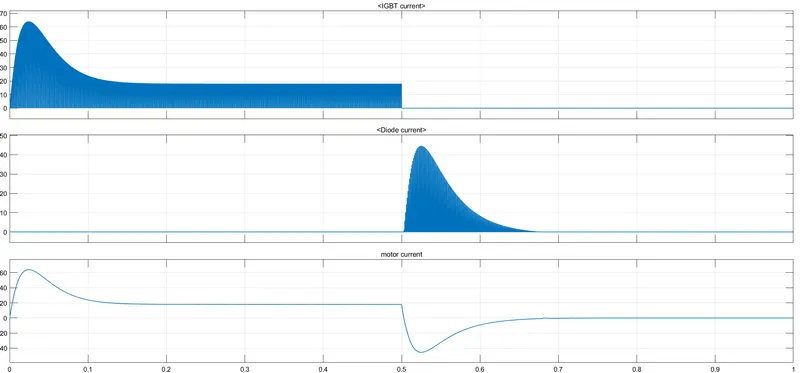
To monitor the effect of IGBT, diode and motor current another scope is used and its result are as follows
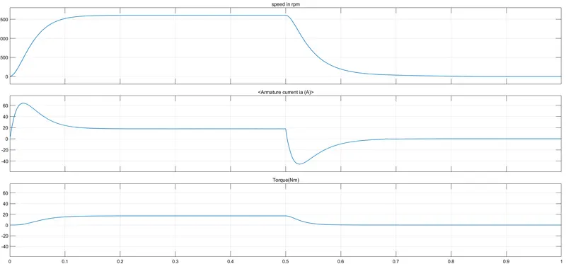
To monitor the Speed, Torque and Armature current of Dc motor we have selected these output from the bus selector and monitor them on scope as
Task-3 Briefing of a Brushless DC Motor:-
Brushless DC motor is a permanent magnet synchronous electric motor which is driven by Direct Current supply. It is based on Electronically Controlled Commutataion system instead of mechanical communation which was used in Brush type Dc motor. BLDC motor employs electrical commutation with permanent magnet rotor and a stator with a sequence of coils. In this motor, permanent magnet rotates and current carrying conductors are fixed.
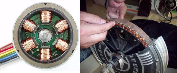
The armature coils placed on the stator are switched electronically by power transistors or SCR's at the correct rotor position in such a way that armature field is in space quadrature with the rotor field poles. Hence the force acting on the rotor causes it to rotate. Hall sensors or rotary encoders are most commonly used to sense the position of the rotor and are positioned around the stator. The rotor position feedback from the sensor helps to determine when to switch the armature current.
Construction of a Brushless DC motor:-
The construction of this motor has many similarities of three phase induction motor as well as conventional DC motor. This motor has stator and rotor parts as like all other motors.
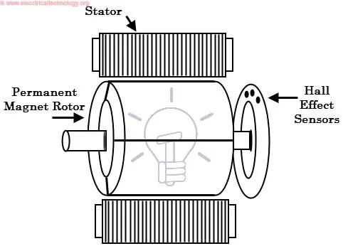
a) Stator
Stator of a BLDC motor made up of stacked steel laminations to carry the windings. These windings are placed in slots which are axially cut along the inner periphery of the stator. These windings can be arranged in either Star or Delta connected. However, most BLDC motors have three phase star connected stator.
Each winding is constructed with numerous interconnected coils, where one or more coils are placed in each slot. In order to form an even number of poles, each of these windings is distributed over the stator periphery.
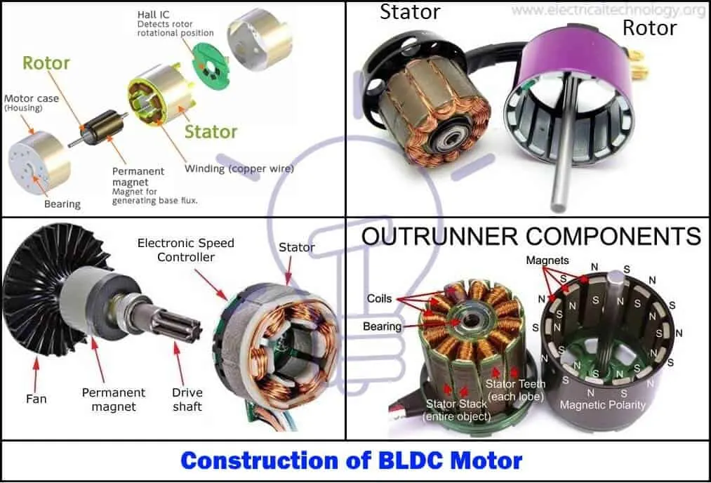
b) Rotor
BLDC motor incorporates a permanent magnet in the rotor. The number of poles in the rotor can vary from 2 to 8 pole pairs with alternate south and north poles depending on the application requirement. In order to achieve maximum torque in the motor, the flux density of the material should be high. A proper magnetic material for the rotor is needed to produce required magnetic field density.
c) Hall Sensor
These are used to determine the position of the rotor. Hall sensor provides the information to synchronize stator armature excitation with rotor position. Since the commutation of BLDC motor is controlled electronically, the stator windings should be energized in sequence in order to rotate the motor. Before energizing a particular stator winding, acknowledgment of rotor position is necessary. So the Hall Effect sensor embedded in stator senses the rotor position.
Most BLDC motors incorporate three Hall sensors which are embedded into the stator. Each sensor generates Low and High signals whenever the rotor poles pass near to it. The exact commutation sequence to the stator winding can be determined based on the combination of these three sensor’s response.
Working of Brushless Dc motor:-
It work on the priciple of Lorentz law that whenever a current carrying conductor placed in a magnetic field it experiences a force. As a consequence of reaction force, the magnet will experience an equal and opposite force. In case BLDC motor, the current carrying conductor is stationary while the permanent magnet moves.
When the stator coils are electrically switched by a supply source, it becomes electromagnet and starts producing the uniform field in the air gap. Though the source of supply is DC, switching makes to generate an AC voltage waveform with trapezoidal shape. Due to the force of interaction between electromagnet stator and permanent magnet rotor, the rotor continues to rotate.
This can be understood from the figure attached below
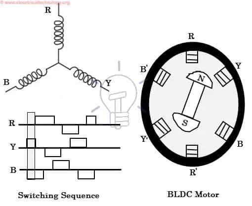
With the switching of windings as High and Low signals, corresponding winding energized as North and South poles. The permanent magnet rotor with North and South poles align with stator poles causing motor to rotate. Motor produces torque because of the development of attraction forces (when North-South or South-North alignment) and repulsion forces (when North-North or South-South alignment). By this way motor moves in a clockwise direction.